KitchenAid KOSE500ESS Dimension Guide
KitchenAid KOSE500ESS Manual
 |
View all KitchenAid KOSE500ESS manuals
Add to My Manuals
Save this manual to your list of manuals |
KitchenAid KOSE500ESS manual content summary:
- KitchenAid KOSE500ESS | Dimension Guide - Page 1
instructions provided for it here. q Oven must be connected to the proper electrical voltage and frequency as specified on the model/serial number rating plate. The model Do not cut the conduit. The length of conduit provided is for serviceability of the oven. q A UL listed or CSA approved conduit - KitchenAid KOSE500ESS | Dimension Guide - Page 2
can be between 26 68.4 cm) and 29 74.8 cm) for single ovens. 27" (68.6 cm) models A. 27" (68.6 cm) min. cabinet width B. 1" (2.5 cm) top of cutout to bottom of right to change materials and specifications without notice. Instructions packed with product. Specifications subject to change without
-
 1
1 -
 2
2
 |
 |
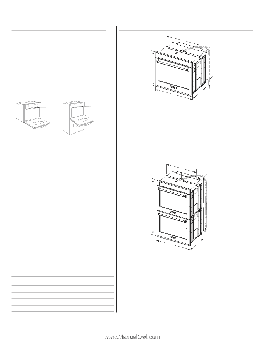
27" (68.6 cm) models
A. 51
³⁄₁₆
" (130.0 cm) max. overall
height
B. 25
⁷⁄₁₆
" (64.6 cm) max.
recessed width
C. 48
¹³⁄₁₆
" (124.0 cm) recessed
height
D. 23
¹⁄₄
" (59.1 cm) max.
recessed depth
E. 27" (68.6 cm) overall width
F. 12" (30.5 cm) from back of
control panel to start of strain
relief
G. 66" (167.6 cm) flexible
conduit length
30" (76.2 cm) models
A. 51
³⁄₁₆
" (130.0 cm) max. overall
height
B. 28½" (72.4 cm) max. recessed
width
C. 48
¹³⁄₁₆
" (124.0 cm) recessed
height
D. 23
¹⁄₄
" (59.1 cm) max. recessed
depth
E. 30" (76.2 cm) overall width
F. 12" (30.5 cm) from back of
control panel to start of strain
relief
G. 66" (167.6 cm) flexible conduit
length
C
B
A
E
D
G
F
27" (68.6 cm) models
A. 28
¾
" (72.8 cm) max. overall
height
B. 25
⁷⁄₁₆
" (64.6 cm) max. recessed
width
C. 26
³⁄₄
" (67.9 cm) recessed
height
D. 23
¹⁄₄
" (59.1 cm) max. recessed
depth
E. 27" (68.6 cm) overall width
F. 12" (30.5 cm) from back of
control panel to start of strain
relief
G. 48" (121.9 cm) flexible conduit
length
30" (76.2 cm) models
A. 28
¾
" (72.8 cm) max. overall
height
B. 28
½
" (72.4 cm) max. recessed
width
C. 26
³⁄₄
" (67.9 cm) recessed
height
D. 23
¹⁄₄
" (59.1 cm) max. recessed
depth
E. 30" (76.2 cm) overall width
F. 12" (30.5 cm) from back of
control panel to start of strain
relief
G. 48" (121.9 cm) flexible conduit
length
B
D
E
A
C
G
F
PRODUCT MODEL SERIES
PRODUCT DIMENSIONS
KODE300E
KODE307E
KODE500E
KODE507E
KODT100E
KODT107E
WOD97EC0E
KOSE500E
KOSE507E
KOST100E
KOST107E
WOS97EC0E
Electrical:
To properly install your oven, you must determine the type of
electrical connection you will be using and follow the instructions
provided for it here.
●
Oven must be connected to the proper electrical voltage and
frequency as specified on the model/serial number rating plate.
The model/serial number rating plate is located under the
control panel on single ovens and under the control panel on
the upper oven cavity on double ovens. See the following
illustrations.
Because Whirlpool Corporation policy includes a continuous commitment to improve
our products, we reserve the right to change materials and specifications without notice.
Dimensions are for planning purposes only. For complete details, see Installation
Instructions packed with product. Specifications subject to change without notice.
Ref. W10725670
12/2/14
27" (68.6 CM) AND 30" (76.2 CM) ELECTRIC SINGLE AND DOUBLE BUILT-IN OVEN
Page 1 of 2
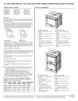
Single Oven
A. Model/serial number plate
Double Oven
A. Model/serial number plate
A
A
●
Models rated from 7.3 to 9.6 kW at 240 volts (5.4 to 7.4 kW at
208 volts) require a separate 40-amp circuit. Models rated at
4.8 kW and below at 240 volts (3.6 kW and below at 208 volts)
require a separate 20-amp circuit.
●
A circuit breaker is recommended.
●
Connect directly to the circuit breaker box (or fused disconnect)
through flexible, armored or nonmetallic sheathed, copper cable
(with grounding wire). See “Make Electrical Connection”
section.
●
Flexible conduit from the oven should be connected directly to
the junction box.
●
Fuse both sides of the line.
●
Do not cut the conduit. The length of conduit provided is for
serviceability of the oven.
●
A UL listed or CSA approved conduit connector must be
provided.
●
If the house has aluminum wiring, follow the procedure below:
1. Connect a section of solid copper wire to the ends of the
flexible conduit leads.
2. Connect the aluminum wiring to the added section of
copper wire using special connectors and/or tools
designed and UL listed for joining copper to aluminum.
Follow the electrical connector manufacturer's recommended
procedure. Aluminum/copper connection must conform with
local codes and industry accepted wiring practices.
For power requirements for models MEW7527, MEW7530,
MEW7627, MEW7630, MEW9537, MEW9627, MEW9530 and
MEW9630, refer to the following table.
Voltage
Single
Single
Double
Double
Double Convect/
Thermal Convect
Thermal Convect
Thermal
240 VAC 4083 W 4141 W 8163 W 8279 W 8221 W
208 VAC 3088 W 3145 W 6172 W 6288 W 6230 W
240 VAC
17.4 A
17.8 A
34.7 A
35.7 A
35.2 A
208 VAC
15.1 A
15.6 A
30.2 A
31.2 A
30.7 A