Konica Minolta magicolor 1690MF Service Manual
Konica Minolta magicolor 1690MF Manual
 |
View all Konica Minolta magicolor 1690MF manuals
Add to My Manuals
Save this manual to your list of manuals |
Konica Minolta magicolor 1690MF manual content summary:
- Konica Minolta magicolor 1690MF | Service Manual - Page 1
SERVICE MANUAL THEORY OF OPERATION magicolor 1680MF magicolor 1690MF 2008.11 Ver. 1.0 - Konica Minolta magicolor 1690MF | Service Manual - Page 2
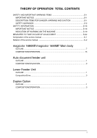
22 Composition of the service manual C-1 Notation of the service manual C-2 magicolor 1680MF/magicolor 1690MF Main body OUTLINE ...7 COMPOSITION/OPERATION 15 Auto document feeder unit OUTLINE ...1 COMPOSITION/OPERATION 3 Lower Feeder Unit OUTLINE ...1 Composition/Drive...3 Duplex Option OUTLINE - Konica Minolta magicolor 1690MF | Service Manual - Page 3
Blank Page ii - Konica Minolta magicolor 1690MF | Service Manual - Page 4
Konica Minolta Business Technologies, INC. (hereafter called the KMBT) strongly recommends that all servicing be performed only by KMBTtrained service technicians. Changes may have been made to this product to improve its performance after this Service Manual wound, medium trouble and property damage - Konica Minolta magicolor 1690MF | Service Manual - Page 5
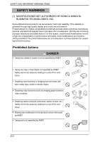
KONICA MINOLTA BUSINESS TECHNOLOGIES, INC. Konica Minolta brand products are renowned for their high reliability. This reliability is achieved through high-quality design and a solid service . • Making any modification to the product unless instructed by KMBT • Using parts not specified by KMBT S-2 - Konica Minolta magicolor 1690MF | Service Manual - Page 6
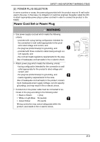
or electric shock. • Conductors in the power cable must be connected to ter- minals of the plug according to the following order: • Black or Brown: L (line) • White or Light Blue: N (neutral) • Green/Yellow: PE (earth) Wrong connection may cancel safeguards within the product, and results - Konica Minolta magicolor 1690MF | Service Manual - Page 7
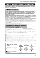
AND IMPORTANT WARNING ITEMS [3] CHECKPOINTS WHEN PERFORMING ON-SITE SERVICE Konica Minolta brand products are extensively tested before shipping, to ensure power cord is plugged in the wall outlet securely. Contact problems may lead to increased resistance, overheating, and the risk of fire. S-4 - Konica Minolta magicolor 1690MF | Service Manual - Page 8
cord (inlet type) is not connected to the product securely, a contact problem may lead to increased resistance, overheating, and risk of fire. • Check with a new power cord or cord set (with plug and connector on each end) specified by KMBT. Using the damaged power cord may result in fire or - Konica Minolta magicolor 1690MF | Service Manual - Page 9
Power Plug and Cord WARNING • Check whether dust is collected around the power plug and wall outlet. Using the power plug and wall outlet without removing dust may result in fire. • Do not insert the power plug into the wall outlet with a wet hand. The risk of electric shock exists. • When - Konica Minolta magicolor 1690MF | Service Manual - Page 10
SAFETY AND IMPORTANT WARNING ITEMS 2. Installation Requirements Prohibited Installation Places WARNING • Do not place the product near flammable materials or volatile materials that may catch fire. A risk of fire exists. • Do not place the product in a place exposed to water such as rain. A risk of - Konica Minolta magicolor 1690MF | Service Manual - Page 11
• Before conducting an inspection, read all relevant documentation (service manual, technical notices, etc.) and proceed with the inspection . When the power plug is inserted in the wall outlet, some units are still powered even if the POWER switch is turned OFF. Arisk of electric shock exists. • - Konica Minolta magicolor 1690MF | Service Manual - Page 12
can leak, leading to a risk of electric shock or fire. • Carefully remove all toner remnants and dust from electrical parts and electrode units such as a charging corona unit. Current can leak, leading to a risk of product trouble or fire. • Check high-voltage cables and sheaths for any damage - Konica Minolta magicolor 1690MF | Service Manual - Page 13
unit shifted from the specified mounting position. The laser light can enter your eye, leading to a risk of loss of eyesight. • When replacing a lithium battery, replace it with a new lithium battery specified in the Parts Guide Manual (e.g., for clearing paper jam). • Make sure the were removed for - Konica Minolta magicolor 1690MF | Service Manual - Page 14
with plenty of water immediately. When symptoms are noticeable, consult a physician. • Never throw the used cartridge and toner into fire. You may be burned due to dust explosion. Handling of Service Materials CAUTION • Unplug the power cord from the wall outlet. Isopropyl alcohol and acetone are - Konica Minolta magicolor 1690MF | Service Manual - Page 15
me type ou d'un type équivalent recom- mandé par le constructeur. Mettre au rebut les batteries usagées conformément aux instructions du fabricant. • Denmark ADVARSEL! Lithiumbatteri - Eksplosionsfare ved fejlagtig håndtering. Udskiftning må kun ske med batteri af samme fabrikat og type. Lev - Konica Minolta magicolor 1690MF | Service Manual - Page 16
of danger from a laser, provided the machine is serviced according to the instruction in this manual. 4.1 Internal Laser Radiation semiconductor laser Maximum power of the laser diode Maximum average radiation power (*) Wavelength *at laser aperture of the Print Head Unit 20 mW 13.3 µW 775 - Konica Minolta magicolor 1690MF | Service Manual - Page 17
U.S. Department of Health and Human Services (DHHS). This means that the device does not produce hazardous laser radiation. • The label shown on page S-16 indicates compliance with the CDRH regulations and must be attached to laser products marketed in the United States. . CAUTION • Use of controls - Konica Minolta magicolor 1690MF | Service Manual - Page 18
• Laitteen käyttäminen muulla kuin tässä käyttöohjeessa mainitulla tavalla saat- taa altistaa käyttäjän turvallisuusluokan 1 ylittävälle näkymättömälle lasersäteilylle. puolijohdelaser Laserdiodin suurin teho aallonpituus 20 mW 775 - 800 nm VARNING! • Om apparaten används på annat sätt än i denna - Konica Minolta magicolor 1690MF | Service Manual - Page 19
SAFETY AND IMPORTANT WARNING ITEMS 4.2 Laser Safety Label • A laser safety label is attached to the inside of the machine as shown below. M A0HFP0C500DA S-16 - Konica Minolta magicolor 1690MF | Service Manual - Page 20
lens conforming to the above specifications. • When a disassembly job needs to be performed in the laser beam path, such as when working around the printerhead and PC Drum, be sure first to turn the printer OFF. • If the job requires that the printer be left ON, take off your watch and ring and wear - Konica Minolta magicolor 1690MF | Service Manual - Page 21
manufactured since August 1, 1976. Compliance is mandatory for products marketed in the United States. This copier is certified as a "Class 1" laser product under the U.S. Department of Health and Human Services (DHHS) Radiation Performance Standard according to the Radiation Control for Health and - Konica Minolta magicolor 1690MF | Service Manual - Page 22
these areas for maintenance, repair, or adjustment, special care should be taken to avoid burns and electric shock. CAUTION • The area around the Fuser Unit is extremely hot. Touching any part other than those indicated may result in burns. M High voltage • This area generates high voltage. Be - Konica Minolta magicolor 1690MF | Service Manual - Page 23
SAFETY INFORMATION High voltage • This area generates high voltage. Be careful not to touch here when the power is turned ON to avoid getting an electric shock. A0HFP0C504DA S-20 - Konica Minolta magicolor 1690MF | Service Manual - Page 24
SAFETY INFORMATION WARNING • Do not burn used Imaging Cartridge. Toner expelled from the fire is dangerous. WARNING • Do not burn used Toner Cartridges. Toner expelled from the fire is dangerous. A0HFP0505DA CAUTION: • You may be burned or injured if you touch any area that you are advised by any - Konica Minolta magicolor 1690MF | Service Manual - Page 25
must be notified. 3. To determine the cause of the accident, conditions and materials must be recorded through direct on-site checks, in accordance with instructions issued by KMBT. 4. For reports and measures concerning serious accidents, follow the regulations specified by every distributor. S-22 - Konica Minolta magicolor 1690MF | Service Manual - Page 26
specifications Explanation of service schedule, maintenance steps, service tools, removal/reinstallation methods of major parts, and firmware version up method etc. Explanation of utility mode, service mode, and mechanical adjustment etc. Explanation of lists of jam codes and error codes, and their - Konica Minolta magicolor 1690MF | Service Manual - Page 27
of the service manual A. Product name In this manual, each of the products is described as follows: (1) magicolor 1680MF/magicolor 1690MF Main body (2) Microsoft Windows NT 4.0: Windows NT 4.0 or Windows NT Microsoft Windows 2000: Windows 2000 Microsoft Windows XP: Windows XP Microsoft - Konica Minolta magicolor 1690MF | Service Manual - Page 28
SERVICE MANUAL THEORY OF OPERATION magicolor 1680MF magicolor 1690MF Main body 2008.11 Ver. 1.0 - Konica Minolta magicolor 1690MF | Service Manual - Page 29
for improvement of their performance. Therefore, the descriptions given in this service manual may not coincide with the actual machine. When any change has been made to the descriptions in the service manual, a revised version will be issued with a revision mark added as required. Revision mark - Konica Minolta magicolor 1690MF | Service Manual - Page 30
...19 8.2.1 Outline...19 8.2.2 Laser exposure process 19 8.2.3 Laser emission area 20 8.2.4 Image stabilization control item 20 9. Imageing cartridge section 21 9.1 Composition...21 9.2 Drive ...22 9.3 Operation ...22 9.3.1 Imaging cartridge (IC) life control 22 10. Photo conductor section 23 - Konica Minolta magicolor 1690MF | Service Manual - Page 31
.3.5 Developing system 35 12.3.6 Toner cartridge (TC) life control 35 13. 1st transfer section 36 13.1 Composition ...36 13.2 Drive ...37 13.3 Operation...38 13.3.1 1st transfer output control 38 13.3.2 Transfer belt cleaning mechanism 38 13.3.3 Cleaning blade pressure/retraction mechanism 39 - Konica Minolta magicolor 1690MF | Service Manual - Page 32
magicolor 1680MF magicolor 1690MF OUTLINE COMPOSITION/ OPERATION Theory of Operation Ver. 1.0 Nov. 2008 15.3 Operation ...51 15.3.1 Toner collecting mechanism 51 15.3.2 Waste toner detection control 64 19. Image stabilization control 65 19.1 of toner sticking 66 19.2.5 Laser intensity - Konica Minolta magicolor 1690MF | Service Manual - Page 33
magicolor 1680MF magicolor 1690MF OUTLINE COMPOSITION/ OPERATION Theory of Operation Ver. 1.0 Nov. 2008 20.1 Composition ...68 20.2 Operation...68 20.2.1 Function ...68 20.2.2 Control conditions 69 iv - Konica Minolta magicolor 1690MF | Service Manual - Page 34
. 2008 OUTLINE 1. System configuration A. magicolor 1680MF [1] 1. System configuration [2] [1] magicolor 1680MF B. magicolor 1690MF [1] M [2] Dust cover (Option) A0HFT2C515AA [2] [2] [1] magicolor 1690MF [2] Lower Feeder Unit (Option) [4] [3] A0HFT1C500AA [3] Duplex Option Attachment (Option - Konica Minolta magicolor 1690MF | Service Manual - Page 35
full-color laser beam printer Semiconductor laser and electrostatic image transfer to plain paper 2 laser diodes and polygon mirror OPC (organic photo conductor) Blade cleaning system 1200 x 600 dpi, 600 x 600 dpi magicolor 1680MF One-way system (Tray 1: 200 sheets) magicolor 1690MF One - Konica Minolta magicolor 1690MF | Service Manual - Page 36
:200 sheets Thick stock, postcards, labels stock, and glossy stock :50 sheets Envelopes :10 sheets Lower Feeder Unit: Only plain paper and recycled paper weighing 60 to 90 g/m2 (16 to 24 lb) can be loaded. Duplex Option: Only plain paper and recycled paper weighing 60 to 90 g/m2 (16 to 24 - Konica Minolta magicolor 1690MF | Service Manual - Page 37
(including the consumables) magicolor 1690MF 21.0 kg (including the consumables) During standby magicolor 1680MF 38 dB (A) magicolor 1690MF During printing magicolor 1680MF 50 dB (A): Color magicolor 1690MF 49 dB (A): monochrome E. Operating environment Temperature Humidity 10 to 35 °C / 50 - Konica Minolta magicolor 1690MF | Service Manual - Page 38
Pack 2 or later), Windows XP Professional x64 Edition, Windows Server 2003, Windows Server 2003 x64 Edition, Windows 2000 (Service Pack 4 or later) . Mac OS X (10.2.8 or later; We recommend installing the latest patch) NOTE • These specifications are subject to change without notice. OUTLINE 11 - Konica Minolta magicolor 1690MF | Service Manual - Page 39
cross section 3. Center cross section Theory of Operation Ver. 1.0 Nov. 2008 Scanner section Imaging cartridge section Auto document feeder section* Toner cartridge section Write section Media feed section *: Only for the magicolor 1690MF Fusing section 2nd transfer section A0HFT2C518AA 12 - Konica Minolta magicolor 1690MF | Service Manual - Page 40
magicolor 1600W magicolor 1650EN Theory of Operation Ver. 1.0 Nov. 2008 4. Media path 4. Media path A0HFT2C516AA OUTLINE A0HFT2C517AA 13 - Konica Minolta magicolor 1690MF | Service Manual - Page 41
4. Media path Theory of Operation Ver. 1.0 Nov. 2008 magicolor 1600W magicolor 1650EN OUTLINE Blank Page 14 - Konica Minolta magicolor 1690MF | Service Manual - Page 42
/OPERATION 5. Overall composition 5.1 Control block diagram 5. Overall composition Scanner Control panel FAX* MFP board (MFPB) Image processing Write unit (PH ) Control system line *: Only for the magicolor 1690MF TC/Y TC/M TC/C TC/K Print control board (PRCB) CPU Paper pi ck-up/ transport - Konica Minolta magicolor 1690MF | Service Manual - Page 43
2008 magicolor 1680MF magicolor 1690MF COMPOSITION/ OPERATION [9] Transfer belt cleaning [2] Photo conductor [6] 1st image transfer [8] Media separation [7] 2nd image transfer [5] Developing [10] PC drum cleaning [3] Photo conductor charging [1] Printer image processing [4] Laser exposure - Konica Minolta magicolor 1690MF | Service Manual - Page 44
motor 2nd transfer output 2nd image transfer pressure/ retraction solenoid Cleaning blade pressure/ retraction solenoid 1st transfer output Y setting voltage M setting voltage C setting voltage K setting voltage COMPOSITION/ OPERATION magicolor 1680MF magicolor 1690MF Theory of Operation Ver - Konica Minolta magicolor 1690MF | Service Manual - Page 45
magicolor 1680MF magicolor 1690MF 6. Interface section 6. Interface section 6.1 Composition 6.1.1 magicolor 1680MF Theory of Operation Ver. 1.0 Nov. 2008 USB port (USB 2.0) Type USB port Application For PC to printer connection A0HFT2C502AA COMPOSITION/ OPERATION 18 - Konica Minolta magicolor 1690MF | Service Manual - Page 46
magicolor 1680MF magicolor 1690MF Theory of Operation Ver. 1.0 Nov. 2008 6.1.2 magicolor 1690MF 6. Interface section TEL (telephone) jack LINE ( line) jack For fax machine connection USB port For PC to printer connection 10Base-T/100Base-TX (IEEE802.3) Ethernet Interface port For network USB - Konica Minolta magicolor 1690MF | Service Manual - Page 47
magicolor 1680MF magicolor 1690MF 7. Scanner section 7. Scanner section 7.1 Composition Theory of Operation Ver. 1.0 Nov. 2008 A0HFT2C502AA Scanner motor (M101) A0HFT2C501AA COMPOSITION/ OPERATION Exposure unit A0HFT2C512AA 20 - Konica Minolta magicolor 1690MF | Service Manual - Page 48
magicolor 1680MF magicolor 1690MF Theory of Operation Ver. 1.0 Nov. 2008 7.2 Drive 7. Scanner section A0HFT2C505AA COMPOSITION/ OPERATION 21 - Konica Minolta magicolor 1690MF | Service Manual - Page 49
magicolor 1680MF magicolor 1690MF 7. Scanner section Theory of Operation Ver. 1.0 Nov. 2008 7.3 Operation 7.3.1 When the Start key is pressed A. Original reading mode (1) Original cover mode 1. Press the start key, and the LED lights ON. 2. The exposure units moves from the home position (stand- - Konica Minolta magicolor 1690MF | Service Manual - Page 50
magicolor 1680MF magicolor 1690MF COMPOSITION/ OPERATION Theory of Operation Ver. 1.0 Nov. 2008 7. Scanner section (2) DF mode 1. Press the start key, and the LED lights ON. 2. The exposure units be the boarder between the white and black of the shading sheet is searched of image element of - Konica Minolta magicolor 1690MF | Service Manual - Page 51
magicolor 1680MF magicolor 1690MF 8. Write section (PH section) 8. Write section (PH section) 8.1 Composition Theory of Operation Ver. 1.0 Nov. 2008 SOS mirror G2 lens G1 Lens Polygon mirror A034T2C574AA Return mirror SOS sensor Semiconductor laser A034T2C504AA COMPOSITION/ OPERATION 24 - Konica Minolta magicolor 1690MF | Service Manual - Page 52
magicolor 1680MF magicolor 1690MF Theory of Operation Ver. 1.0 Nov. 2008 8. Write section (PH section) 8.2 Operation 8.2.1 Outline • The surface of the photo conductor is irradiated with a laser light and an electrostatic latent image is thereby formed. • The polygon mirror has four faces. The - Konica Minolta magicolor 1690MF | Service Manual - Page 53
magicolor 1680MF magicolor 1690MF 8. Write section (PH section) Theory of Operation Ver. 1.0 Nov. 2008 8.2.3 Laser emission area A. is, however, the void image area. B. Sub scan direction (FD) • The print start position in the FD direction is determined by the Image write start signal (/ TOD) - Konica Minolta magicolor 1690MF | Service Manual - Page 54
magicolor 1680MF magicolor 1690MF Theory of Operation Ver. 1.0 Nov. 2008 9. Imageing cartridge section 9.1 Composition 9. Imageing cartridge section Photo conductor Charge corona Driven roller2 A034T2C554AA Transfer belt 1st transfer roller Driven roller1 A034T2C506AA COMPOSITION/ OPERATION - Konica Minolta magicolor 1690MF | Service Manual - Page 55
section 9.2 Drive Theory of Operation Ver. 1.0 Nov. 2008 magicolor 1680MF magicolor 1690MF COMPOSITION/ OPERATION A034T2C508AA 9.3 Operation 9.3.1 Imaging cartridge (IC) life control A. New DC detection • The machine attempts to perform a new IC detection sequence when the power switch is - Konica Minolta magicolor 1690MF | Service Manual - Page 56
magicolor 1680MF magicolor 1690MF Theory of Operation Ver. 1.0 Nov. 2008 10. Photo conductor section 10.1 Composition Photo conductor 10. Photo conductor section Charge generating layer Charge transport layer Aluminum base 10.2 Drive A034T2C555AA 4139to2057e1 Photo conductor Transport - Konica Minolta magicolor 1690MF | Service Manual - Page 57
the Main motor (M1). 10.3.2 Photo conductor cleaning mechanism • The cleaning blade is pressed up against the surface of the photo conductor, scraping residual toner off the surface. • The toner scraped off the surface of the photo conductor is collected in the drum cartridge. Transfer belt Photo - Konica Minolta magicolor 1690MF | Service Manual - Page 58
Theory of Operation Ver. 1.0 Nov. 2008 11. Charge corona section 11.1 Composition 11. Charge corona section magicolor 1680MF magicolor 1690MF COMPOSITION/ OPERATION A034T2C570AA A034T2C569AA Photo conductor Charge corona A034T2C510AA 11.2 Operation 11.2.1 Charge corona control A. Charging grid - Konica Minolta magicolor 1690MF | Service Manual - Page 59
magicolor 1680MF magicolor 1690MF 12. Developing section 12. Developing section 12.1 Composition Theory of Operation Ver. 1.0 Nov. 2008 Hopper section Supply section Developing roller A034T2C571AA Y Developing roller Y K Supply roller - Konica Minolta magicolor 1690MF | Service Manual - Page 60
magicolor 1680MF magicolor 1690MF Theory of Operation Ver. 1.0 Nov. 2008 12.2 Drive Imaging cartridge 12. Developing section COMPOSITION/ OPERATION Transport motor Rack motor A034T2C511AA 12.3 Operation 12.3.1 Toner flow • Toner stored in the hopper is conveyed into the toner supply portion - Konica Minolta magicolor 1690MF | Service Manual - Page 61
magicolor 1690MF 12. Developing section Theory of Operation Ver. 1.0 Nov. 2008 12.3.2 Toner Cartridge Rack • The toner cartridge rack is mounted with four toner cartridges. The rack employs a rotary system. • Development of the image of each color of toner is performed by rotating the toner - Konica Minolta magicolor 1690MF | Service Manual - Page 62
magicolor 1680MF magicolor 1690MF COMPOSITION/ OPERATION Theory of Operation Ver. 1.0 Nov. 2008 12. Developing section B. Toner cartridge rack stop position • The toner cartridge rack must be brought to a stop so that the toner cartridge of each color of toner is located at its correct position. - Konica Minolta magicolor 1690MF | Service Manual - Page 63
magicolor 1680MF magicolor 1690MF 12. Developing section Theory of Operation Ver. 1.0 Nov. 2008 (3) Cartridge replacement position • The cartridge replacement position is where the toner cartridge rack is rotated 90° from the developing position. For developing of C 90° C M K Y K C Y M - Konica Minolta magicolor 1690MF | Service Manual - Page 64
magicolor 1680MF magicolor 1690MF Theory of Operation Ver. 1.0 Nov. 2008 12. Developing section D. Color printing process (1) Operation sequence 1. The toner cartridge rack is stationary at the standby position. 2. When a print request is received from the controller, the toner cartridge rack is - Konica Minolta magicolor 1690MF | Service Manual - Page 65
magicolor 1680MF magicolor 1690MF 12. Developing section Theory of Operation Ver. 1.0 Nov. 2008 E. Toner cartridge rack stop position detection • The toner cartridge rack stop position for each color of toner is detected by the Rack motor (M2) and the Rack positioning sensor (PS5). • The toner - Konica Minolta magicolor 1690MF | Service Manual - Page 66
position • When a request is made for replacing the toner cartridge of a specific color of toner (by means of an input from the control panel, upon a toner empty condition, or through an input made via the printer driver), the toner cartridge rack is rotated 70° from the developing position through - Konica Minolta magicolor 1690MF | Service Manual - Page 67
magicolor 1680MF magicolor 1690MF 12. Developing section Theory of Operation Ver. 1.0 Nov. 2008 12.3.3 Developing Roller drive • The developing roller is driven by the Developing motor (M3) and Intermediate gear. • When the toner cartridge rack is stationery at the developing position, the - Konica Minolta magicolor 1690MF | Service Manual - Page 68
magicolor 1680MF magicolor 1690MF COMPOSITION/ OPERATION Theory of image). This prevents a foggy image from occurring and the photo conductor from being worn. Developing roller Photo conductor 4139to2063e2 12.3.6 Toner cartridge (TC) life control A. Toner cartridge detection and new cartridge - Konica Minolta magicolor 1690MF | Service Manual - Page 69
magicolor 1680MF magicolor 1690MF 13. 1st transfer section 13. 1st transfer section 13.1 Composition Theory of Operation Ver. 1.0 Nov. 2008 IDC sensor (IDC) A034T2C570AA Driven roller 2 1st transfer roller A034T2C527AA Transfer belt Toner collecting screw Cleaning blade Belt positioning - Konica Minolta magicolor 1690MF | Service Manual - Page 70
magicolor 1680MF magicolor 1690MF Theory of Operation Ver. 1.0 Nov. 2008 13.2 Drive 13. 1st transfer section A034T2C508AA COMPOSITION/ OPERATION 43 - Konica Minolta magicolor 1690MF | Service Manual - Page 71
1680MF magicolor 1690MF 13. 1st transfer section Theory of Operation Ver. 1.0 Nov. 2008 13.3 Operation 13.3.1 1st transfer output control • The 1st image transfer roller is not equipped with a pressure/retraction mechanism and presses the transfer belt up against the photo conductor drum. • The - Konica Minolta magicolor 1690MF | Service Manual - Page 72
magicolor 1680MF magicolor 1690MF Theory of Operation Ver. 1.0 Nov. 2008 13. 1st transfer section 13.3.3 Cleaning blade pressure/retraction mechanism • In color printing, an image is formed on the transfer belt for each color of toner. The cleaning blade is therefore provided with a pressure/ - Konica Minolta magicolor 1690MF | Service Manual - Page 73
magicolor 1680MF magicolor 1690MF 13. 1st transfer section B. Operation timing Theory of Operation Ver. 1.0 Nov. 2008 Cleaning blade pressure/ 㪦㪥 retraction solenoid 㪦㪝㪝 Point of contact with the transfer belt Cleaning blade pressure/ retraction condition Retraction stop During pressure - Konica Minolta magicolor 1690MF | Service Manual - Page 74
magicolor 1680MF magicolor 1690MF Theory of Operation Ver. 1.0 Nov. 2008 13. 1st transfer section D. Pressure sequence 1. When the Cleaning blade pressure/retraction solenoid (SD5) is energized in the condition, in which the cleaning blade is retracted from the transfer belt, the pressure cam - Konica Minolta magicolor 1690MF | Service Manual - Page 75
magicolor 1690MF 13. 1st transfer section Theory of Operation Ver. 1.0 Nov. 2008 13.3.4 Belt Positioning Sensor • When development takes place in this machine, the image of each color of toner is formed on the surface of the transfer belt. The leading edge of the image of each color of toner - Konica Minolta magicolor 1690MF | Service Manual - Page 76
magicolor 1680MF magicolor 1690MF COMPOSITION/ image stabilization control. • The 2nd transfer ATVC operation is performed when, for example, environmental conditions change current for each color of toner output from the High voltage unit (HV) is fed back to the High voltage unit via the 1st - Konica Minolta magicolor 1690MF | Service Manual - Page 77
magicolor 1680MF magicolor 1690MF 13. 1st transfer section Theory of Operation Ver. 1.0 Nov. 2008 13.3.6 Image stabilization control item • IDC sensor LED intensity control • Transfer belt surface correction control • Control of the maximum amount of toner sticking • Laser intensity adjustment - Konica Minolta magicolor 1690MF | Service Manual - Page 78
magicolor 1690MF Theory of Operation Ver. 1.0 Nov. 2008 14. 2nd transfer section/ media separation 14. 2nd transfer section/ media separation 14.1 Composition 2nd transfer roller 2nd transfer roller A034T2C557AA Pressure/ Retraction slider A034T2C533AA COMPOSITION/ OPERATION 2nd image - Konica Minolta magicolor 1690MF | Service Manual - Page 79
magicolor 1680MF magicolor 1690MF 14. 2nd transfer section/ media separation 14.2 Drive Theory of Operation Ver. 1.0 Nov. 2008 2nd transfer roller Transport motor (M1) A034T2C534AA COMPOSITION/ OPERATION 52 - Konica Minolta magicolor 1690MF | Service Manual - Page 80
magicolor 1680MF magicolor 1690MF Theory of Operation Ver. 1.0 Nov. 2008 14. 2nd transfer section/ media separation 14.3 Operation 14.3.1 2nd transfer roller pressure/retraction control • In color printing, the toner image of each color of toner is transferred to the transfer belt (thus a total - Konica Minolta magicolor 1690MF | Service Manual - Page 81
magicolor 1680MF magicolor 1690MF 14. 2nd transfer section/ media separation Theory of Operation Ver. 1.0 Nov. 2008 (1) Retraction sequence 1. When the 2nd image belt, thus cleaning the 2nd transfer roller. • The toner transferred back to the transfer belt is collected by the cleaning blade. 2nd - Konica Minolta magicolor 1690MF | Service Manual - Page 82
magicolor 1680MF magicolor 1690MF Theory of Operation Ver. 1.0 Nov. 2008 14. 2nd transfer section/ media separation 14.3.3 Neutralization and separation of media • To neutralize the media that has undergone the 2nd transfer process, a Charge neutralizing cloth is provided for the guide plate - Konica Minolta magicolor 1690MF | Service Manual - Page 83
1680MF magicolor 1690MF 15. Toner collecting section 15. Toner collecting section 15.1 Composition Toner collecting screw 1 Theory of Operation Ver. 1.0 Nov. 2008 Toner collecting screw 2 COMPOSITION/ OPERATION 15.2 Drive Waste toner near full sensor A034T2C537AA Toner collecting screw 1 Toner - Konica Minolta magicolor 1690MF | Service Manual - Page 84
magicolor 1680MF magicolor 1690MF Theory of Operation Ver. 1.0 Nov. 2008 15. Toner collecting section 15.3 Operation 15.3.1 Toner collecting mechanism • Waste toner scraped off by the cleaning blade of the transfer belt and that scraped off by the cleaning blade of the photo conductor are - Konica Minolta magicolor 1690MF | Service Manual - Page 85
magicolor 1680MF magicolor 1690MF 15. Toner collecting section Theory of Operation Ver. 1.0 Nov. 2008 15.3.2 Waste toner near full detection system • Waste toner near full and waste toner full conditions are detected through the control performed using the Waste toner near full sensor, toner - Konica Minolta magicolor 1690MF | Service Manual - Page 86
magicolor 1680MF magicolor 1690MF Theory of Operation Ver. 1.0 Nov. 2008 16. Media feed section 16.1 Composition Media feed roller 16. Media feed section A034T2C558AA Tray1 media feed solenoid (SD1) A034T2C559AA Media feed roller A0HFT2C508AA COMPOSITION/ OPERATION 59 - Konica Minolta magicolor 1690MF | Service Manual - Page 87
magicolor 1680MF magicolor 1690MF 16. Media feed section 16.2 Drive Transport motor (M1) Tray1 media feed solenoid (SD1) Theory of Operation Ver. 1.0 Nov. 2008 Media feed roller A034T2C542AA COMPOSITION/ OPERATION 60 - Konica Minolta magicolor 1690MF | Service Manual - Page 88
magicolor 1680MF magicolor 1690MF Theory of Operation Ver. 1.0 Nov. 2008 16. Media feed section 16.3 Operation 16.3.1 Up/down control A. Up/down operation • When the Tray1 Paper pick-up - Konica Minolta magicolor 1690MF | Service Manual - Page 89
magicolor 1680MF magicolor 1690MF 16. Media feed section Theory of Operation Ver. 1.0 Nov. 2008 16.3.2 Paper feed control A. Pick-up/separation control • When the Tray 1 media feed solenoid (SD1) - Konica Minolta magicolor 1690MF | Service Manual - Page 90
magicolor 1680MF magicolor 1690MF Theory of Operation Ver. 1.0 Nov. 2008 16. Media feed section 16.3.5 Media feed retry function • To reduce the number of media misfeeds detected due to failure to take up and feed in media properly during color printing, another media feed sequence is carried out - Konica Minolta magicolor 1690MF | Service Manual - Page 91
magicolor 1680MF magicolor 1690MF 17. Fusing section 17. Fusing section 17.1 Composition Theory of Operation Ver. 1.0 Nov. 2008 Thermistor (TH1) A034T2C575AA Thermostat A034T2C561AA Exit sensor (PS7) Heater lamp Fusing roller Pressure roller A034T2C551AA COMPOSITION/ OPERATION 64 - Konica Minolta magicolor 1690MF | Service Manual - Page 92
magicolor 1680MF magicolor 1690MF Theory of Operation Ver. 1.0 Nov. 2008 17.2 Drive 17. Fusing section Transport motor Fusing roller A0HFT2C509AA COMPOSITION/ OPERATION 65 - Konica Minolta magicolor 1690MF | Service Manual - Page 93
magicolor 1680MF magicolor 1690MF COMPOSITION/ OPERATION 17. Fusing section Theory of Operation Ver. 1.0 Nov. 2008 17.3 Operation 17.3.1 Fusing temperature control • To fuse the toner image on the media (image yet to be permanently fixed) properly into the media, the heater lamps are turned ON - Konica Minolta magicolor 1690MF | Service Manual - Page 94
magicolor 1680MF magicolor 1690MF COMPOSITION/ either low temperature start control or ordinary start control. Control start decision Low temperature fusing unit reach a constant level during the wait state. A. Control start timing • At the end of the warm-up control • At the end of and -10°C. 67 - Konica Minolta magicolor 1690MF | Service Manual - Page 95
magicolor 1680MF magicolor 1690MF COMPOSITION/ OPERATION 17. Fusing section Theory of Operation Ver. 1.0 Nov. 2008 17.3.4 Protection against abnormally high temperature • The machine provides protection at three different stages to prevent abnormally high temperature of the Fusing unit. A. Soft - Konica Minolta magicolor 1690MF | Service Manual - Page 96
magicolor 1680MF magicolor 1690MF Theory of Operation Ver. 1.0 Nov. 2008 18. Media exit section 18.1 Composition 18. Media exit section Media exit roller Media full sensor (PS16) Media exit roll A0HFT2C513AA A0HFT2C514AA COMPOSITION/ OPERATION 69 - Konica Minolta magicolor 1690MF | Service Manual - Page 97
magicolor 1680MF magicolor 1690MF COMPOSITION/ OPERATION 18. Media exit section 18.2 Drive Theory rotated in the forward or backward direction by the transport motor of the Duplex unit to convey the media into the Duplex unit. 18.3.2 Media exit full detection control • The exit sensor detects a - Konica Minolta magicolor 1690MF | Service Manual - Page 98
magicolor 1680MF magicolor 1690MF COMPOSITION/ OPERATION Theory of Operation Ver. 1.0 Nov. 2008 19. Image stabilization control 19. Image stabilization control 19.1 Overview • To ensure that a stabilized output image is produced at all times, the following image stabilization controls are - Konica Minolta magicolor 1690MF | Service Manual - Page 99
to keep constant the amount of toner sticking to the surface of the photo conductor with reference to the 100% solid image. 19.2.5 Laser intensity adjustment control • Characteristics of the photo conductor, developing, and charging change as affected by changes with time and in environment. The - Konica Minolta magicolor 1690MF | Service Manual - Page 100
magicolor 1680MF magicolor 1690MF COMPOSITION/ OPERATION Theory of Operation Ver. 1.0 Nov. 2008 19.3 Operation timing 19. Image stabilization predetermined number of printed pages have been produced. • A new drum cartridge or toner cartridge is detected. • The power switch is turned OFF and ON - Konica Minolta magicolor 1690MF | Service Manual - Page 101
magicolor 1680MF magicolor 1690MF 20. Fan control 20. Fan control 20.1 Composition Exit tray cooling from rising. Ozone ventilation fan motor (FM2) To recover toner powder in the imaging cartridge. To draw ozone produced in the imaging cartridge to the outside. Exit tray cooling fan motor (FM4) - Konica Minolta magicolor 1690MF | Service Manual - Page 102
magicolor 1680MF magicolor 1690MF Theory of Operation Ver. 1.0 Nov. 2008 20.2.2 Control conditions 20. Fan control Motor name Condition DC power supply fan motor (FM1) ON (high speed) ON (low turned ON • For a predetermined period of time after the end of the Energy save mode • At the start of - Konica Minolta magicolor 1690MF | Service Manual - Page 103
20. Fan control Theory of Operation Ver. 1.0 Nov. 2008 magicolor 1680MF magicolor 1690MF COMPOSITION/ OPERATION Blank Page 76 - Konica Minolta magicolor 1690MF | Service Manual - Page 104
SERVICE MANUAL THEORY OF OPERATION Auto Document Feeder Unit 2008.11 Ver. 1.0 - Konica Minolta magicolor 1690MF | Service Manual - Page 105
for improvement of their performance. Therefore, the descriptions given in this service manual may not coincide with the actual machine. When any change has been made to the descriptions in the service manual, a revised version will be issued with a revision mark added as required. Revision mark - Konica Minolta magicolor 1690MF | Service Manual - Page 106
/ OPERATION Theory of Operation Ver. 1.0 Nov. 2008 CONTENTS Auto document feeder unit OUTLINE 1. Product Specifications 1 COMPOSITION/OPERATION 2. Composition ...3 3. Drive ...4 4. Mechanical operations 5 4.1 Document feed mechanism 5 4.1.1 Document separation mechanism 6 4.2 Document - Konica Minolta magicolor 1690MF | Service Manual - Page 107
Theory of Operation Ver. 1.0 Nov. 2008 Blank Page ii COMPOSITION/ OPERATION OUTLINE Auto Document Feeder Unit - Konica Minolta magicolor 1690MF | Service Manual - Page 108
Document loading Scan speed Automatic Document Feeder Inserted at upper-rear side of main body Center Face up Color (600 x 300 dpi) 3.0 opm Monochrome (600 x 300 dpi) 10 opm Monochrome (300 x 300 dpi) 20 opm OPM: Originals per minutes B. Functions Modes 1-Sided Mode / 2-Sided Mode - Konica Minolta magicolor 1690MF | Service Manual - Page 109
of original Possible trouble Sheets lightly curled (Curled amount: 10 - 15 mm) Dog-eared, exit failure Heat sensitive paper Edge folded, exit failure, transport failure Translucent paper Take-up failure, transport failure Paper immediately after paper exit from the main unit Take-up failure - Konica Minolta magicolor 1690MF | Service Manual - Page 110
Theory of Operation Ver. 1.0 Nov. 2008 COMPOSITION/OPERATION 2. Composition 2. Composition Auto Document Feeder Unit COMPOSITION/ OPERATION Relay board/1 (REYB/1) Registration roll/1 Registration roller Media feed roller Pick-up roller A0HFT2C519AA DF transport motor (M100) A0HFT2C506AA 3 - Konica Minolta magicolor 1690MF | Service Manual - Page 111
Auto Document Feeder Unit 3. Drive 3. Drive Theory of Operation Ver. 1.0 Nov. 2008 A0HFT2C507AA COMPOSITION/ OPERATION 4 - Konica Minolta magicolor 1690MF | Service Manual - Page 112
Auto Document Feeder Unit Theory of Operation Ver. 1.0 Nov. 2008 4. Mechanical operations 4. Mechanical operations 4.1 Document feed mechanism • The media feed sensor detects a document that has been properly loaded in - Konica Minolta magicolor 1690MF | Service Manual - Page 113
Auto Document Feeder Unit 4. Mechanical operations Theory of Operation Ver. 1.0 Nov. 2008 4.1.1 Document separation mechanism • Double feeding of paper is prevented using coefficient of friction between the media feed - Konica Minolta magicolor 1690MF | Service Manual - Page 114
Auto Document Feeder Unit Theory of Operation Ver. that has been taken up to the document scanning position of the printer. • The DF transport motor drives the transport roller through a eactivation of the registration sensor establishes the document scan end timing and tim- ing to de-energize the DF - Konica Minolta magicolor 1690MF | Service Manual - Page 115
Auto Document Feeder Unit 4. Mechanical operations Theory of Operation Ver. 1.0 Nov. 2008 4.2.2 Document exit mechanism • The exit roller turns to feed the original out of the document feeder. The - Konica Minolta magicolor 1690MF | Service Manual - Page 116
SERVICE MANUAL THEORY OF OPERATION Lower Feeder Unit 2008.11 Ver. 1.0 - Konica Minolta magicolor 1690MF | Service Manual - Page 117
for improvement of their performance. Therefore, the descriptions given in this service manual may not coincide with the actual machine. When any change has been made to the descriptions in the service manual, a revised version will be issued with a revision mark added as required. Revision mark - Konica Minolta magicolor 1690MF | Service Manual - Page 118
COMPOSITION/ OPERATION Theory of Operation Ver. 1.0 Nov. 2008 CONTENTS Lower Feeder Unit OUTLINE 1. Product specifications 1 1.1 Type ...1 1.2 Paper type ...1 1.3 Machine specifications 1 1.4 Operating environment 1 Composition/Drive 2. Composition ...3 3. Drive ...4 4. Drive ...5 4.1 Conveyance - Konica Minolta magicolor 1690MF | Service Manual - Page 119
Lower Feeder Unit OUTLINE COMPOSITION/ OPERATION Theory of Operation Ver. 1.0 Nov. 2008 Blank Page ii - Konica Minolta magicolor 1690MF | Service Manual - Page 120
A4S/LetterS Plain paper: 60 to 90 g/m2 (16 to 24 lb) 500 sheets 1.3 Machine specifications Power requirements Max. power consumption Dimensions Weight DC 24 V ± 10 % (supplied from the main unit) DC 5 V ± 5 % 10 W 430 (W) × 500 (D) × 138 (H) mm 16.9 (W) × 19.6 (H) × 5.4 (D) inch Approx. 4.6 kg - Konica Minolta magicolor 1690MF | Service Manual - Page 121
1. Product specifications Theory of Operation Ver. 1.0 Nov. 2008 Lower Feeder Unit OUTLINE Blank Page 2 - Konica Minolta magicolor 1690MF | Service Manual - Page 122
Lower Feeder Unit Theory of Operation Ver. 1.0 Nov. 2008 Composition/Drive 2. Composition 2. Composition Feed roller A0VPT2C501AA Feed roller A0VPT2C502AA Media empty sensor (PS10) Tray set sensor (PS11) Media feed solenoid (SD6) A0VPT2C503AA COMPOSITION/ OPERATION 3 - Konica Minolta magicolor 1690MF | Service Manual - Page 123
Lower Feeder Unit 3. Drive 3. Drive Theory of Operation Ver. 1.0 Nov. 2008 Media feed solenoid (SD6) A0VPT2C504AA COMPOSITION/ OPERATION 4 - Konica Minolta magicolor 1690MF | Service Manual - Page 124
. The driving force for media feeding and conveyance (drive from M1) is transmitted through a coupling gear from the printer. • The media separation mechanism uses separation claws installed in the unit and elasticity of the media. It ensures that only one sheet of media is fed in at time. • The - Konica Minolta magicolor 1690MF | Service Manual - Page 125
Detection • The media empty sensor (PS10) of the PC control board (PCCB) detects a media empty condition in the lower feeder unit. • When there is media loaded in the lower feeder unit, the actuator is raised, which unblocks the sensor. • When there is no media, the actuator drops into the slit in - Konica Minolta magicolor 1690MF | Service Manual - Page 126
SERVICE MANUAL THEORY OF OPERATION Duplex Unit 2008.11 Ver. 1.0 - Konica Minolta magicolor 1690MF | Service Manual - Page 127
for improvement of their performance. Therefore, the descriptions given in this service manual may not coincide with the actual machine. When any change has been made to the descriptions in the service manual, a revised version will be issued with a revision mark added as required. Revision mark - Konica Minolta magicolor 1690MF | Service Manual - Page 128
8 4.2.3 Media path during take-up of media from the duplex option 8 4.2.4 Loop correction control 9 4.3 Fan control ...9 4.3.1 Composition 9 4.3.2 Operation ...9 4.3.3 Control condition 9 4.4 2-sided printing method 10 4.4.1 Operations in 2-sided printing with a single sheet of media - Konica Minolta magicolor 1690MF | Service Manual - Page 129
Duplex Option OUTLINE COMPOSITION/ OPERATION Theory of Operation Ver. 1.0 Nov. 2008 Blank Page ii - Konica Minolta magicolor 1690MF | Service Manual - Page 130
Duplex consumption Dimensions Weight DC 24 V ± 10 % (supplied from the main unit) DC 5 V ± 5 % (supplied from the main unit) 10 to 35 ºC / 50 to 95 ºF (with a fluctuation of 10 ºC / 18 ºF or less per hour) 15 % to 85 % (with a fluctuation of 20 %/h) NOTE • These specifications are subject to change - Konica Minolta magicolor 1690MF | Service Manual - Page 131
1. Product specifications Theory of Operation Ver. 1.0 Nov. 2008 Duplex Option OUTLINE Blank Page 2 - Konica Minolta magicolor 1690MF | Service Manual - Page 132
Option Theory of Operation Ver. 1.0 Nov. 2008 COMPOSITION/OPERATION 2. Composition 2.1 Duplex option 2. Composition Transport roller/1 Registration roller A0VT㨀2C509AA Cooling fan motor (FM3) Transport roller/1 Transport Sensor/1 (PS15) AD drive board (ADDB) Registration roller A0VTT2C501AA - Konica Minolta magicolor 1690MF | Service Manual - Page 133
Duplex Option 2. Composition 2.2 Attachment Theory of Operation Ver. 1.0 Nov. 2008 Transport roller/2 A0VT㨀2C510AA A0VT㨀2C512AA Transport Sensor/2 (PS17) A0VT㨀2C511AA COMPOSITION/ OPERATION 4 - Konica Minolta magicolor 1690MF | Service Manual - Page 134
Duplex Option COMPOSITION/ OPERATION Theory of Operation Ver. 1.0 Nov. 2008 3. Drive 3.1 Duplex option Transport roller 1 Registration roller 3.2 Attachment 3. Drive Switchback motor (M5) Transport motor (M6) A0VT㨀2C503AA Transport motor (M1) Transport roller 2 A0VT㨀2C513AA 5 - Konica Minolta magicolor 1690MF | Service Manual - Page 135
the 1-sided print is to be transported through the duplex option. Exit roller Switchback motor (M5) Feeding the media into duplex option A0VT㨀2C504AA 4.1.2 Exit roller drive coupling mechanism • When the duplex option is mounted, the fusing unit gear assy is raised by the leading edge of the - Konica Minolta magicolor 1690MF | Service Manual - Page 136
Theory of Operation Ver. 1.0 Nov. 2008 4. Operations 4.1.3 Switchback Motor Control • Rotation of the Switchback motor (M5) is controlled by the signal output from the AD drive board (ADDB). Duplex Option COMPOSITION/ OPERATION 7 - Konica Minolta magicolor 1690MF | Service Manual - Page 137
- ported via the optional Lower feeder unit or attachment. • If the duplex option is mounted without mounting the optional Lower feeder unit, the attach- ment must be installed. To main unit Media Media To main unit Duplex option + attachment 8 Lower feeder unit + duplex option A0VT㨀2C514AA - Konica Minolta magicolor 1690MF | Service Manual - Page 138
. 4.3.3 Control condition Motor name Condition ON (high speed) Cooling fan motor (FM3) ON (low speed) OFF Control conditions • At the strat of a duplex operation. • At the end of a duplex operation (half-speed rotation after a predetermined period of time of fullspeed rotation) • Other than - Konica Minolta magicolor 1690MF | Service Manual - Page 139
fed in from the Exit Roller main unit drawer and the main unit starts the first print cycle to produce the print image of the second page of the original and into the duplex option. Operation 3 • The media conveyed through the duplex option is tempo- rarily stopped at the duplex take-up - Konica Minolta magicolor 1690MF | Service Manual - Page 140
Duplex Option COMPOSITION/ OPERATION Theory of Operation Ver. 1.0 Nov. 2008 Operation 4 • The main unit carries out the second print cycle to produce the print image of the first page of the original on the other side of the 1-sided print. 4. Operations 12 Operation 5 • While feeding the first - Konica Minolta magicolor 1690MF | Service Manual - Page 141
same time, the first 1-sided print is transported through the duplex option. 4 2 Operation 4 • The main unit produces the print image of the first page of the original on the first 1-sided print that has been fed through the duplex unit. • At the same time, the second sheet of media is subjected - Konica Minolta magicolor 1690MF | Service Manual - Page 142
Nov. 2008 4. Operations Operation 5 • While feeding the first 2-sided print out, main unit produces the print image of the 6th page of the original on the third 2 sheet of media. 1 • The second sheet of media waits at the duplex take-up posi- tion until the third sheet of media is subjected - Konica Minolta magicolor 1690MF | Service Manual - Page 143
Duplex Option 4. Operations Theory of Operation Ver. 1.0 Nov. 2008 • 2-sided printing of two A4 originals with two sheets of media resident in the system Belt Positioning - Konica Minolta magicolor 1690MF | Service Manual - Page 144
© 2008 KONICA MINOLTA BUSINESS TECHNOLOGIES, INC. Use of this manual should be strictly supervised to avoid disclosure of confidential information. Printed in Japan DDA0HF-A-TE1
-
 1
1 -
 2
2 -
 3
3 -
 4
4 -
 5
5 -
 6
6 -
 7
7 -
8
-
9
-
10
-
11
-
12
-
13
-
14
-
15
-
16
-
17
-
18
-
19
-
20
-
21
-
22
-
23
-
24
-
25
-
26
-
27
-
28
-
29
-
30
-
31
-
32
-
33
-
34
-
35
-
36
-
37
-
38
-
39
-
40
-
41
-
42
-
43
-
44
-
45
-
46
-
47
-
48
-
49
-
50
-
51
-
52
-
53
-
54
-
55
-
56
-
57
-
58
-
59
-
60
-
61
-
62
-
63
-
64
-
65
-
66
-
67
-
68
-
69
-
70
-
71
-
72
-
73
-
74
-
75
-
76
-
77
-
78
-
79
-
80
-
81
-
82
-
83
-
84
-
85
-
86
-
87
-
88
-
89
-
90
-
91
-
92
-
93
-
94
-
95
-
96
-
97
-
98
-
99
-
100
-
101
-
102
-
103
-
104
-
105
-
106
-
107
-
108
-
109
-
110
-
111
-
112
-
113
-
114
-
115
-
116
-
117
-
118
-
119
-
120
-
121
-
122
-
123
-
124
-
125
-
126
-
127
-
128
-
129
-
130
-
131
-
132
-
133
-
134
-
135
-
136
-
137
-
138
-
139
-
140
-
141
-
142
-
143
-
144
 |
 |

SERVICE MANUAL
2008.11
2008.11
Ver. 1.0
Ver. 1.0
magicolor 1680MF
magicolor 1690MF
magicolor 1680MF
magicolor 1690MF
THEORY OF OPERATION