Lenovo 01965DU User Manual
Lenovo 01965DU Manual
 |
View all Lenovo 01965DU manuals
Add to My Manuals
Save this manual to your list of manuals |
Lenovo 01965DU manual content summary:
- Lenovo 01965DU | User Manual - Page 1
ThinkPad Edge 13″and E30 Hardware Maintenance Manual - Lenovo 01965DU | User Manual - Page 2
- Lenovo 01965DU | User Manual - Page 3
ThinkPad Edge 13″and E30 Hardware Maintenance Manual - Lenovo 01965DU | User Manual - Page 4
Note Before using this information and the product it supports, be sure to read the general information under "Notices" on page 137. First Edition (December 2009) © Copyright Lenovo 2009. LENOVO products, data, computer software, and services have been developed exclusively at private expense and - Lenovo 01965DU | User Manual - Page 5
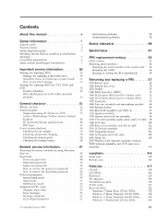
About this manual v Safety information 1 General safety 2 Electrical safety 3 Safety inspection guide 5 Handling devices that are sensitive to electrostatic discharge 6 Grounding requirements 6 Safety notices (multilingual translations) . . . . . 7 Important service information . . . . . 29 - Lenovo 01965DU | User Manual - Page 6
Windows 7 Professional (64 bit) DVDs . . . . 135 Common service tools 136 Notices 137 Trademarks 138 iv ThinkPad Edge 13″ and E30 Hardware Maintenance Manual - Lenovo 01965DU | User Manual - Page 7
trained service technicians who are familiar with ThinkPad products. Use this manual along with the advanced diagnostic tests to troubleshoot problems effectively. Before servicing a ThinkPad product, be sure to read all the information under "Safety information" on page 1. © Copyright Lenovo 2009 - Lenovo 01965DU | User Manual - Page 8
vi ThinkPad Edge 13″ and E30 Hardware Maintenance Manual - Lenovo 01965DU | User Manual - Page 9
presents following safety information that you need to be familiar with before you service a ThinkPad Notebook. v "General safety" on page 2 v "Electrical safety" on page 3 v "Safety inspection guide" on page 5 v "Handling devices that are sensitive to electrostatic discharge" on page 6 v "Grounding - Lenovo 01965DU | User Manual - Page 10
v Place removed covers and other parts in a safe place, away from all personnel, while you are servicing the machine. v Keep your toolcase away from walk areas so that other people will not trip over or cover them with labels or stickers. 2 ThinkPad Edge 13″ and E30 Hardware Maintenance Manual - Lenovo 01965DU | User Manual - Page 11
the room emergency power-off (EPO) switch, disconnecting switch, or electrical outlet. If an electrical accident occurs, you can then operate the switch or unplug safety precautions when you work with very high voltages; Instructions for these precautions are in the safety sections of maintenance - Lenovo 01965DU | User Manual - Page 12
is conductive; such touching can cause personal injury and machine damage. v Do not service the following parts with the power on when they are removed from their normal operating Switch off power. - Send another person to get medical aid. 4 ThinkPad Edge 13″ and E30 Hardware Maintenance Manual - Lenovo 01965DU | User Manual - Page 13
ThinkPad features or options not covered by this inspection guide . If any unsafe conditions are present, you must determine how serious the apparent hazard could be and whether you can continue without first correcting the problem every service task Power off the computer. Disconnect the power - Lenovo 01965DU | User Manual - Page 14
specific service computers. Grounding requirements Electrical grounding of the computer is required for operator safety and correct system function. Proper grounding of the electrical outlet can be verified by a certified electrician. 6 ThinkPad Edge 13″ and E30 Hardware Maintenance Manual - Lenovo 01965DU | User Manual - Page 15
Safety notices (multilingual translations) The safety notices in this section are provided in the following languages: v English v Arabic v Brazilian Portuguese v French v German v Hebrew v Japanese v Korean v Spanish v Traditional Chinese Safety information 7 - Lenovo 01965DU | User Manual - Page 16
other small parts are in place and are not left loose inside the computer. Verify this by shaking the computer and listening for rattling sounds. Metallic parts or metal flakes can cause any symptoms from the fluid are present after washing. 8 ThinkPad Edge 13″ and E30 Hardware Maintenance Manual - Lenovo 01965DU | User Manual - Page 17
burn personnel or combustible materials. DANGER Unless hot swap is allowed for the FRU being replaced, do as follows before removing it: power off the computer, unplug all power cords from electrical outlets, remove the battery pack, and disconnect any interconnecting cables. Safety information 9 - Lenovo 01965DU | User Manual - Page 18
10 ThinkPad Edge 13″ and E30 Hardware Maintenance Manual - Lenovo 01965DU | User Manual - Page 19
Safety information 11 - Lenovo 01965DU | User Manual - Page 20
, lave as áreas afetadas imediatamente com água durante pelo menos 15 minutos. Procure cuidados médicos se algum sintoma causado pelo fluido surgir após a lavagem. 12 ThinkPad Edge 13″ and E30 Hardware Maintenance Manual - Lenovo 01965DU | User Manual - Page 21
PERIGO Embora as principais baterias possuam baixa voltagem, uma bateria em curto-circuito ou aterrada pode produzir corrente o bastante para queimar materiais de pessoal ou inflamáveis. PERIGO A menos que uma hot swap seja permitida para a FRU que está sendo substituída, faça o seguinte antes de - Lenovo 01965DU | User Manual - Page 22
mains une partie du fluide, rincez-les abondamment pendant au moins quinze minutes. Consultez un médecin si des symptômes persistent après le lavage. 14 ThinkPad Edge 13″ and E30 Hardware Maintenance Manual - Lenovo 01965DU | User Manual - Page 23
DANGER Bien que le voltage des batteries principales soit peu élevé, le court-circuit ou la mise à la masse d'une batterie peut produire suffisamment de courant pour brûler des matériaux combustibles ou causer des brûlures corporelles graves. DANGER Si le remplacement à chaud n'est pas autorisé pour - Lenovo 01965DU | User Manual - Page 24
Schrauben, Federn oder andere Kleinteile fehlen oder im Gehäuse vergessen wurden. Der Computer muß geschüttelt und auf Klappergeräusche geprüft werden. Metallteile oder-splitter falscher Batterien kann zu Entzündung oder Explosion führen. 16 ThinkPad Edge 13″ and E30 Hardware Maintenance Manual - Lenovo 01965DU | User Manual - Page 25
Entsorgung die örtlichen Bestimmungen für Sondermüll beachten. Der LCD-Bildschirm besteht aus Glas und kann zerbrechen, wenn er unsachgemäß behandelt wird oder der Computer auf den Boden fällt. Wenn der Bildschirm beschädigt ist und die darin befindliche Flüssigkeit in Kontakt mit Haut und Augen ger - Lenovo 01965DU | User Manual - Page 26
18 ThinkPad Edge 13″ and E30 Hardware Maintenance Manual - Lenovo 01965DU | User Manual - Page 27
Safety information 19 - Lenovo 01965DU | User Manual - Page 28
20 ThinkPad Edge 13″ and E30 Hardware Maintenance Manual - Lenovo 01965DU | User Manual - Page 29
Safety information 21 - Lenovo 01965DU | User Manual - Page 30
22 ThinkPad Edge 13″ and E30 Hardware Maintenance Manual - Lenovo 01965DU | User Manual - Page 31
Safety information 23 - Lenovo 01965DU | User Manual - Page 32
inmediatamente las áreas afectadas con agua durante 15 minutos como mínimo. Obtenga atención medica si se presenta algún síntoma del fluido despues de lavarse. 24 ThinkPad Edge 13″ and E30 Hardware Maintenance Manual - Lenovo 01965DU | User Manual - Page 33
PELIGRO Aunque las baterías principales tienen un voltaje bajo, una batería cortocircuitada o con contacto a tierra puede producir la corriente suficiente como para quemar material combustible o provocar quemaduras en el personal. PELIGRO Salvo que se permita el intercambio en caliente para la - Lenovo 01965DU | User Manual - Page 34
26 ThinkPad Edge 13″ and E30 Hardware Maintenance Manual - Lenovo 01965DU | User Manual - Page 35
Safety information 27 - Lenovo 01965DU | User Manual - Page 36
28 ThinkPad Edge 13″ and E30 Hardware Maintenance Manual - Lenovo 01965DU | User Manual - Page 37
important service information that applies to all machine types supported by this manual: v support site http://www.lenovo.com/support System Disassembly/Reassembly videos that show the FRU removals or replacements for the Lenovo® authorized service technicians are available in the following support - Lenovo 01965DU | User Manual - Page 38
in this manual. After a system board is replaced, ensure that the latest BIOS is loaded to the system board before completing the service action. To download software fixes, drivers, and BIOS, do as follows: 1. Go to http://www.lenovo.com/support 2. Enter the product number of the computer or press - Lenovo 01965DU | User Manual - Page 39
cause false error codes. If no error code is displayed, see whether the error symptom is listed in the Symptom-to-FRU Index for the computer you are servicing. Important service information 31 - Lenovo 01965DU | User Manual - Page 40
configure an IBM® or a Lenovo solution from an eSite, and that has been negotiated between IBM or Lenovo and the customer. A unique 4-digit identify which FRUs are used to support CTO, CMV, and GAV products the following Web site: http://www.lenovo.com/support/site.wss/document.do?lndocid=LOOK- - Lenovo 01965DU | User Manual - Page 41
v eSupport can be accessed at the following Web site: http://www.lenovo.com/ support v To view the key commodities, click on PARTS INFORMATION, then PARTS by Category" select SERVICE PARTS. Under "Parts Information by Date" select SYSTEM SERVICE PARTS. The list of service parts by description, - Lenovo 01965DU | User Manual - Page 42
34 ThinkPad Edge 13″ and E30 Hardware Maintenance Manual - Lenovo 01965DU | User Manual - Page 43
ThinkPad model that supports the PC-Doctor® for DOS diagnostics program. Some descriptions might not apply to your particular computer. Before you go to the checkout guide, be sure to read the following important notes. Important notes: v Only certified trained personnel should service the computer - Lenovo 01965DU | User Manual - Page 44
computer password (making the computer unusable) v Sticky keys caused by spilling a liquid onto the keyboard v Use of an incorrect AC adapter on laptop products The following symptoms might indicate damage caused by nonwarranted activities: v Missing parts might be a symptom of unauthorized service - Lenovo 01965DU | User Manual - Page 45
following Web site: http:// www.lenovo.com/support To create the PC-Doctor diagnostic CD, follow the instructions on the Web site. For some possible configurations of the computer, PC-Doctor might not run correctly. To avoid this problem, you need to initialize the computer setup by use of the BIOS - Lenovo 01965DU | User Manual - Page 46
diagnostic CD to test the hardware features. Note: The PC-Doctor diagnostic CD does not support any external optical drives connected through USB devices or any others. To run the test, do as follows: 1. Turn off the computer. 2. Attach an external optical drive through the USB connector to the - Lenovo 01965DU | User Manual - Page 47
ThinkPad Notebook. If you have an external monitor attached to your computer, detach it before running PC-Doctor for DOS. v To test Digital Signature Chip, the security chip must be set to Active. 12. Run the applicable function test. 13. Follow the instructions on the screen. If there is a problem - Lenovo 01965DU | User Manual - Page 48
, advanced diagnostics, and diagnostic history. Note: The latest Lenovo ThinkVantage Toolbox is available at the following Web site: http://www.lenovo.com/support To install the latest Lenovo ThinkVantage Toolbox on the computer, follow the instructions on the Web site. To run this program, do - Lenovo 01965DU | User Manual - Page 49
Systemboard Power Diagnostics --> ThinkPad Devices --> AC Adapter drive, and then turn off the computer. 2. Turn on the computer. 3. While the message, "To problem. If the pointer stops after a short time, no service action is necessary. If enabling the TrackPoint does not correct the problem - Lenovo 01965DU | User Manual - Page 50
in the BIOS Setup Utility. If the Touch Pad is disabled, select Automatic to enable it. If enabling the Touch Pad does not correct the problem, continue with the following: v Interactive Tests --> Mouse 42 ThinkPad Edge 13″ and E30 Hardware Maintenance Manual - Lenovo 01965DU | User Manual - Page 51
pack supplies power when you turn on the computer. If you suspect a power problem, see the appropriate one of the following power Output voltage of pin no.2 of the AC adapter may different from the one you are servicing. 3. If the voltage is not correct, replace the AC adapter. 4. If the voltage - Lenovo 01965DU | User Manual - Page 52
: If the battery pack becomes hot, it may not be able to charge. Remove it from the computer and leave it at room temperature for a while. After it cools down, reinstall and recharge it. than +11.0 V dc after recharging, replace the battery. 44 ThinkPad Edge 13″ and E30 Hardware Maintenance Manual - Lenovo 01965DU | User Manual - Page 53
. If the resistance is correct, replace the system board. Checking the backup battery Do the following: 1. Power off the computer, and unplug the AC adapter from it. 2. Turn the computer upside down. 3. Remove the battery pack (see "1010 Battery pack" on page 68). 4. Remove the backup battery (see - Lenovo 01965DU | User Manual - Page 54
46 ThinkPad Edge 13″ and E30 Hardware Maintenance Manual - Lenovo 01965DU | User Manual - Page 55
53 Service Web site: When the latest maintenance diskette and the system program service diskette become available, they will be posted on http://www.lenovo.com disc set consists of the user instructions and the following set of DVDs to restore the computer to the original factory configuration. - Lenovo 01965DU | User Manual - Page 56
3. Press F10 to save the Setup Utility configuration changes. Follow the instructions on the screen to begin the recovery process. 4. Select your language the computer is turned on. The computer does not start until the password is entered. 48 ThinkPad Edge 13″ and E30 Hardware Maintenance Manual - Lenovo 01965DU | User Manual - Page 57
set. If it has, it can be used for access to the hard disk drive. If no master HDP is available, neither Lenovo nor Lenovo authorized service technicians provide any services to reset either the user or the master HDP, or to recover data from the hard disk drive. The hard disk drive can - Lenovo 01965DU | User Manual - Page 58
service technician: 1. Turn on the computer. 2. When the ThinkPad logo comes up, immediately press F1 to enter BIOS Setup Utility. For models supporting be made available to the service technician, neither Lenovo nor Lenovo authorized service technicians provide any services to reset the user HDPs - Lenovo 01965DU | User Manual - Page 59
7. Type the current master HDP in the Enter Current Password field. then leave the Enter New Password field blank, and press Enter twice. 8. Press F10. 9. Select Yes in the Setup Configuration window. Both user HDP and master HDP will have been removed. Related service information 51 - Lenovo 01965DU | User Manual - Page 60
Power Manager Battery Gauge in the task bar. 2. Select Power off display. Sleep mode When the computer enters sleep mode, the following events occur in addition to what occurs in screen blank mode: v The power button for more than 4 seconds. 52 ThinkPad Edge 13″ and E30 Hardware Maintenance Manual - Lenovo 01965DU | User Manual - Page 61
the problem, put the original part back in the computer. Do not replace a nondefective FRU. This index can also help you determine, during regular servicing, what "Intermittent problems" on page 58. Note: For a device not supported by diagnostic codes in the ThinkPad Notebooks, see the manual for - Lenovo 01965DU | User Manual - Page 62
board. 0271 Date and time error-Neither the date nor the time is set in the computer. (two short beeps) Run BIOS Setup Utility to reset the time and date. 0280 Previous System cache error. (two short beeps) 1. CPU. 2. System board. 54 ThinkPad Edge 13″ and E30 Hardware Maintenance Manual - Lenovo 01965DU | User Manual - Page 63
. 1. DIMM. 2. System board. 1. DIMM. 2. System board. 1. DIMM. 2. System board. 1. Remove the Mini PCI network card. 2. System board. 1. Remove the wireless WAN card. 2. System board. Related service information 55 - Lenovo 01965DU | User Manual - Page 64
Enter to load the default setting. Then save the current setting by pressing F10, and restart the computer. No-beep symptoms Table 4. No-beep symptoms Symptom or error FRU or action, in sequence No set. Type the password and press Enter. 56 ThinkPad Edge 13″ and E30 Hardware Maintenance Manual - Lenovo 01965DU | User Manual - Page 65
LCD for the notebook computer contains many thin-film transistors (TFTs). The presence of a small number of dots that are missing, discolored, or always lighted is characteristic of TFT LCD technology, but excessive pixel problems can cause viewing concerns. If the LCD you are servicing has two or - Lenovo 01965DU | User Manual - Page 66
If the problem does not recur, reconnect the removed devices one at a time until you find the failing FRU. 7. If the problem remains, replace the following FRUs one at a time (do not replace a nondefective FRU): a. System board b. LCD assembly 58 ThinkPad Edge 13″ and E30 Hardware Maintenance Manual - Lenovo 01965DU | User Manual - Page 67
This chapter presents the system status indicators that show the status of the computer. 1 2 3 4 Table 6. Status indicators Indicator Meaning 1 On- connected. If a battery is installed on the computer, it is charged when this indicator is on. Off: The AC adapter is not connected. © - Lenovo 01965DU | User Manual - Page 68
model. Red: The computer is on (in normal mode). Fast blinking red: The computer is entering sleep (standby) or hibernation mode. Slow blinking red: The computer is in sleep (standby) mode. Off: The computer is off or in hibernation mode. 60 ThinkPad Edge 13″ and E30 Hardware Maintenance Manual - Lenovo 01965DU | User Manual - Page 69
computer, the sound will remain muted when you turn on the computer Computer display only (LCD) v Computer display and external monitor (same image) v Computer computer display and an external monitor, the Win+P key combination is also available. The computer F8) The computer display becomes brighter - Lenovo 01965DU | User Manual - Page 70
the power state of each feature in the list. Note: To use this function, following device drivers must be installed on the computer beforehand: v Power Management driver v OnScreen Display Utility v Wireless device drivers Previous For Multimedia control. track/scene (F10) Play/pause (F11) Next - Lenovo 01965DU | User Manual - Page 71
replacing parts. Read this chapter carefully before replacing any FRU. Screw notices Loose screws can cause a reliability problem. In the ThinkPad Notebook, this problem is addressed with special nylon-coated screws that have the following characteristics: v They maintain tight connections. v They - Lenovo 01965DU | User Manual - Page 72
number by doing the following: 1. Install the LENOVO ThinkPad Hardware Maintenance Diskette Version 1.76 or later and restart the computer. 2. From the main menu, select 1. Set System Identification. 3. Select 1. Add S/N data from EEPROM. Follow the instructions on the screen. If the MTM and Product - Lenovo 01965DU | User Manual - Page 73
or later. 1. Insert the LENOVO ThinkPad Hardware Maintenance Diskette Version 1.76 or later, and restart the computer. 2. From the main menu, select 6. Set ECA Information. 3. To read ECA information, select 2. Read ECA/rework number from EEPROM and follow the instruction. 4. To read box build date - Lenovo 01965DU | User Manual - Page 74
66 ThinkPad Edge 13″ and E30 Hardware Maintenance Manual - Lenovo 01965DU | User Manual - Page 75
observe the following general rules: 1. Do not try to service any computer unless you have been trained and certified. An untrained person Before removing any FRU, turn off the computer, unplug all power cords from electrical outlets, remove the battery pack, and then Copyright Lenovo 2009 67 - Lenovo 01965DU | User Manual - Page 76
a possible safety issue. If ThinkVantage Toolbox is not installed in the computer, the customer should download this program before a non-physically damaged battery pack parts list for your computer. Any other battery could ignite or explode. 68 ThinkPad Edge 13″ and E30 Hardware Maintenance Manual - Lenovo 01965DU | User Manual - Page 77
Table 8. Removal steps of battery pack (continued) Unlock the battery latch 1 . Holding the battery latch in the unlocked position 2 , remove the battery pack in the direction shown by arrow 3 . 1 2 3 When installing: Install the battery pack in the slot, and then make sure that the battery - Lenovo 01965DU | User Manual - Page 78
not remove them. 1 1 1 2 1 1 When installing: Make sure that all the projections of the cover are attached firmly to the frame. Then secure the screws. 70 ThinkPad Edge 13″ and E30 Hardware Maintenance Manual - Lenovo 01965DU | User Manual - Page 79
Note: Applying label to the bottom slot cover When you replace the cover, following label needs to be peeled off from the old cover, and needs to be put on the new cover: 1 Asset tag label For the label location, refer the following figure: 1 Removing and replacing a FRU 71 - Lenovo 01965DU | User Manual - Page 80
70 Table 10. Removal steps of DIMM 1 2 1 a b Note: If only one DIMM is used on the computer you are servicing, the card must be installed in SLOT-0 ( a ), but not in SLOT-1 ( b ). When installing: Insert slot and does not move easily. 72 ThinkPad Edge 13″ and E30 Hardware Maintenance Manual - Lenovo 01965DU | User Manual - Page 81
1040 Hard disk drive (HDD) For access, remove these FRUs in order: v "1010 Battery pack" on page 68 v "1020 Bottom slot cover" on page 70 Attention: v Do not drop the drive or apply any physical shock to it. The drive is sensitive to physical shock. Improper handling can cause damage and permanent - Lenovo 01965DU | User Manual - Page 82
Table 11. Removal steps of HDD (continued) 2 3 When installing: Make sure that the HDD connector is attached firmly. 74 ThinkPad Edge 13″ and E30 Hardware Maintenance Manual - Lenovo 01965DU | User Manual - Page 83
1050 PCI Express Mini Card for wireless LAN For access, remove these FRUs in order: v "1010 Battery pack" on page 68 v "1020 Bottom slot cover" on page 70 Table 12. Removal steps of PCI Express Mini Card for wireless LAN In step 1 , unplug the jacks by using the removal tool antenna RF connector - Lenovo 01965DU | User Manual - Page 84
Table 12. Removal steps of PCI Express Mini Card for wireless LAN (continued) 3 When installing: Plug the gray cable into the jack marked MAIN or M, and the black cable into the jack marked AUX or A on the card. 76 ThinkPad Edge 13″ and E30 Hardware Maintenance Manual - Lenovo 01965DU | User Manual - Page 85
1060 PCI Express Mini Card for wireless WAN For access, remove these FRUs in order: v "1010 Battery pack" on page 68 v "1020 Bottom slot cover" on page 70 Table 13. Removal steps of PCI Express Mini Card for wireless WAN In step 1 , unplug the jacks by using the removal tool antenna RF connector - Lenovo 01965DU | User Manual - Page 86
Table 13. Removal steps of PCI Express Mini Card for wireless WAN (continued) 3 Note: Plug the red cable into the jack marked MAIN, and the blue cable into the jack marked AUX on the card. 78 ThinkPad Edge 13″ and E30 Hardware Maintenance Manual - Lenovo 01965DU | User Manual - Page 87
1070 Keyboard For access, remove these FRUs in order: v "1010 Battery pack" on page 68 v "1020 Bottom slot cover" on page 70 Table 14. Removal steps of keyboard 1 1 Step 1 Screw (quantity) M2 × 5 mm, wafer-head, nylon-coated (2) Color Black Torque 0.181 Nm (1.85 kgfcm) In step 2 , by using a - Lenovo 01965DU | User Manual - Page 88
Table 14. Removal steps of keyboard (continued) 3 5 6 7 8 7 4 80 ThinkPad Edge 13″ and E30 Hardware Maintenance Manual - Lenovo 01965DU | User Manual - Page 89
keyboard front edges are under the frame as shown in this figure. 3. Secure the keyboard by tightening the screws from the bottom side of the computer. Removing and replacing a FRU 81 - Lenovo 01965DU | User Manual - Page 90
of top case assembly and microphone module 1 1 1 1 1 1 1 1 1 1 Step 1 Screw (quantity) Color M2 × 5 mm, wafer-head, nylon-coated (10) Black Torque 0.181 Nm (1.85 kgfcm) 82 ThinkPad Edge 13″ and E30 Hardware Maintenance Manual - Lenovo 01965DU | User Manual - Page 91
Table 16. Removal steps of top case assembly and microphone module (continued) 2 2 2 2 2 2 Step 2 Screw (quantity) M2 × 3 mm, wafer-head, nylon-coated (6) Color Black Torque 0.181 Nm (1.85 kgfcm) 3 3 3 Step 3 Screw (quantity) M2 × 3 mm, wafer-head, nylon-coated (3) Color Black Torque 0. - Lenovo 01965DU | User Manual - Page 92
Table 16. Removal steps of top case assembly and microphone module (continued) 4 5 6 7 8 When installing: Make sure that the connectors are attached firmly. 84 ThinkPad Edge 13″ and E30 Hardware Maintenance Manual - Lenovo 01965DU | User Manual - Page 93
Table 16. Removal steps of top case assembly and microphone module (continued) In step 5 , push the top case assembly out from the frame by using a plastic pry tool as shown in this figure. 9 9 9 9 9 10 9 9 9 9 9 12 12 13 14 11 Removing and replacing a FRU 85 - Lenovo 01965DU | User Manual - Page 94
and microphone module" on page 82 Table 17. Removal steps of backup battery DANGER Use only the battery specified in the parts list for your computer. Any other battery could ignite or explode. 1 2 When installing: Make sure that the connector is attached firmly. 86 - Lenovo 01965DU | User Manual - Page 95
1100 Bluetooth daughter card (BDC-2) v "1010 Battery pack" on page 68 v "1020 Bottom slot cover" on page 70 v "1070 Keyboard" on page 79 v "1080 Top case assembly and microphone module" on page 82 Table 18. Removal steps of BDC-2 1 2 Step 1 Screw (quantity) M2 × 3 mm, wafer-head, nylon-coated (1) - Lenovo 01965DU | User Manual - Page 96
82 Table 19. Removal steps of speaker assembly 1 1 1 1 Step 2 Screw (quantity) M2 × 3 mm, wafer-head, nylon-coated (4) Color Black Torque 0.181 Nm (1.85 kgfcm) 88 ThinkPad Edge 13″ and E30 Hardware Maintenance Manual - Lenovo 01965DU | User Manual - Page 97
Table 19. Removal steps of speaker assembly (continued) 2 3 3 Cable routing: Make sure that the connector is attached firmly and you route the cable as shown in this figure. Removing and replacing a FRU 89 - Lenovo 01965DU | User Manual - Page 98
1. Place the computer on a horizontal surface. 2. Run Diagnostics --> ThinkPad Devices --> HDD Active Protection Test. Attention: Do not apply physical shock to the computer while the test -2)" on page 87 v "1110 Speaker assembly" on page 88 90 ThinkPad Edge 13″ and E30 Hardware Maintenance Manual - Lenovo 01965DU | User Manual - Page 99
steps of system board and fan assembly Following components soldered on the top side of the system board are extremely sensitive. When you service the system board, avoid any kind of rough handling. For CULV (Customer Ultra-Low Voltage) models: a Accelerometer chip for the HDD Active Protection - Lenovo 01965DU | User Manual - Page 100
Table 20. Removal steps of system board and fan assembly (continued) For AMD models: a CPU b North Bridge c South Bridge d Accelerometer chip for the HDD Active Protection System a b d c 92 ThinkPad Edge 13″ and E30 Hardware Maintenance Manual - Lenovo 01965DU | User Manual - Page 101
Table 20. Removal steps of system board and fan assembly (continued) 2 2 1 1 1 Step 1 Screw (quantity) M2 × 3 mm, wafer-head, nylon-coated (3) Color Black Torque 0.181 Nm (1.85 kgfcm) Note: Loosen the screws 2 , but do not remove them. Removing and replacing a FRU 93 - Lenovo 01965DU | User Manual - Page 102
Table 20. Removal steps of system board and fan assembly (continued) 3 4 When installing: Make sure that the connectors are attached firmly. 94 ThinkPad Edge 13″ and E30 Hardware Maintenance Manual - Lenovo 01965DU | User Manual - Page 103
board and fan assembly (continued) a 5 8 7 6 When installing: Attach the system board so that the battery pins of the system board are attached firmly to the guide hole of the base cover as shown in a in this figure. Make sure that the connectors are attached firmly. Removing and replacing a FRU 95 - Lenovo 01965DU | User Manual - Page 104
Table 20. Removal steps of system board and fan assembly (continued) Note: Loosen the screws 9 , but do not remove them. 9 9 10 11 96 ThinkPad Edge 13″ and E30 Hardware Maintenance Manual - Lenovo 01965DU | User Manual - Page 105
continued) When installing: v Before you attach the fan assembly to the computer, apply thermal grease, at an amount of 0.2 grams, on the . Either too much or too less application of grease can cause a thermal problem due to imperfect contact with a component. You need to peel the thin film off from - Lenovo 01965DU | User Manual - Page 106
steps of I/O card assembly, audio cable, and I/O cable 1 1 1 1 2 Step 2 Screw (quantity) M2 × 3 mm, wafer-head, nylon-coated (1) Color Black Torque 0.181 Nm (1.85 kgfcm) 4 3 98 ThinkPad Edge 13″ and E30 Hardware Maintenance Manual - Lenovo 01965DU | User Manual - Page 107
Table 21. Removal steps of I/O card assembly, audio cable, and I/O cable (continued) 6 5 Cable routing: Make sure that the connectors are attached firmly and you route the cables as shown in this figure. Removing and replacing a FRU 99 - Lenovo 01965DU | User Manual - Page 108
90 Table 22. Removal steps of LCD unit 2 2 1 1 1 1 1 2 2 Step 2 Screw (quantity) M2 × 5 mm, wafer-head, nylon-coated (2) Color Black Torque 0.181 Nm (1.85 kgfcm) 100 ThinkPad Edge 13″ and E30 Hardware Maintenance Manual - Lenovo 01965DU | User Manual - Page 109
Table 22. Removal steps of LCD unit (continued) 3 3 Cable routing: Make sure that the cables are attached to the cable guides as shown in this figure. When you route the cables, make sure that they are not subjected to any tension. Tension could cause the cables - Lenovo 01965DU | User Manual - Page 110
and fan assembly" on page 90 v "1140 LCD unit" on page 100 Table 23. Removal steps of base cover assembly and DC-in cable 1 1 1 1 2 102 ThinkPad Edge 13″ and E30 Hardware Maintenance Manual - Lenovo 01965DU | User Manual - Page 111
Table 23. Removal steps of base cover assembly and DC-in cable (continued) Cable routing: Make sure that the cable is attached to the cable guides as shown in this figure. When you route the cables, make sure that they are not subjected to any tension. Tension could cause the cables - Lenovo 01965DU | User Manual - Page 112
and apply them to the new base cover. For the location of each label, refer the following figure: 1 2 3 4 15 14 13 5 12 11 10 9 8 7 6 104 ThinkPad Edge 13″ and E30 Hardware Maintenance Manual - Lenovo 01965DU | User Manual - Page 113
2010 LCD bezel assembly For access, remove this FRU: v "1010 Battery pack" on page 68 Table 24. Removal steps of LCD bezel assembly 1 1 1 1 Step 1 Screw cap Screw (quantity) M2 × 3 mm, wafer-head, nylon-coated (4) Color Black Torque 0.181 Nm (1.85 kgfcm) 2 2 2 2 2 2 2 2 2 2 Removing and - Lenovo 01965DU | User Manual - Page 114
" on page 105 Table 25. Removal steps of integrated camera 1 2 When installing: Make sure that the connector of the integrated camera is attached firmly. 106 ThinkPad Edge 13″ and E30 Hardware Maintenance Manual - Lenovo 01965DU | User Manual - Page 115
2030 LCD panel and LCD cable For access, remove these FRUs in order: v "1010 Battery pack" on page 68 v "1020 Bottom slot cover" on page 70 v "1040 Hard disk drive (HDD)" on page 73 v "1050 PCI Express Mini Card for wireless LAN" on page 75 v "1060 PCI Express Mini Card for wireless WAN" on page 77 - Lenovo 01965DU | User Manual - Page 116
Table 26. Removal steps of LCD panel and LCD cable (continued) 2 4 3 8 5 6 7 108 ThinkPad Edge 13″ and E30 Hardware Maintenance Manual - Lenovo 01965DU | User Manual - Page 117
Table 26. Removal steps of LCD panel and LCD cable (continued) 10 Removing and replacing a FRU 109 - Lenovo 01965DU | User Manual - Page 118
107 Table 27. Removal steps of hinge kit 2 1 1 2 Step 2 Screw (quantity) M2 × 3 mm, wafer-head, nylon-coated (2) Color Black Torque 0.181 Nm (1.85 kgfcm) 110 ThinkPad Edge 13″ and E30 Hardware Maintenance Manual - Lenovo 01965DU | User Manual - Page 119
Table 27. Removal steps of hinge kit (continued) 3 3 Removing and replacing a FRU 111 - Lenovo 01965DU | User Manual - Page 120
v "2070 Hinge kit" on page 110 Table 28. Removal steps of wireless LAN antenna assembly, wireless WAN antenna assembly, and LCD rear cover assembly 1 2 2 2 2 1 1 1 112 ThinkPad Edge 13″ and E30 Hardware Maintenance Manual - Lenovo 01965DU | User Manual - Page 121
route the cables, make sure that they are not subjected to any tension. Tension could cause the cables to be damaged by the cable guides, or a wire to be broken. a : Wireless LAN MAIN antenna (gray) b : Wireless WAN MAIN antenna (red) c : Wireless WAN AUX antenna (blue) d : Wireless LAN AUX antenna - Lenovo 01965DU | User Manual - Page 122
114 ThinkPad Edge 13″ and E30 Hardware Maintenance Manual - Lenovo 01965DU | User Manual - Page 123
Locations Front view This chapter presents the location of ThinkPad Edge 13″ features and hardware. 1 Integrated camera (for some models) 2 Power switch 3 AC power connector 4 12 Touch pad 13 UltraNav 14 Built-in microphone 1 14 2 12 11 13 10 9 3 4 5 6 7 8 © Copyright Lenovo 2009 115 - Lenovo 01965DU | User Manual - Page 124
Bottom view 1 2 3 4 5 6 7 8 9 Battery pack latch Battery pack Security keyhole External monitor connector HDMI port RJ-45 (Ethernet) connector USB connector Built-in stereo speakers HDD slot door 1 2 1 3 9 4 5 6 8 7 116 ThinkPad Edge 13″ and E30 Hardware Maintenance Manual - Lenovo 01965DU | User Manual - Page 125
v "Recovery discs" on page 132 v "Common service tools" on page 136 Notes: v Each FRU service CRU; two asterisks (**) means that the part is an Optional-service CRU. ThinkPad Notebooks contain the following types of CRUs: Self-service -service CRUs These CRUs are isolated parts within the computer - Lenovo 01965DU | User Manual - Page 126
Overall 1 21 2 3 20 4 19 5 18 6 7 17 8 16 9 10 15 11 14 12 13 118 ThinkPad Edge 13″ and E30 Hardware Maintenance Manual - Lenovo 01965DU | User Manual - Page 127
for China telecom v 0196-CTO v 0197-CTO v 0492-CTO 60Y3227 5 ThinkPad 11b/g/n Wireless LAN Mini-PCI Express Adapter II 43Y6553 v 0196-CTO, 27x , 32x, 33x, 34x, 35x, 36x, 37x, 38x, 39x, 3Ax, 3Bx, 3Cx 5 ThinkPad 11b/g/n Wireless LAN Mini-PCI Express Adapter II 60Y3177 v 0196-CTO, 27x, 28x, 29x, - Lenovo 01965DU | User Manual - Page 128
, 38x, 39x, 3Ax, 3Cx, 3Dx, 3Ex, 3Fx, 3Gx, 3Hx, 3Jx, 3Kx, 52x 7 I/O cable 45M2905 8 Function board assembly 63Y2127 9 DC-in cable 45M2901 CRU ID ** ** ** ** ** ** ** N N N 120 ThinkPad Edge 13″ and E30 Hardware Maintenance Manual - Lenovo 01965DU | User Manual - Page 129
Table 29. Parts list-Overall (continued) No. FRU (Overall) FRU no. 10 Battery pack, Li-ion (4 cell) 73 42T4805 v 0196-CTO, 23x, 27x, 2Cx, 2Ex, 2Fx, 2Hx, 2Jx, 2Ux, 2Xx, 3Jx, 3Nx, 3Px, 3Rx, 3Sx, 3Tx, 3Ux, 47x, 48x, 49x, 4Ax, 4Bx, 4Cx, 4Dx, 4Ex, 4Gx, 4Jx, 4Lx, 4Mx, 4Nx, 4Px, 4Yx v 0197-CTO, 27x, - Lenovo 01965DU | User Manual - Page 130
, 28x, 29x, 2Ax, 2Bx, 2Cx, 2Gx, 2Lx, 2Qx, 2Tx, 2Ux, 2Vx, 2Xx, 2Yx, 2Zx, 34x, 37x, 3Dx, 3Ex, 3Fx, 3Gx, 3Hx, 3Jx CRU ID ** ** ** ** ** ** ** 122 ThinkPad Edge 13″ and E30 Hardware Maintenance Manual - Lenovo 01965DU | User Manual - Page 131
Table 29. Parts list-Overall (continued) No. FRU (Overall) FRU no. 14 SATA hard disk drive, 320 GB, 5,400 rpm 60Y4751 v 0196-CTO, 22x, 28x, 2Ax, 2Bx, 2Cx, 2Ex, 2Fx, 2Hx, 2Jx, 2Lx, 2Mx, 2Px, 2Qx, 2Rx, 2Tx, 2Ux, 2Zx, 32x, 33x, 34x, 35x, 36x, 3Bx, 3Ex, 3Fx, 3Gx, 3Nx, 3Px, 3Rx, 3Sx, 3Tx, 3Yx, 3Zx, - Lenovo 01965DU | User Manual - Page 132
, 5Ux, 5Vx, 5Wx, 5Xx, 6Bx, 6Cx, 6Dx, 6Ex, 6Gx, 6Hx, 6Jx, 6Kx, 6Lx, 6Mx, 6Nx, 6Rx, 6Sx, 6Tx, 6Ux, 6Zx, 72x, 73x CRU ID ** ** ** ** N N N N N N N N N 124 ThinkPad Edge 13″ and E30 Hardware Maintenance Manual - Lenovo 01965DU | User Manual - Page 133
Table 29. Parts list-Overall (continued) No. FRU (Overall) FRU no. 18 System board assembly, AMD Athlon Neo X2 Single-Core MV-40 v 0197-CTO 60Y5707 19 Bluetooth daughter card (BDC-2.1) 60Y3199 v 0196-CTO, 22x, 23x, 24x, 25x, 26x, 27x, 28x, 29x, 2Ax, 2Bx, 2Cx, 2Dx, 2Ex, 2Fx, 2Gx, 2Hx, 2Jx, 2Kx - Lenovo 01965DU | User Manual - Page 134
LCD FRUs 8 7 6 126 ThinkPad Edge 13″ and E30 Hardware Maintenance Manual 1 2 3 4 5 - Lenovo 01965DU | User Manual - Page 135
Table 30. Parts list-13.3-inch HD LED-backlight LCD No. FRU (13.3-inch HD LED-backlight LCD) FRU no. 1 LCD bezel assembly 60Y5527 2 Hinges, black 60Y5525 v 0196-CTO, 22x, 24x, 25x, 26x, 27x, 28x, 2Ax, 2Bx, 2Cx, 2Dx, 2Ex, 2Fx, 2Gx, 2Hx, 2Mx, 2Px, 2Rx, 2Tx, 2Vx, 2Wx, 2Xx, 2Yx, 32x, 33x, 35x, - Lenovo 01965DU | User Manual - Page 136
) LED-backlight, glair 27R2437 8 LCD module, 13.3-inch HD LED-backlight, glair 27R2435 8 LCD module, 13.3-inch HD LED-backlight, glair 27R2439 CRU ID N N N N N N N N N N 128 ThinkPad Edge 13″ and E30 Hardware Maintenance Manual - Lenovo 01965DU | User Manual - Page 137
Keyboard Table 31. Parts list-Keyboard Language Arabic Belgian Brazilian Portuguese Bulgarian Canadian French (058) Canadian French (Acnor) Czech Danish Dutch Finnish, Swedish French German Greek (U.S. English and Greek layout) Hebrew Hungarian Icelandic Italian Japanese Kazakhstan Korean Latin - Lenovo 01965DU | User Manual - Page 138
(6) v M3 × 3.5 mm (black), wafer head (3) FRU no. 42T5282 42T4423 42T4419 CRU ID * FRU no. 42T5283 42T4421 42T4417 CRU ID * FRU no. 60Y5521 CRU ID N 130 ThinkPad Edge 13″ and E30 Hardware Maintenance Manual - Lenovo 01965DU | User Manual - Page 139
Power cords A ThinkPad power cord for a specific country or region is usually available only in that country or region: Table 35. Parts list-2-pin power cords Country or - Lenovo 01965DU | User Manual - Page 140
Russian Russian (English-enabled) Simplified Chinese Spanish Traditional Chinese Traditional Chinese (Hong Kong S.A.R.) P/N 58Y4054 58Y4064 58Y4058 58Y4060 58Y4059 58Y4055 58Y4061 58Y4056 58Y4057 CRU ID * 132 ThinkPad Edge 13″ and E30 Hardware Maintenance Manual - Lenovo 01965DU | User Manual - Page 141
Windows 7 Home Premium (64 bit) DVDs Windows 7 Home Premium (64 bit) is preinstalled as the operating system in the following models: v 0196-CTO, 2Ux, 3Qx, 3Rx, 3Sx, 3Tx, 3Ux, 4Cx v 0197-CTO, 25x, 27x, 29x, 2Ax, 2Cx, 2Dx, 2Mx, 2Px, 4Xx, 4Zx, 53x, 55x, 57x, 59x, 5Bx, 5Dx, 5Fx, 5Hx, 5Kx, 5Mx, 5Px, 5Rx - Lenovo 01965DU | User Manual - Page 142
-enabled) 58Y4083 Serbian-Latin 58Y4089 Simplified Chinese Slovak 58Y4067 58Y4086 Slovenian 58Y4087 Spanish 58Y4088 Traditional Chinese 58Y4068 Traditional Chinese (Hong Kong S.A.R.) 58Y4075 Turkish 58Y4090 134 ThinkPad Edge 13″ and E30 Hardware Maintenance Manual - Lenovo 01965DU | User Manual - Page 143
Windows 7 Professional (64 bit) DVDs Windows 7 Professional (64 bit) is preinstalled as the operating system in the following models: v 0196-CTO, 22x, 23x, 25x, 26x, 27x, 28x, 2Ax, 2Bx, 2Dx, 2Gx, 2Kx, 2Vx, 2Wx, 37x, 38x, 39x, 3Ax, 47x v 0197-CTO, 23x, 24x, 26x, 2Ex, 2Fx, 2Qx, 2Wx, 3Px, 3Qx, 3Sx, 4Sx - Lenovo 01965DU | User Manual - Page 144
tools Table 42. Parts list-Common service tools Tool P/N Screwdriver kit 95F3598 1/4″ drive spinner handle 1650840 diskette drive tool kit 27L3452 Test card for integrated Smart Card 42W7820 LENOVO ThinkPad Hardware Maintenance Diskette Version 1.76 or later - Note: Download the file - Lenovo 01965DU | User Manual - Page 145
and verify the operation of any other product, program, or service. Lenovo may have patents or pending patent applications covering subject matter described document are not intended for use in implantation or other life support applications where malfunction may result in injury or death to - Lenovo 01965DU | User Manual - Page 146
trademarks of Lenovo in the United States, other countries or both: Active Protection System Lenovo® Rescue and Recovery® ThinkPad® ThinkVantage® : Other company, product, or service names may be the trademarks or service marks of others. 138 ThinkPad Edge 13″ and E30 Hardware Maintenance Manual - Lenovo 01965DU | User Manual - Page 147
- Lenovo 01965DU | User Manual - Page 148
Part Number: 63Y0744 (1P) P/N: 63Y0744
-
 1
1 -
 2
2 -
 3
3 -
 4
4 -
 5
5 -
 6
6 -
 7
7 -
8
-
9
-
10
-
11
-
12
-
13
-
14
-
15
-
16
-
17
-
18
-
19
-
20
-
21
-
22
-
23
-
24
-
25
-
26
-
27
-
28
-
29
-
30
-
31
-
32
-
33
-
34
-
35
-
36
-
37
-
38
-
39
-
40
-
41
-
42
-
43
-
44
-
45
-
46
-
47
-
48
-
49
-
50
-
51
-
52
-
53
-
54
-
55
-
56
-
57
-
58
-
59
-
60
-
61
-
62
-
63
-
64
-
65
-
66
-
67
-
68
-
69
-
70
-
71
-
72
-
73
-
74
-
75
-
76
-
77
-
78
-
79
-
80
-
81
-
82
-
83
-
84
-
85
-
86
-
87
-
88
-
89
-
90
-
91
-
92
-
93
-
94
-
95
-
96
-
97
-
98
-
99
-
100
-
101
-
102
-
103
-
104
-
105
-
106
-
107
-
108
-
109
-
110
-
111
-
112
-
113
-
114
-
115
-
116
-
117
-
118
-
119
-
120
-
121
-
122
-
123
-
124
-
125
-
126
-
127
-
128
-
129
-
130
-
131
-
132
-
133
-
134
-
135
-
136
-
137
-
138
-
139
-
140
-
141
-
142
-
143
-
144
-
145
-
146
-
147
-
148
 |
 |

ThinkPad Edge 13
″
and E30
Hardware Maintenance Manual