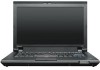
Lenovo 055335U Hardware Maintenance Manual
Lenovo 055335U Manual
 |
View all Lenovo 055335U manuals
Add to My Manuals
Save this manual to your list of manuals |
Lenovo 055335U manual content summary:
- Lenovo 055335U | Hardware Maintenance Manual - Page 1
Hardware Maintenance Manual ThinkPad L412 and L512 - Lenovo 055335U | Hardware Maintenance Manual - Page 2
and the product it supports, be sure to read the general information under Appendix A "Notices" on page 157. Fifth Edition (April 2013) © Copyright Lenovo 2011, 2013. LIMITED AND RESTRICTED RIGHTS NOTICE: If data or software is delivered pursuant a General Services Administration "GSA" contract, use - Lenovo 055335U | Hardware Maintenance Manual - Page 3
guide 28 System supporting the Lenovo ThinkVantage Toolbox program and the PC-Doctor for DOS diagnostics program 28 System supporting the Lenovo messages 46 No-beep symptoms 46 LCD-related symptoms 47 Intermittent problems 47 Undetermined problems 48 Chapter 5. Status indicators . . . . . - Lenovo 055335U | Hardware Maintenance Manual - Page 4
7 Professional (64 bit) DVDs. . . . 153 Windows Starter (32 bit) DVDs 154 Windows 7 Ultimate (32 bit) DVDs . . . . . 155 Windows 7 Ultimate (64 bit) DVDs . . . . . 155 Common service tools 156 Appendix A. Notices 157 Electronic emissions notices 158 Trademarks 158 ii Hardware Maintenance - Lenovo 055335U | Hardware Maintenance Manual - Page 5
this manual along with the advanced diagnostic tests to troubleshoot problems effectively. Before servicing a ThinkPad Notebook product, be sure to read all the information under Chapter 1 "Safety information" on page 1 and Chapter 2 "Important service information" on page 23. © Copyright Lenovo - Lenovo 055335U | Hardware Maintenance Manual - Page 6
iv Hardware Maintenance Manual - Lenovo 055335U | Hardware Maintenance Manual - Page 7
you need to be familiar with before you service a ThinkPad Notebook. • "General safety" on page 1 • "Electrical safety" on page 2 • "Safety inspection guide" on page 3 • "Handling devices that are Do not obstruct fan louvers or cover them with labels or stickers. © Copyright Lenovo 2011, 2013 1 - Lenovo 055335U | Hardware Maintenance Manual - Page 8
-off (EPO) switch, disconnecting switch, or electrical outlet. If an electrical accident occurs, you can then operate you work with very high voltages; Instructions for these precautions are in the personal injury and machine damage. • Do not service the following parts with the power on when they - Lenovo 055335U | Hardware Maintenance Manual - Page 9
ThinkPad features or options not covered by this inspection guide . If any unsafe conditions are present, you must determine how serious the apparent hazard could be and whether you can continue without first correcting the problem every service task Power off the computer. Disconnect the power - Lenovo 055335U | Hardware Maintenance Manual - Page 10
, to provide protection that meets the specific service requirement. Note: The use of a grounding computers. Grounding requirements Electrical grounding of the computer is required for operator safety and correct system function. Proper grounding of the electrical outlet Hardware Maintenance Manual - Lenovo 055335U | Hardware Maintenance Manual - Page 11
replacement, make sure all screws, springs, and other small parts are in place and are not left loose inside the computer. Verify this by shaking the computer and listening for rattling sounds. Metallic parts or metal flakes can cause electrical shorts. DANGER Some standby batteries contain a small - Lenovo 055335U | Hardware Maintenance Manual - Page 12
burn personnel or combustible materials. DANGER Unless hot swap is allowed for the FRU being replaced, do as follows before removing it: power off the computer, unplug all power cords from electrical outlets, remove the battery pack, and disconnect any interconnecting cables. 6 Hardware Maintenance - Lenovo 055335U | Hardware Maintenance Manual - Page 13
PERIGO Antes de ligar o computador após a substituição da FRU, certifique-se de que todos os parafusos, molas e outras peças pequenas estejam no lugar e não estejam soltos dentro do computador. Verifique isso sacudindo o computador e procurando ouvir sons de peças soltas. Peças metálicas ou lascas - Lenovo 055335U | Hardware Maintenance Manual - Page 14
de removê-la: desligue o computador, desconecte todos os cabos de energia das tomadas, remova o pacote de baterias e desconecte quaisquer cabos de interconexão. DANGER 8 Hardware Maintenance Manual - Lenovo 055335U | Hardware Maintenance Manual - Page 15
Avant de remettre l'ordinateur sous tension après remplacement d'une unité en clientèle, vérifiez que tous les ressorts, vis et autres pièces sont bien en place et bien fixées. Pour ce faire, secouez l'unité et assurez-vous qu'aucun bruit suspect ne se produit. Des pièces métalliques ou des copeaux - Lenovo 055335U | Hardware Maintenance Manual - Page 16
batterie et déconnectez tous les câbles d'interconnexion. VORSICHT Bevor nach einem FRU-Austausch der Computer wieder angeschlossen wird, muß sichergestellt werden, daß keine Schrauben, Federn oder andere Kleinteile fehlen zu Entzündung oder Explosion führen. VORSICHT 10 Hardware Maintenance Manual - Lenovo 055335U | Hardware Maintenance Manual - Page 17
Entsorgung die örtlichen Bestimmungen für Sondermüll beachten. Der LCD-Bildschirm besteht aus Glas und kann zerbrechen, wenn er unsachgemäß behandelt wird oder der Computer auf den Boden fällt. Wenn der Bildschirm beschädigt ist und die darin befindliche Flüssigkeit in Kontakt mit Haut und Augen ger - Lenovo 055335U | Hardware Maintenance Manual - Page 18
12 Hardware Maintenance Manual - Lenovo 055335U | Hardware Maintenance Manual - Page 19
Chapter 1. Safety information 13 - Lenovo 055335U | Hardware Maintenance Manual - Page 20
14 Hardware Maintenance Manual - Lenovo 055335U | Hardware Maintenance Manual - Page 21
Antes de encender el sistema despues de sustituir una FRU, compruebe que todos los tornillos, muelles y demás piezas pequeñas se encuentran en su sitio y no se encuentran sueltas dentro del sistema. Compruébelo agitando el sistema y escuchando los posibles ruidos que provocarían. Las piezas metá - Lenovo 055335U | Hardware Maintenance Manual - Page 22
sistema, desconecte todos los cables de alimentación de las tomas de alimentación eléctrica, extraiga la batería y desconecte los cables de interconexión. 16 Hardware Maintenance Manual - Lenovo 055335U | Hardware Maintenance Manual - Page 23
Laser compliance statement (multilingual translations) The laser compliance statements in this section are provided in the following languages: • English • Arabic • Brazilian Portuguese • French • German • Hebrew • Japanese • Korean • Spanish • Traditional Chinese Chapter 1. Safety information 17 - Lenovo 055335U | Hardware Maintenance Manual - Page 24
18 Hardware Maintenance Manual - Lenovo 055335U | Hardware Maintenance Manual - Page 25
Chapter 1. Safety information 19 - Lenovo 055335U | Hardware Maintenance Manual - Page 26
20 Hardware Maintenance Manual - Lenovo 055335U | Hardware Maintenance Manual - Page 27
Chapter 1. Safety information 21 - Lenovo 055335U | Hardware Maintenance Manual - Page 28
22 Hardware Maintenance Manual - Lenovo 055335U | Hardware Maintenance Manual - Page 29
service information that applies to all machine types supported by this manual contact the Lenovo Customer Support Center if they servicing FRUs: • If you are instructed to replace a FRU but the replacement does not correct the problem, reinstall the original FRU before you continue. • Some computers - Lenovo 055335U | Hardware Maintenance Manual - Page 30
symptom is listed in the Symptom-to-FRU Index for the computer you are servicing. Strategy for replacing FRUs for CTO, CMV, and GAV Model Variant (CMV) This is a unique configuration that has been negotiated between Lenovo and the customer. A unique 4-digit MT and 3-digit model is provided to Manual - Lenovo 055335U | Hardware Maintenance Manual - Page 31
• PEW can be accessed at the following Web site: http://www.lenovo.com/support/site.wss/document.do?lndocid=LOOK-WARNTY Select Warranty lookup. Input the MT the instructions on the screen to reach the Product and Parts Detail page. 2. Click the Parts Detail tab to view the list of service parts. - Lenovo 055335U | Hardware Maintenance Manual - Page 32
26 Hardware Maintenance Manual - Lenovo 055335U | Hardware Maintenance Manual - Page 33
ThinkPad model that supports the PC-Doctor® for DOS diagnostics program. Some descriptions might not apply to your particular computer. Before you go to the checkout guide, be sure to read the following important notes. Important notes: • Only certified trained personnel should service the computer - Lenovo 055335U | Hardware Maintenance Manual - Page 34
the diagnostic test or by repeating the operation. System supporting the Lenovo ThinkVantage Toolbox program and the PC-Doctor for DOS diagnostics program The section provides information about ThinkPad computers that support the Lenovo ThinkVantage® Toolbox program and the PC-Doctor® for DOS - Lenovo 055335U | Hardware Maintenance Manual - Page 35
supported as a startup device is installed to the computer you are servicing. 3. Turn on the computer. If the computer cannot be powered on, go to "Power system checkout" on page 35, and check the power sources. If an error code appears, go to "Symptom-to-FRU index" on page 44. 4. When the ThinkPad - Lenovo 055335U | Hardware Maintenance Manual - Page 36
be held down for at least 2 seconds; otherwise, it cannot be sensed. • Video Adapter test supports only the LCD display on the ThinkPad Notebook. If you have an external monitor attached to your computer, detach it before running PC-Doctor for DOS. • To test Digital Signature Chip, the security - Lenovo 055335U | Hardware Maintenance Manual - Page 37
Follow the instructions on the screen. Lenovo ThinkVantageToolbox also has problem determination aids that determine software and usage problems. For additional information about this program, see the Help for the program. PC-Doctor for Rescue and Recovery In some models of ThinkPad Notebook, the - Lenovo 055335U | Hardware Maintenance Manual - Page 38
the ThinkPad Notebook, detach it. Diagnostics ➙ ThinkPad Devices case, turn off and turn on the computer. Then, run this test again. 1. and then turn off the computer. 2. Turn on the computer. 3. While the message Diagnostics ➙ System Memory. 2. If the problem does not recur, return the DIMM to - Lenovo 055335U | Hardware Maintenance Manual - Page 39
test programs that enable you to troubleshoot and resolve computer internal storage and memory problems. Notes: • If the computer you are servicing is not installed with the Lenovo Solution Center program, you can download the quick test programs from the Lenovo Support Web site. • The two programs - Lenovo 055335U | Hardware Maintenance Manual - Page 40
be performed. 7. Follow the instructions on the screen to start the test. When a problem is detected, information messages will be displayed. Refer to the messages to troubleshoot the problem. UEFI diagnostic program A UEFI diagnostic program is preinstalled on the computer. It enables you to test - Lenovo 055335U | Hardware Maintenance Manual - Page 41
error code descriptions and troubleshooting hints. 2. Insert the CD into the optical drive. 3. Restart the computer. 4. When the ThinkPad logo is displayed, battery pack supplies power when you turn on the computer. If you suspect a power problem, see the appropriate one of the following power supply - Lenovo 055335U | Hardware Maintenance Manual - Page 42
ac adapter may different from the one you are servicing. 3. If the voltage is not correct, the system board. • If the problem persists, go to "FRU tests installed in the computer. Perform operational charge. Remove it from the computer and leave it at room 1. Power off the computer. 2. Remove the - Lenovo 055335U | Hardware Maintenance Manual - Page 43
. If the resistance is correct, replace the system board. Checking the backup battery Do the following: 1. Power off the computer, and unplug the ac adapter from it. 2. Turn the computer upside down. 3. Remove the battery pack (see "1010 Battery pack" on page 59). 4. Remove the backup battery (see - Lenovo 055335U | Hardware Maintenance Manual - Page 44
38 Hardware Maintenance Manual - Lenovo 055335U | Hardware Maintenance Manual - Page 45
Service Web site: When the latest maintenance diskette and the system program service diskette become available, they will be posted on http://www.lenovo disc set consists of the user instructions and the following set of DVDs to restore the computer to the original factory configuration. Operating - Lenovo 055335U | Hardware Maintenance Manual - Page 46
computer will restart into the Microsoft Windows desktop several times and you might experience periods when no activity is apparent on the screen for several minutes at a time. This is normal. 10. When the recovery process is complete, the Set Up Windows screen is displayed. Follow the instructions - Lenovo 055335U | Hardware Maintenance Manual - Page 47
If no master HDP is available, neither Lenovo nor Lenovo authorized service technicians provide any services to reset either the user or the master service technician: 1. Turn on the computer. 2. When the ThinkPad logo comes up, immediately press F1 to enter BIOS Setup Utility. For models supporting - Lenovo 055335U | Hardware Maintenance Manual - Page 48
the master HDP. Note: To check whether the ThinkPad Notebook you are servicing supports the Passphrase function, enter the BIOS Setup Utility timer in the operating system expires, the LCD backlight turns off. To put the computer into screen blank mode, do as follows: 1. Press Fn+F3. A panel Manual - Lenovo 055335U | Hardware Maintenance Manual - Page 49
computer computer enters the power-saving mode automatically. To cause the computer events, the computer automatically returns support the ring indicator (RI) resume by PC Card device.) • The time set on the resume timer elapses. Note: The computer the computer enters computer the computer goes computer - Lenovo 055335U | Hardware Maintenance Manual - Page 50
the problem, put the original part back in the computer. Do not replace a nondefective FRU. This index can also help you determine, during regular servicing, what "Intermittent problems" on page 47. Note: For a device not supported by diagnostic codes in the ThinkPad Notebooks, see the manual for - Lenovo 055335U | Hardware Maintenance Manual - Page 51
System board. 0271 Date and time error-Neither the date nor the time is set in the computer. (two short beeps) Run BIOS Setup Utility to reset the time and date. 0280 Previous boot 02F6 Software NMI failed (two short beeps) 1. DIMM. 2. System board. Chapter 4. Related service information 45 - Lenovo 055335U | Hardware Maintenance Manual - Page 52
and Enter to load the default setting. Then save the current setting by pressing F10, and restart the computer. No-beep symptoms Table 4. No-beep symptoms Symptom or error No beep, power-on indicator on, LCD 2. DIMM. 3. System board. 1. Reseat DIMM. 2. System board. 46 Hardware Maintenance Manual - Lenovo 055335U | Hardware Maintenance Manual - Page 53
the notebook computer contains many servicing has two or less visible defective pixels, it should not be considered faulty. However, if the LCD has three or more visible defective pixels, it will be deemed as defective by Lenovo and it should be replaced. Notes: • This policy applies to all ThinkPad - Lenovo 055335U | Hardware Maintenance Manual - Page 54
are supported by the computer. problem does not recur, reconnect the removed devices one at a time until you find the failing FRU. 7. If the problem remains, replace the following FRUs one at a time (do not replace a nondefective FRU): a. System board b. LCD assembly 48 Hardware Maintenance Manual - Lenovo 055335U | Hardware Maintenance Manual - Page 55
lit when the computer is in sleep (standby) mode. The wireless feature (802.11 standard or 802.11n) is on, and the radio link is ready for use. Data is being transmitted. Bluetooth wireless is on, and the radio link is ready for use. Data is being transmitted. © Copyright Lenovo 2011, 2013 - Lenovo 055335U | Hardware Maintenance Manual - Page 56
blinking color changes to green. The battery is charged between 0% to 5% of the capacity. An error has occurred in the battery. The battery of the computer is detached. 50 Hardware Maintenance Manual - Lenovo 055335U | Hardware Maintenance Manual - Page 57
appears. Fn+F4 Notes: 1. To use the Fn+F3 key combination, you must have the ThinkPad PM device driver installed on the computer. 2. If you have logged on with an administrator user ID, and you press Fn+F3, setting of the microphone mute button cannot be changed. © Copyright Lenovo 2011, 2013 51 - Lenovo 055335U | Hardware Maintenance Manual - Page 58
than four seconds. Note: To use Fn+F12 for hibernation, you must have the ThinkPad PM device driver installed on the computer. Turn the ThinkLight® on or off. Note: This function is supported only on the ThinkPad Notebooks that have the ThinkLight. The on or off status of the ThinkLight is shown - Lenovo 055335U | Hardware Maintenance Manual - Page 59
Table 7. Fn key combinations (continued) Key combination Description Fn+Pause Has the same function as the Break key. Fn+cursor keys These key combinations work with Windows Media Player. Fn+down arrow key works for the Play or Pause button, Fn+up arrow key for the Stop button, Fn+right arrow - Lenovo 055335U | Hardware Maintenance Manual - Page 60
54 Hardware Maintenance Manual - Lenovo 055335U | Hardware Maintenance Manual - Page 61
is your responsibility; you may request that Lenovo installs an Optional-service CRU according to the warranty service for your product. Where you are installing the CRU, Lenovo will ship the CRU to you. CRU information and replacement instructions are shipped with your product and are available - Lenovo 055335U | Hardware Maintenance Manual - Page 62
number by doing the following: 1. Install the LENOVO ThinkPad Hardware Maintenance Diskette Version 1.76 or later and restart the computer. 2. From the main menu, select 1. Set System Identification. 3. Select 1. Add S/N data from EEPROM. Follow the instructions on the screen. If the MTM and Product - Lenovo 055335U | Hardware Maintenance Manual - Page 63
or later. 1. Insert the LENOVO ThinkPad Hardware Maintenance Diskette Version 1.76 or later, and restart the computer. 2. From the main menu, select 6. Set ECA Information. 3. To read ECA information, select 2. Read ECA/rework number from EEPROM and follow the instruction. 4. To read box build date - Lenovo 055335U | Hardware Maintenance Manual - Page 64
58 Hardware Maintenance Manual - Lenovo 055335U | Hardware Maintenance Manual - Page 65
Lenovo installs an Optional-service CRU according to the warranty service for your product. Where you are installing the CRU, Lenovo will ship the CRU to you. CRU information and replacement instructions , turn off the computer, unplug all power cords from electrical outlets, remove the battery pack - Lenovo 055335U | Hardware Maintenance Manual - Page 66
or a customer is reporting a possible safety issue. If Lenovo ThinkVantage Toolbox or Lenovo System Toolbox is not installed in the computer, the customer should download this program before a non-physically damaged battery release lever is in the locked position. 60 Hardware Maintenance Manual - Lenovo 055335U | Hardware Maintenance Manual - Page 67
1020 ExpressCard blank bezel and Media Card blank bezel Removal steps of ExpressCard blank bezel When you press the ExpressCard blank bezel 1 , it pops out 2 . 1 2 When installing: Make sure that the bezel is correctly oriented as shown in this figure. Chapter 8. Removing and replacing a FRU 61 - Lenovo 055335U | Hardware Maintenance Manual - Page 68
shown in the following figure. 1030 Optical drive or travel cover For access, remove this FRU: • "1010 Battery pack" on page 59 62 Hardware Maintenance Manual - Lenovo 055335U | Hardware Maintenance Manual - Page 69
Removal steps of optical drive or travel cover 1 Step 1 Screw (quantity) M2 × 8 mm, flat-head, nylon-coated (1) 2 3 Color Black Torque 0.181 Nm (1.85 kgfcm) 1040 Thermal cover For access, remove this FRU: • "1010 Battery pack" on page 59 Chapter 8. Removing and replacing a FRU 63 - Lenovo 055335U | Hardware Maintenance Manual - Page 70
the fan motor located in the slot. It might cause damage to the fan assembly or the computer to mulfunction. 1050 Hard disk drive (HDD) assembly For access, remove these FRUs in order: possible. • Never remove the drive while the computer is operating or is in suspend mode. 64 Hardware Maintenance - Lenovo 055335U | Hardware Maintenance Manual - Page 71
Removal steps of HDD assembly 1 When installing: Make sure that the HDD is attached firmly. 2 a When installing: Do not apply excessive force to the HDD bracket a . To do so, you might bend or break it. 1060 DIMM For access, remove these FRUs in order: Chapter 8. Removing and replacing a FRU 65 - Lenovo 055335U | Hardware Maintenance Manual - Page 72
• "1040 Thermal cover" on page 63 Removal steps of DIMM 1 2 1 Note: If only one DIMM is used on the computer you are servicing, the card must be installed in SLOT-0 ( a : the lower slot), but not in SLOT-1 ( b : the upper " on page 59 • "1040 Thermal cover" on page 63 66 Hardware Maintenance Manual - Lenovo 055335U | Hardware Maintenance Manual - Page 73
excessive force to the fan motor. It might cause damage to the fan assembly or the computer to mulfunction. Removal steps of fan assembly 1 When installing: Make sure that the fan connector the screws in order. For ThinkPad L512: 2e 2d 3 2b 2f 2a 2c Chapter 8. Removing and replacing a FRU 67 - Lenovo 055335U | Hardware Maintenance Manual - Page 74
ThinkPad 85 kgfcm) 4 When installing: Before you attach the fan assembly to the computer, apply thermal grease, at an amount of 0.2 grams, on the parts marked too much or too less application of grease can cause a thermal problem due to imperfect contact with a component. For the new CPU thermal - Lenovo 055335U | Hardware Maintenance Manual - Page 75
Battery pack" on page 59 • "1040 Thermal cover" on page 63 • "1070 Fan assembly" on page 66 Attention: The CPU is extremely sensitive. When you service the CPU, avoid any kind of rough handling. Chapter 8. Removing and replacing a FRU 69 - Lenovo 055335U | Hardware Maintenance Manual - Page 76
shown by arrow a to secure the CPU. 1090 SIM slot cover For access, remove this FRU: • "1010 Battery pack" on page 59 70 Hardware Maintenance Manual - Lenovo 055335U | Hardware Maintenance Manual - Page 77
1 2 Some models might have the SIM card that the customer has been installed. If the computer you are servicing has the SIM card, remove it before you start the servicing. After you finish the servicing, make sure that you insert the card back into the slot firmly. Chapter 8. Removing and replacing - Lenovo 055335U | Hardware Maintenance Manual - Page 78
2 1 1100 Wireless WAN slot cover and PCI Express Mini Card for wireless WAN For access, remove this FRU: • "1010 Battery pack" on page 59 Removal steps of wireless WAN slot cover and PCI Express Mini Card for wireless WAN Note: Loosen the screw 1 . 1 72 Hardware Maintenance Manual - Lenovo 055335U | Hardware Maintenance Manual - Page 79
2 In step 3a and 3b , unplug the jacks by using the removal tool antenna RF connector (P/N: 08K7159) or pick the connectors with your fingers and gently unplug them in the direction of the arrow. 3b 3a 4 4 When installing: Plug the red cable 3a into the jack labeled MAIN , and the blue cable - Lenovo 055335U | Hardware Maintenance Manual - Page 80
, flat-head, nylon-coated (1) M2 × 5 mm, flat-head, nylon-coated (6) Color Black Black Torque 0.181 Nm (1.85 kgfcm) 0.181 Nm (1.85 kgfcm) 74 Hardware Maintenance Manual - Lenovo 055335U | Hardware Maintenance Manual - Page 81
the cables to the system board firmly. 2. Attach the palm rest so that the two small projections of the palm rest a firmly fit into the guide holes of the keyboard bezel as shown in this figure. Chapter 8. Removing and replacing a FRU 75 - Lenovo 055335U | Hardware Maintenance Manual - Page 82
the front side of the palm rest until it clicks into place. 4. Close the LCD cover and turn the computer over. Then fasten the screws to secure the palm rest. 1120 PCI Express Mini Card for wireless LAN For on page 62 • "1110 Palm rest assembly with cables" on page 74 76 Hardware Maintenance Manual - Lenovo 055335U | Hardware Maintenance Manual - Page 83
Removal steps of PCI Express Mini Card for wireless LAN In step 1a and 1b , unplug the jacks by using the removal tool antenna RF connector (P/N: 08K7159) or pick the connectors with your fingers and gently unplug them in the direction of the arrow. 1b 1a 2 2 Step 2 Screw (quantity) M2 × 3 mm, - Lenovo 055335U | Hardware Maintenance Manual - Page 84
rest assembly with cables" on page 74 DANGER Use only the battery specified in the parts list for your computer. Any other battery could ignite or explode. Removal steps of backup battery 1 2 When installing: Make • "1110 Palm rest assembly with cables" on page 74 78 Hardware Maintenance Manual - Lenovo 055335U | Hardware Maintenance Manual - Page 85
Removal steps of Bluetooth daughter card 1 2 Step 1 Screw (quantity) M2 × 3 mm, flat-head, nylon-coated (1) Color Black Torque 0.181 Nm (1.85 kgfcm) When installing: Make sure that the connector on bottom side of the card is attached firmly to the system board. 1150 Media Card Reader slot - Lenovo 055335U | Hardware Maintenance Manual - Page 86
Removal steps of Media Card Reader slot board and Media Card Reader cable assembly 1 1 When installing: Make sure that the Media Card Reader cable assembly is attached firmly to the system board and the Media Card Reader slot board. 80 Hardware Maintenance Manual - Lenovo 055335U | Hardware Maintenance Manual - Page 87
2 2 3 Step 2 Screw (quantity) M2 × 3 mm, flat-head, nylon-coated (2) 1160 Keyboard For access, remove these FRUs in order: • "1010 Battery pack" on page 59 • "1030 Optical drive or travel cover" on page 62 • "1110 Palm rest assembly with cables" on page 74 Color Black Torque 0.181 Nm (1.85 - Lenovo 055335U | Hardware Maintenance Manual - Page 88
(1) Color Black Torque 0.181 Nm (1.85 kgfcm) 6 7 2 4 2 3 5 Step 6 7 Screw (quantity) M2 × 3 mm, flat-head, nylon-coated (1) M2 × 2 mm, flat-head, nylon-coated (1) 82 Hardware Maintenance Manual Color Black Silver Torque 0.181 Nm (1.85 kgfcm) 0.181 Nm (1.85 kgfcm) - Lenovo 055335U | Hardware Maintenance Manual - Page 89
and slightly slide the keyboard toward you until it snaps into position. 4. Secure the keyboard by tightening the screws from the bottom side of the computer. 1170 Keyboard bezel For access, remove these FRUs in order: • "1010 Battery pack" on page 59 • "1030 Optical drive or travel cover" on page - Lenovo 055335U | Hardware Maintenance Manual - Page 90
LAN" on page 76 • "1160 Keyboard" on page 81 Removal steps of keyboard bezel Note: Steps 2a and 3a are only for ThinkPad L512. For ThinkPad L412, skip steps 2a to 3a . 3 3 1 2 2 2a 2a 2 1 3a 3 Step 1 2 2a 3 3a Screw ) 0.181 Nm (1.85 kgfcm) 0.181 Nm (1.85 kgfcm) 84 Hardware Maintenance Manual - Lenovo 055335U | Hardware Maintenance Manual - Page 91
5 6 4 7 4 5 6 Step 4 Screw (quantity) M2 × 3 mm, flat-head, nylon-coated (2) Color Black When installing: Make sure that the connectors are attached firmly to the system board. Torque 0.181 Nm (1.85 kgfcm) 8 1180 LCD unit For access, remove these FRUs in order: • "1010 Battery pack" on page - Lenovo 055335U | Hardware Maintenance Manual - Page 92
, nylon-coated (2) 1 1 Color Black Torque 0.392 Nm (4 kgfcm) 2 2 3 When installing: Make sure that the connectors are attached firmly to the system board. 86 Hardware Maintenance Manual - Lenovo 055335U | Hardware Maintenance Manual - Page 93
4 , release wireless antenna cables from the cable guides. For ThinkPad L512: 4 4 4 4 4 4 4 4 4 4 4 For ThinkPad L412: 4 4 4 4 44 4 4 4 4 4 44 4 4 4 4 When installing: Make sure that the cables are attached to the cable guides firmly. Attention: When you route the cables - Lenovo 055335U | Hardware Maintenance Manual - Page 94
For ThinkPad L512: 5 For ThinkPad L412: 5 5 55 5 Step 5 Screw (quantity) M2.5 × 6.5 mm, flat-head, nylon-coated (4) 88 Hardware Maintenance Manual 5 5 Color Black Torque 0.392 Nm (4 kgfcm) - Lenovo 055335U | Hardware Maintenance Manual - Page 95
6 6 1190 Top shielding assembly For access, remove these FRUs in order: • "1010 Battery pack" on page 59 • "1030 Optical drive or travel cover" on page 62 • "1100 Wireless WAN slot cover and PCI Express Mini Card for wireless WAN" on page 72 • "1110 Palm rest assembly with cables" on page 74 • "1120 - Lenovo 055335U | Hardware Maintenance Manual - Page 96
assembly For ThinkPad L512: 1 22 1 2 1 2 2 3 Step 1 2 Screw (quantity) M2 × 3 mm, flat-head, nylon-coated (3) M2 × 5 mm, flat-head, nylon-coated (5) For ThinkPad L412: 2 11 2 2 3 Color Black Black Torque 0.181 Nm (1.85 kgfcm) 0.181 Nm (1.85 kgfcm) 90 Hardware Maintenance Manual - Lenovo 055335U | Hardware Maintenance Manual - Page 97
board originally installed in your computer, go to PEW at the following web site: http://www.lenovo.com/support/site.wss/document.do?lndocid= computer on a horizontal surface. 2. Run Diagnostics ➙ ThinkPad Devices ➙ HDD Active Protection Test. Attention: Do not apply physical shock to the computer - Lenovo 055335U | Hardware Maintenance Manual - Page 98
the top side of the system board are extremely sensitive. When you service the system board, avoid any kind of rough handling. a Accelerometer chip models) d Platform Controller Hub (PCH) For ThinkPad L412 integrated models (top side): a For ThinkPad L412 integrated models (bottom side): b d 92 - Lenovo 055335U | Hardware Maintenance Manual - Page 99
For ThinkPad L512 integrated models (top side): a For ThinkPad L512 integrated models (bottom side): b d For ThinkPad L412 discrete models (top side): a Chapter 8. Removing and replacing a FRU 93 - Lenovo 055335U | Hardware Maintenance Manual - Page 100
For ThinkPad L412 discrete models (bottom side): b c d For ThinkPad L512 discrete models (top side): a For ThinkPad L512 discrete models (bottom side): b c d 94 Hardware Maintenance Manual - Lenovo 055335U | Hardware Maintenance Manual - Page 101
L512: 1 1 1 1 Step 1 Screw (quantity) M2 × 5 mm, flat-head, nylon-coated (4) For ThinkPad L412: 1 1 Color Black Torque 0.181 Nm (1.85 kgfcm) Step 1 Screw (quantity) M2 × 5 mm, flat-head, nylon-coated (2) Color Black Torque 0.181 Nm (1.85 kgfcm) Chapter 8. - Lenovo 055335U | Hardware Maintenance Manual - Page 102
For ThinkPad L512: 2 2 3 For ThinkPad L412: 2 2 3 When installing: Make sure that the connectors are attached firmly to the system board. 1210 USB connector board and USB cable assembly For access, remove these FRUs in order: 96 Hardware Maintenance Manual - Lenovo 055335U | Hardware Maintenance Manual - Page 103
• "1010 Battery pack" on page 59 • "1040 Thermal cover" on page 63 • "1050 Hard disk drive (HDD) assembly" on page 64 • "1100 Wireless WAN slot cover and PCI Express Mini Card for wireless WAN" on page 72 • "1110 Palm rest assembly with cables" on page 74 • "1120 PCI Express Mini Card for wireless - Lenovo 055335U | Hardware Maintenance Manual - Page 104
For ThinkPad L512: For ThinkPad L412: 1220 DC-in cable and base cover For access, remove these FRUs in order: • "1010 Battery pack" on page 59 • "1020 "1180 LCD unit" on page 85 • "1190 Top shielding assembly" on page 89 • "1200 System board assembly" on page 91 98 Hardware Maintenance Manual - Lenovo 055335U | Hardware Maintenance Manual - Page 105
Removal steps of DC-in cable and base cover For ThinkPad L512: 1 3 2 1 Step 1 Screw (quantity) M2 × 3 mm, flat-head, nylon-coated (2) For ThinkPad L412: Color Black Torque 0.181 Nm (1.85 kgfcm) 3 1 2 Step 1 Screw (quantity) M2 × 5 mm, flat-head, nylon-coated (1) Cable routing: Route the - Lenovo 055335U | Hardware Maintenance Manual - Page 106
For ThinkPad L512: For ThinkPad L412: Note: Applying labels to the base cover The new base cover FRU is shipped with a kit containing labels 2 Wireless WAN MAC address label 3 Windows Certificate of Authentication label (COA) 5 Serial number label 7 FFC label 100 Hardware Maintenance Manual - Lenovo 055335U | Hardware Maintenance Manual - Page 107
cover; if it has two FCC labels, apply both to the new base cover. For the location of each label, refer the following figures: For ThinkPad L512: 1 2 3 4 12 5 11 6 7 10 9 8 Chapter 8. Removing and replacing a FRU 101 - Lenovo 055335U | Hardware Maintenance Manual - Page 108
For ThinkPad L412: 12 11 10 1 2 3 4 5 6 7 9 8 2010 LCD front bezel For access, remove these FRUs in order: • "1010 Battery bezel 1 1 1 1 Step 1 Screw cap Screw (quantity) M2 × 5 mm, flat-head, nylon-coated (4) 102 Hardware Maintenance Manual Color Black Torque 0.181 Nm (1.85 kgfcm) - Lenovo 055335U | Hardware Maintenance Manual - Page 109
2 2 2 2 2 2 2 2 2 2 2 When installing: Make sure that all the latches are attached firmly. Then secure the bezel with the screws. 2020 Speaker assembly For access, remove these FRUs in order: • "1010 Battery pack" on page 59 • "1100 Wireless WAN slot cover and PCI Express Mini Card for - Lenovo 055335U | Hardware Maintenance Manual - Page 110
that the connector is attached firmly. 2040 Antenna assembly For access, remove these FRUs in order: • "1010 Battery pack" on page 59 104 Hardware Maintenance Manual Color Black Torque 0.181 Nm (1.85 kgfcm) - Lenovo 055335U | Hardware Maintenance Manual - Page 111
"2030 Integrated camera" on page 104 Removal steps of antenna assembly Release the antenna cables from the cable guides of the LCD rear cover assembly and from the hinges. For ThinkPad L512: 1 1 1 1 1 1 When installing: Route the cables as shown in this figure. When you route the cables, make - Lenovo 055335U | Hardware Maintenance Manual - Page 112
ThinkPad L412: 1 1 1 1 1 1 When installing: Route the cables as shown in this figure. When you route the cables, make sure that they are not subjected to any tension. Tension could cause the cables to be damaged by the cable guides for wireless LAN" on page 76 106 Hardware Maintenance Manual - Lenovo 055335U | Hardware Maintenance Manual - Page 113
on page 104 Removal steps of hinges, LCD panel, LCD cable, and LCD rear cover assembly For ThinkPad L512: 1 1 1 1 Step 1 Screw (quantity) M2 × 5 mm, flat-head, nylon-coated (4) For ThinkPad L412: 1 Color Black Torque 0.181 Nm (1.85 kgfcm) 1 Step 1 Screw (quantity) M2 × 5 mm, flat-head, nylon - Lenovo 055335U | Hardware Maintenance Manual - Page 114
2 3 4 3 Step 3 Screw (quantity) M2 × 3 mm, small-head, nylon-coated (4) 3 4 3 Color Black Torque 0.181 Nm (1.85 kgfcm) 108 Hardware Maintenance Manual - Lenovo 055335U | Hardware Maintenance Manual - Page 115
5 6 7 When installing: Make sure that the LCD connector is attached firmly. Chapter 8. Removing and replacing a FRU 109 - Lenovo 055335U | Hardware Maintenance Manual - Page 116
110 Hardware Maintenance Manual - Lenovo 055335U | Hardware Maintenance Manual - Page 117
Chapter 9. Locations This chapter presents the location of ThinkPad L412 and L512 features and hardware components. © Copyright Lenovo 2011, 2013 111 - Lenovo 055335U | Hardware Maintenance Manual - Page 118
TrackPoint buttons 17 TrackPoint pointing stick 18 UltraNav 19 Volume control buttons 1 2 3 19 17 16 15 18 14 13 12 11 3 4 5 6 7 8 9 10 112 Hardware Maintenance Manual - Lenovo 055335U | Hardware Maintenance Manual - Page 119
/USB combo connector External monitor connector Security keyhole Note: In some models, the security keyhole is located on the right side of the computer. Always On USB connector 1 2 3 4 5 6 Battery pack Battery pack latch Docking connector (for some models) Thermal slot (DIMM, hard disk drive, fan - Lenovo 055335U | Hardware Maintenance Manual - Page 120
67 6 1 2 3 4 5 114 Hardware Maintenance Manual - Lenovo 055335U | Hardware Maintenance Manual - Page 121
.lenovo.com/CRUs. You may be required to return the defective part that is replaced by the CRU. When return is required: (1) return instructions CRU. See your Lenovo Limited Warranty documentation for full details. ThinkPad computers contain the following types of CRUs: - Self-service CRUs: These - Lenovo 055335U | Hardware Maintenance Manual - Page 122
• FRUs marked with OP are available as options. Overall 1 28 27 2 26 25 3 24 23 22 4 21 5 20 6 19 7 18 8 17 9 16 10 15 11 14 12 13 116 Hardware Maintenance Manual - Lenovo 055335U | Hardware Maintenance Manual - Page 123
Table 8. Parts list-Overall No. FRU (Overall) FRU no. CRU ID 1 LCD unit (see "LCD FRUs" on page 138.) 2 Keyboard bezel assembly for L412 60Y4138 N 2 Keyboard bezel assembly for L512 60Y4140 N 3 Top shielding assembly for L412 60Y5025 N 3 Top shielding assembly for L512 75Y4790 N 4 1-GB - Lenovo 055335U | Hardware Maintenance Manual - Page 124
, 5Px, 5Qx • 2598-CTO, 67x, 68x, 69x, 6Ax, 6Bx, 6Cx, 6Dx, 6Ex, 6Fx • 2599-CTO • 4444-CTO • 4447-CTO 42T4763 * 42T4765 42T4913 118 Hardware Maintenance Manual - Lenovo 055335U | Hardware Maintenance Manual - Page 125
Table 8. Parts list-Overall (continued) No. FRU (Overall) 10 Battery pack, 4 cell (2.2 Ah, 55) • 0530-CTO, 5Lx, 5Mx, 5Nx, 5Px, 5Qx, 5Rx, 5Sx, 5Tx, 5Ux, 5Vx • 0553-CTO, 5Zx, 62x, 63x, 64x, 65x, 66x, 67x, 68x, 69x • 0585-CTO • 0591-CTO • 4403-CTO • 4404-CTO • 2550-CTO • 2597-CTO, 5Gx, 5Hx, 5Jx, 5Kx, - Lenovo 055335U | Hardware Maintenance Manual - Page 126
, 3Qx • 4447-CTO, 3Fx, 3Gx FRU no. CRU ID 42T4791 * 42T4793 42T4795 42T4911 42T4817 * 42T4819 42T4921 * 42T4923 42T4925 42T4927 42T4799 * 42T4801 42T4912 120 Hardware Maintenance Manual - Lenovo 055335U | Hardware Maintenance Manual - Page 127
Table 8. Parts list-Overall (continued) No. FRU (Overall) FRU no. CRU ID 11 Base cover assembly for L412 60Y5024 N 11 Base cover assembly for L512 75Y4789 N 12 DVD-ROM drive • 0530-CTO, 5Vx • 0553-CTO, 52x • 0585-CTO, 58x, 59x • 0591-CTO • 4403-CTO, 3Ax, 3Ex, 3Jx, 3Nx, 3Sx, 4Bx, 4Fx, 5Bx, 5Dx - Lenovo 055335U | Hardware Maintenance Manual - Page 128
, • 4404-CTO, • 2550-CTO • 2597-CTO, 22x • 2598-CTO • 2599-CTO • 4444-CTO • 4447-CTO 41W0775 ** 41W0767 41W0783 75Y5031 75Y5041 75Y5131 75Y5143 122 Hardware Maintenance Manual - Lenovo 055335U | Hardware Maintenance Manual - Page 129
Table 8. Parts list-Overall (continued) No. FRU (Overall) FRU no. CRU ID 16 SATA hard disk drive, 250 GB, 5,400 rpm • 0530-CTO, 53x, 54x, 5Dx, 5Fx, 5Gx, 5Kx, 5Zx • 0553-CTO, 24x, 54x, 55x, 5Ax, 5Bx, 5Cx, 5Dx, 5Fx, 5Gx, 5Kx, 5Lx, 5Nx, 5Tx, 5Ux, 5Vx, 5Wx, 5Xx, 5Yx, 79x, 7Ex, 7Hx, 82x, 86x • 0585- - Lenovo 055335U | Hardware Maintenance Manual - Page 130
, 4Gx, 4Jx, 4Lx, 4Mx, 4Vx, 4Yx, 52x, 5Bx, 5Cx • 4447-CTO,34x, 35x, 36x, 37x, 38x, 39x, 3Ax, 3Bx, 3Cx, 3Dx, 3Gx 124 Hardware Maintenance Manual - Lenovo 055335U | Hardware Maintenance Manual - Page 131
Table 8. Parts list-Overall (continued) No. FRU (Overall) FRU no. CRU ID 16 SATA hard disk drive, 500 GB, 7,200 rpm 60Y4811 ** • 0530-CTO 60Y4821 • 0553-CTO, 77x, 7Sx, 7Ux 75Y5125 • 0585-CTO, 6Cx, 6Dx, 6Ex, 6Fx, 6Hx • 0591-CTO • 4403-CTO, 4Px, 5Lx, 5Mx, 5Vx, 6Ax, 6Ux, 6Vx, 6Wx, 6Xx, 6Yx, - Lenovo 055335U | Hardware Maintenance Manual - Page 132
• 4444-CTO • 4447-CTO 75Y5861 N 19 Media Card Reader cable assembly 45M2870 N 20 Backup battery 92P1161 N 21 ThinkPad 11 b/g/n Wireless LAN Mini-PCI Express Adapter II 43Y6553 N • 0530-CTO, 22x, 32x, 52x, 53x, 54x, 55x , 37x, 38x, 39x, 3Ax, 3Bx, 3Cx, 3Dx, 3Hx 126 Hardware Maintenance Manual - Lenovo 055335U | Hardware Maintenance Manual - Page 133
Table 8. Parts list-Overall (continued) No. FRU (Overall) FRU no. CRU ID 21 Intel® Centrino Advanced-N 6200 60Y3231 N • 0530-CTO, 63x, 64x, 65x, 66x, 67x, 6Lx, 6Mx • 0553-CTO, 22x, 25x, 33x, 35x, 36x, 43x, 44x, 52x, 53x, 54x, 55x, 56x, 57x, 59x, 5Ax, 5Bx, 5Cx, 5Ex, 5Fx, 5Gx, 5Hx, 5Jx, 5Qx, - Lenovo 055335U | Hardware Maintenance Manual - Page 134
-CTO, 35x, 36x, 3Bx, 3Cx, 3Dx, 3Kx, 3Lx, 3Px • 4447-CTO, 34x, 35x FRU no. CRU ID 60Y3241 N 60Y3231 N 63Y2177 N 04W0341 N 63Y2174 N 128 Hardware Maintenance Manual - Lenovo 055335U | Hardware Maintenance Manual - Page 135
Table 8. Parts list-Overall (continued) No. FRU (Overall) FRU no. CRU ID 22 CPU assembly, Intel Core i3-350M Processor (2.26 GHz) • 0530-CTO, 5Ax, 5Sx, 5Tx, 5Ux, 5Wx, 68x, 69x, 6Hx • 0553-CTO, 67x, 68x, 69x, 6Vx, 6Wx, 74x, 7Bx, 7Vx • 0585-CTO, 5Fx, 5Hx, 6Mx, 74x • 0591-CTO • 4403-CTO, 32x, 33x, - Lenovo 055335U | Hardware Maintenance Manual - Page 136
, 75x, 76x, 7Dx, 7Jx • 4404-CTO • 2550-CTO • 2597-CTO • 2598-CTO • 2599-CTO • 4444-CTO, 4Xx, 58x, 5Bx, 5Cx • 4447-CTO 130 Hardware Maintenance Manual FRU no. CRU ID 63Y2176 N 75Y4906 N 04W0337 N 04W0477 N - Lenovo 055335U | Hardware Maintenance Manual - Page 137
Table 8. Parts list-Overall (continued) No. FRU (Overall) 22 CPU assembly, Intel Core i5-520M Processor (2.40 GHz) • 0530-CTO, 57x, 5Jx, 63x, 6Mx, 6Nx • 0553-CTO, 22x, 24x, 25x, 33x, 35x, 42x, 43x, 52x, 53x, 54x, 55x, 56x, 58x, 5Ax, 5Gx, 5Hx, 5Jx, 5Kx, 5Lx, 5Mx, 5Vx, 5Wx, 5Xx, 6Bx, 6Cx, 6Gx, 6Jx, - Lenovo 055335U | Hardware Maintenance Manual - Page 138
-CTO • 4403-CTO, 6Dx, 6Ex, 6Nx • 4404-CTO, 4Qx • 2550-CTO • 2597-CTO • 2598-CTO • 2599-CTO • 4444-CTO, 4Tx • 4447-CTO 132 Hardware Maintenance Manual FRU no. CRU ID 04W0306 N 60Y5733 N 63Y1511 75Y4910 N 04W0339 N - Lenovo 055335U | Hardware Maintenance Manual - Page 139
Table 8. Parts list-Overall (continued) No. FRU (Overall) FRU no. CRU ID 22 CPU assembly, Intel Pentium Processor P6200 (2.13 GHz) • 0530-CTO, 6Tx, 6Ux, 6Vx • 0553-CTO, 8Kx • 0585-CTO • 0591-CTO • 4403-CTO, 6Mx, 6Px • 4404-CTO,4Rx • 2550-CTO • 2597-CTO • 2598-CTO • 2599-CTO • 4444-CTO, 4Ux • 4447 - Lenovo 055335U | Hardware Maintenance Manual - Page 140
, no-TPM, AUO3, with wireless WAN • 0530-CTO • 0553-CTO • 0585-CTO • 0591-CTO • 4403-CTO, 64x, 65x, 66x • 4404-CTO 75Y4006 N 134 Hardware Maintenance Manual - Lenovo 055335U | Hardware Maintenance Manual - Page 141
Table 8. Parts list-Overall (continued) No. FRU (Overall) 24 System board assembly, HM55 integrated 14W Dock, no-TPM, AUO3, without wireless WAN • 0530-CTO, 59x, 5Ax, 5Bx, 5Cx, 5Dx, 5Ex, 5Fx, 5Gx, 5Vx, 5Wx, 5Xx • 0553-CTO, 6Dx • 0585-CTO • 0591-CTO • 4403-CTO, 3Ax, 3Bx, 3Cx, 3Dx, 3Ex, 3Fx, 3Gx, 3Hx, - Lenovo 055335U | Hardware Maintenance Manual - Page 142
-CTO, 3Mx, 3Nx, 3Px, 3Qx, 3Sx, 3Tx, 4Px • 4447-CTO, 3Fx, 3Gx FRU no. CRU ID 04W3583 N 75Y4010 N 75Y4012 N 75Y4014 N 75Y4016 N 75Y4096 N 136 Hardware Maintenance Manual - Lenovo 055335U | Hardware Maintenance Manual - Page 143
Table 8. Parts list-Overall (continued) No. FRU (Overall) FRU no. CRU ID 24 System board assembly, HM55 AMD 512MB 15W Dock, TPM, AUO3, without wireless WAN • 2550-CTO, 5Yx, 67x, 68x, 69x, 6Ax • 2597-CTO, 6Ax, 6Gx, 6Hx • 2598-CTO, 6Zx, 73x, 74x, 76x, 7Jx, 7Kx, 82x • 2599-CTO • 4444-CTO, 49x, 4Ax, - Lenovo 055335U | Hardware Maintenance Manual - Page 144
27 Keyboard (see "Keyboard" on page 144.) 28 TrackPoint stick caps 91P9642 * - ac power adapter (see "ac power adapters" on page 146.) LCD FRUs In ThinkPad L412 and L512, there are following types of LCDs. • 14.0-inch HD LED-backlight LCD (Table 9 "14.0-inch HD LED-backlight LCD" on page 140 - Lenovo 055335U | Hardware Maintenance Manual - Page 145
1 2 3 9 8 7 4 6 5 Chapter 10. Parts list 139 - Lenovo 055335U | Hardware Maintenance Manual - Page 146
, 3Mx, 3Nx, 3Px, 3Qx, 3Rx, 3Sx, 3Tx, 3Ux, 3Vx, 3Wx, 4Lx 4 Hinges 14W 60Y4347 N 60Y4348 5 LCD cover kit, 14W (with logo) 75Y4785 N 140 Hardware Maintenance Manual - Lenovo 055335U | Hardware Maintenance Manual - Page 147
Table 9. Parts list-14.0-inch HD LCD (continued) No. FRU (14.0-inch HD LCD) FRU no. CRU ID 6 Speaker assembly for 14W 60Y3333 N 7 LCD cable, HD, Teflon 14W 45M2855 N • 0530-CTO, 22x, 32x, 53x, 55x, 57x, 59x, 5Ax, 5Bx, 5Cx, 5Dx, 5Ex, 5Fx, 5Gx, 5Jx, 5Kx, 5Lx, 5Mx, 5Nx, 5Px, 5Qx, 5Rx, 5Sx, 5Tx, - Lenovo 055335U | Hardware Maintenance Manual - Page 148
5 LCD cover kit 15W (with logo) • 2550-all • 2597-all • 2598-all • 2599-all • 4444-all • 4447-all 75Y5718 N 6 Speaker assembly 60Y3334 N 142 Hardware Maintenance Manual - Lenovo 055335U | Hardware Maintenance Manual - Page 149
Table 10. Parts list-15.6-inch HD LCD (continued) No. FRU (15.6-inch HD LCD) FRU no. CRU ID 7 LCD cable, HD, 15W 75Y5628 N • 2550-CTO, 52x, 53x, 54x, 55x, 57x, 58x, 59x, 5Ax, 5Bx, 5Dx, 5Fx, 5Hx, 5Kx, 5Mx, 5Px, 5Rx, 5Tx, 5Vx, 5Xx, 5Yx, 63x, 64x, 65x, 66x, 67x, 68x, 69x, 6Ax • 2597-CTO, 22x, - Lenovo 055335U | Hardware Maintenance Manual - Page 150
Spanish Swiss Thai Traditional Chinese Turkish Turkish F U.K. English U.S. English U.S. English (International, with a Euro symbol) 144 Hardware Maintenance Manual FRU no. 45N2288 45N2289 45N2287 45N2290 45N2285 45N2284 45N2291 45N2292 45N2302 45N2309 45N2294 45N2295 45N2296 45N2297 45N2298 45N2299 - Lenovo 055335U | Hardware Maintenance Manual - Page 151
bracket • EMI spring (optical drive) • EMI spring (HDD front) • EMI spring (HDD rear) • Gasket (long) • Gasket (short) • HDD guide (front) • HDD rubber rail (front) • HDD guide (rear) • HDD rubber rail (rear) • LCD latch rubber • Pad, battery • Sponge (large) • Sponge (small) • Cap for Mg • Screw - Lenovo 055335U | Hardware Maintenance Manual - Page 152
SIM) • SIM card bracket • Eject sheet • USB gascket LCD miscellaneous parts: • (a) Heat spreader for camera • ThinkPad logo • Lenovo logo • Label (camera) • Label (no camera) • Label (LED) • Tape cable fix (10 × 38 42T4419 42T4427 42T4431 42T4435 42T4439 CRU ID * 146 Hardware Maintenance Manual - Lenovo 055335U | Hardware Maintenance Manual - Page 153
models CTO, xxA, xxB, xxG, xxH, xxK, xxM, xxQ, xxT, xxV) FRU no. 42T5283 42T4421 42T4417 42T4425 42T4429 42T4433 45N0068 CRU ID * Power cords A ThinkPad power cord for a specific country or region is usually available only in that country or region: Table 16. Parts list-2-pin power cords Country - Lenovo 055335U | Hardware Maintenance Manual - Page 154
Language Brazilian Portuguese Danish Dutch English Finnish French German Hebrew Italian P/N 04T3822 04T3824 04T3832 04T3838 04T3825 04T3826 04T3827 04T3828 04T3830 CRU ID * 148 Hardware Maintenance Manual - Lenovo 055335U | Hardware Maintenance Manual - Page 155
Table 18. Parts list-Windows XP Professional (32 bit) recovery DVDs (continued) Language Japanese Norwegian Russian Russian (English-enabled) Simplified Chinese Spanish Swedish Traditional Chinese (Hong Kong S.A.R.) P/N 04T3831 04T3833 04T3835 04T3834 04T3823 04T3836 04T3837 04T3829 CRU ID - Lenovo 055335U | Hardware Maintenance Manual - Page 156
India Russian Russian (English-enabled) Serbian-Latin Simplified Chinese Spanish Turkish P/N 04T3404 04T3412 04T3406 04T3408 04T3407 04T3410 04T3405 04T3409 04T3411 CRU ID * 150 Hardware Maintenance Manual - Lenovo 055335U | Hardware Maintenance Manual - Page 157
Windows 7 Home Premium (32 bit) DVDs Windows 7 Home Premium (32 bit) is preinstalled as the operating system in the following models: • 0530-CTO, 5Kx, 5Mx, 5Qx, 5Tx, 6Bx, 6Dx • 0553-CTO, 62x, 65x, 68x, 7Nx, 7Qx • 0585-CTO • 0591-CTO • 4403-CTO, 55x • 4404-CTO • 2550-CTO • 2597-CTO, 5Hx, 5Lx, 5Px, - Lenovo 055335U | Hardware Maintenance Manual - Page 158
, 6Gx, 6Jx, 6Kx, 6Lx, 6Px, 6Qx, 6Rx, 73x, 74x, 75x, 76x, 77x, 7Ex, 7Fx, 7Hx, 7Kx, R2x, R3x • 2599-CTO, 52x, 53x 152 Hardware Maintenance Manual - Lenovo 055335U | Hardware Maintenance Manual - Page 159
• 4444-CTO, 32x, 35x, 49x, 4Ax, 59x, 5Ax • 4447-CTO, 32x, 34x, 36x, 38x, 3Ax, 3Cx, 3Ex, 7Lx, 7Mx Table 24. Parts list-Windows 7 Professional (32 bit) recovery DVDs Language Brazilian Portuguese Danish English English (for India) English, Finnish, and Swedish (in Sweden) English, French, German, and - Lenovo 055335U | Hardware Maintenance Manual - Page 160
operating system in the following models: • 0530-CTO • 0553-CTO • 0585-CTO • 0591-CTO • 4403-CTO • 4404-CTO • 2550-CTO • 2597-CTO 154 Hardware Maintenance Manual CRU ID * - Lenovo 055335U | Hardware Maintenance Manual - Page 161
• 2598-CTO • 2599-CTO • 4444-CTO • 4447-CTO Table 26. Parts list-Windows 7 Ultimate (32 bit) recovery DVDs Language English P/N 04T3479 CRU ID * Windows 7 Ultimate (32 bit) DVDs Windows 7 Ultimate (32 bit) is preinstalled as the operating system in the following models: • 0530-CTO • 0553-CTO • - Lenovo 055335U | Hardware Maintenance Manual - Page 162
recovery DVDs Language English English (for India) Common service tools Table 29. Parts list-Common service tools Tool Screwdriver kit 1/4" drive spinner handle 1/4" ThinkPad Hardware Maintenance Diskette Version 1.73 or later Note: Download the file from the following Web site: http://www.lenovo. - Lenovo 055335U | Hardware Maintenance Manual - Page 163
and verify the operation of any other product, program, or service. Lenovo may have patents or pending patent applications covering subject matter described document are not intended for use in implantation or other life support applications where malfunction may result in injury or death to - Lenovo 055335U | Hardware Maintenance Manual - Page 164
User Guide. Trademarks The following terms are trademarks of Lenovo in the United States, other countries or both: Lenovo Rescue and Recovery ThinkPad ThinkVantage Core 2 Duo Other company, product, or service names may be the trademarks or service marks of others. 158 Hardware Maintenance Manual - Lenovo 055335U | Hardware Maintenance Manual - Page 165
- Lenovo 055335U | Hardware Maintenance Manual - Page 166
Part Number: 0A96085_04 Printed in China (1P) P/N: 0A96085_04 - Lenovo 055335U | Hardware Maintenance Manual - Page 167
*1P0A96085_04*
-
 1
1 -
 2
2 -
 3
3 -
 4
4 -
 5
5 -
 6
6 -
 7
7 -
8
-
9
-
10
-
11
-
12
-
13
-
14
-
15
-
16
-
17
-
18
-
19
-
20
-
21
-
22
-
23
-
24
-
25
-
26
-
27
-
28
-
29
-
30
-
31
-
32
-
33
-
34
-
35
-
36
-
37
-
38
-
39
-
40
-
41
-
42
-
43
-
44
-
45
-
46
-
47
-
48
-
49
-
50
-
51
-
52
-
53
-
54
-
55
-
56
-
57
-
58
-
59
-
60
-
61
-
62
-
63
-
64
-
65
-
66
-
67
-
68
-
69
-
70
-
71
-
72
-
73
-
74
-
75
-
76
-
77
-
78
-
79
-
80
-
81
-
82
-
83
-
84
-
85
-
86
-
87
-
88
-
89
-
90
-
91
-
92
-
93
-
94
-
95
-
96
-
97
-
98
-
99
-
100
-
101
-
102
-
103
-
104
-
105
-
106
-
107
-
108
-
109
-
110
-
111
-
112
-
113
-
114
-
115
-
116
-
117
-
118
-
119
-
120
-
121
-
122
-
123
-
124
-
125
-
126
-
127
-
128
-
129
-
130
-
131
-
132
-
133
-
134
-
135
-
136
-
137
-
138
-
139
-
140
-
141
-
142
-
143
-
144
-
145
-
146
-
147
-
148
-
149
-
150
-
151
-
152
-
153
-
154
-
155
-
156
-
157
-
158
-
159
-
160
-
161
-
162
-
163
-
164
-
165
-
166
-
167
 |
 |

Hardware Maintenance Manual
ThinkPad L412 and L512