Lenovo 0769AK8 Hardware Maintenance Manual
Lenovo 0769AK8 Manual
 |
View all Lenovo 0769AK8 manuals
Add to My Manuals
Save this manual to your list of manuals |
Lenovo 0769AK8 manual content summary:
- Lenovo 0769AK8 | Hardware Maintenance Manual - Page 1
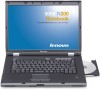
Lenovo 3000 N200 Hardware Maintenance Manual May 2007 This manual supports: Lenovo 3000 N200 (MT 0687) - Lenovo 0769AK8 | Hardware Maintenance Manual - Page 2
- Lenovo 0769AK8 | Hardware Maintenance Manual - Page 3
Lenovo 3000 N200 Hardware Maintenance Manual - Lenovo 0769AK8 | Hardware Maintenance Manual - Page 4
this information and the product it supports, be sure to read the general information under "Notices" on page 97. First Edition (May 2007) © Copyright Lenovo 2007. All rights reserved. U.S. GOVERNMENT USERS - RESTRICTED RIGHTS: Our products and/or services are provided with RESTRICTED RIGHTS. Use - Lenovo 0769AK8 | Hardware Maintenance Manual - Page 5
17 Related service information 19 Service Web site 19 Restoring the factory contents by using Product Recovery discs 19 Passwords 20 Power management 22 Checkout guide 24 Testing the computer 24 Detecting system information with PC-Doctor . . 26 Power system checkout 26 Lenovo 3000 N200 29 - Lenovo 0769AK8 | Hardware Maintenance Manual - Page 6
iv MT 0687 - Lenovo 0769AK8 | Hardware Maintenance Manual - Page 7
information for Lenovo 3000 N200 (MT 0687). Use this manual along with the advanced diagnostic tests to troubleshoot problems. The manual is divided into sections as follows: v The common sections provide general information, guidelines, and safety information required in servicing computers. v The - Lenovo 0769AK8 | Hardware Maintenance Manual - Page 8
service information v If you are instructed to replace a FRU but the replacement does not correct the problem, reinstall the original FRU before you continue. v Some computers have both a processor board and a system board. If you are instructed are used to support CMV products. These sources are PC Entitlement Warehouse - Lenovo 0769AK8 | Hardware Maintenance Manual - Page 9
v eSupport can be accessed at the following Web site: http://www.lenovo.com/ support v To view the key commodities, click on PARTS INFORMATION, then PARTS by Category" select SERVICE PARTS. Under "Parts Information by Date" select SYSTEM SERVICE PARTS. The list of service parts by description, - Lenovo 0769AK8 | Hardware Maintenance Manual - Page 10
Important service information Important information about replacing RoHS compliant FRUs RoHS, The also be RoHS compliant. Lenovo plans to transition to RoHS compliance well before the implementation date and expects its suppliers to be ready to support Lenovo's requirements and schedule. Products - Lenovo 0769AK8 | Hardware Maintenance Manual - Page 11
and write Not compatible Safety notices: multilingual translations In this manual, safety notices appear in English with a page number , French, German, Hebrew, Italian, and Spanish. Safety notice 1 Before the computer is powered on after FRU replacement, make sure all screws, springs, and other - Lenovo 0769AK8 | Hardware Maintenance Manual - Page 12
Safety notices Safety notice 2 DANGER Some standby batteries contain a small amount of nickel and cadmium. Do not disassemble a standby battery, recharge it, throw it into fire or water, or short-circuit it. Dispose of the battery as required by local ordinances or regulations. Use only the battery - Lenovo 0769AK8 | Hardware Maintenance Manual - Page 13
Safety notice 3 DANGER Safety notices The battery pack contains small amounts of nickel. Do not disassemble it, throw it into fire or water, or short-circuit it. Dispose of the battery pack as required by local ordinances or regulations. Use only the battery in the appropriate parts listing when - Lenovo 0769AK8 | Hardware Maintenance Manual - Page 14
Safety notices Safety notice 4 DANGER The lithium battery can cause a fire, an explosion, or a severe burn. Do not recharge it, remove its polarized connector, disassemble it, heat it above 100°C (212°F), incinerate it, or expose its cell contents to water. Dispose of the battery as required by - Lenovo 0769AK8 | Hardware Maintenance Manual - Page 15
Entsorgung die örtlichen Bestimmungen für Sondermüll beachten. Der LCD-Bildschirm besteht aus Glas und kann zerbrechen, wenn er unsachgemäß behandelt wird oder der Computer auf den Boden fällt. Wenn der Bildschirm beschädigt ist und die darin befindliche Flüssigkeit in Kontakt mit Haut und Augen ger - Lenovo 0769AK8 | Hardware Maintenance Manual - Page 16
quemar material combustible o provocar quemaduras en el personal. Safety notice 8 DANGER Before removing any FRU, power off the computer, unplug all power cords from electrical outlets, remove the battery pack, and then disconnect any interconnecting cables. Avant de retirer une unité remplaçable en - Lenovo 0769AK8 | Hardware Maintenance Manual - Page 17
Safety information Safety information The following section presents safety information with which you need to be familiar before you service a Lenovo 3000 computer. General safety Follow these rules to ensure general safety: v Observe good housekeeping in the area of the machines during and after - Lenovo 0769AK8 | Hardware Maintenance Manual - Page 18
the room emergency power-off (EPO) switch, disconnecting switch, or electrical outlet. If an electrical accident occurs, you can then operate the switch or unplug safety precautions when you work with very high voltages; Instructions for these precautions are in the safety sections of maintenance - Lenovo 0769AK8 | Hardware Maintenance Manual - Page 19
service personnel from injury. This guide Lenovo 3000 features or options not covered by this inspection guide . If any unsafe conditions are present, you must determine how serious the apparent hazard could be and whether you can continue without first correcting the problem the computer. - Lenovo 0769AK8 | Hardware Maintenance Manual - Page 20
, to provide protection that meets the specific service requirement. Note The use of a grounding system ac plug on ac-operated computers. Grounding requirements Electrical grounding of the computer is required for operator safety and correct system function. Proper grounding of the electrical outlet - Lenovo 0769AK8 | Hardware Maintenance Manual - Page 21
statement Laser compliance statement Some models of Lenovo 3000 computer are equipped from the factory with an certified in the U.S. to conform to the requirements of the Department of Health and Human Services 21 Code of Federal Regulations (DHHS 21 CFR) Subchapter J for Class 1 laser products - Lenovo 0769AK8 | Hardware Maintenance Manual - Page 22
Laser compliance statement A CD-ROM drive, a DVD-ROM drive, or any other storage device installed may contain an embedded Class 3A or Class 3B laser diode. Note the following: DANGER Emits visible and invisible laser radiation when open. Do not stare into the beam, do not view directly with optical - Lenovo 0769AK8 | Hardware Maintenance Manual - Page 23
any Lenovo 3000 model that has the PC-Doctor® for DOS diagnostics program. Some descriptions might not apply to your particular computer. Read this first Before you go to the checkout guide, be sure to read this section. Important notes v Only certified trained personnel should service the computer - Lenovo 0769AK8 | Hardware Maintenance Manual - Page 24
computer password (making the computer unusable) v Sticky keys caused by spilling a liquid onto the keyboard v Use of an incorrect ac adapter on laptop products The following symptoms might indicate damage caused by nonwarranted activities: v Missing parts might be a symptom of unauthorized service - Lenovo 0769AK8 | Hardware Maintenance Manual - Page 25
Service Web site When the latest maintenance diskette and the system program service diskette become available, they will be posted on http://www.lenovo files and click Next. e. A warning opens not to turn off the computer during the recovery process. Click OK. 4. When the Product Recovery window - Lenovo 0769AK8 | Hardware Maintenance Manual - Page 26
the instructions on the screen to complete the Windows setup. Passwords As many as three passwords may be needed for any Lenovo 3000 computer: disk drive. If no master HDP is available, neither Lenovo nor Lenovo authorized servicers provide any services to reset either the user or the master HDP, or - Lenovo 0769AK8 | Hardware Maintenance Manual - Page 27
the backup battery and the battery pack. (B) If an SVP has been set and is known by the servicer: 1. Turn on the computer; then, while the initial screen is displayed, press the Lenovo CareSM button. The Rescue and Recovery screen opens. 2. Click Access BIOS. The System Restart Required window is - Lenovo 0769AK8 | Hardware Maintenance Manual - Page 28
Related service information 10. Select Yes in the Setup Configuration window. Both user HDP and master HDP will have been removed. Power management Note: Power management modes are not supported for APM operating system. To reduce power consumption, the computer has three power management modes: - Lenovo 0769AK8 | Hardware Maintenance Manual - Page 29
Related service information v Press the Fn+F12 keys. v If you are using the ACPI operating system and have defined one of the following actions as the event that causes the system to go into hibernation mode, perform that action. - Closing the lid. - Pressing the power button. Also, the computer - Lenovo 0769AK8 | Hardware Maintenance Manual - Page 30
Use the following procedures as a guide in identifying and correcting problems with the Lenovo 3000 computer. Note: The diagnostic tests are intended to test only Lenovo 3000 products. The use of non-Lenovo 3000 products, prototype cards, or modified options can lead to false indications of errors - Lenovo 0769AK8 | Hardware Maintenance Manual - Page 31
. v Video Adapter test supports only the LCD display on the Lenovo 3000 computer. If you have an external monitor attached to your computer, detach it before running PC-Doctor for DOS. 4. Run the applicable function test. 5. Follow the instructions on the screen. If there is a problem, PC-Doctor - Lenovo 0769AK8 | Hardware Maintenance Manual - Page 32
SYSTEM HEALTH v SYSTEM AND DEVICE TESTS v LENOVO TROUBLESHOOTING v CENTER v SYSTEM REPORTS v UPDATES AND SUPPORT Power system checkout To verify a symptom, do the following: 1. Turn off the computer. 2. Remove the battery pack. 3. Connect the ac adapter. 4. Check that power is supplied when you - Lenovo 0769AK8 | Hardware Maintenance Manual - Page 33
the ac adapter cable from the computer. 2. Measure the output voltage at the plug of the ac adapter cable. See the following figure: 3 2 1 (20V) Pin Voltage (V dc) 1 +20 2 0 3 Ground Note: Output voltage of pin no.2 of the ac adapter may be different from the one you are servicing. 3. If - Lenovo 0769AK8 | Hardware Maintenance Manual - Page 34
Checkout guide Note: If the battery pack becomes hot, it may not be able to charge. Remove it from the computer and leave it at room temperature for a while. After it cools down, reinstall and recharge it. To check the battery pack, do the following: 1. Power off the computer. 2. Remove the battery - Lenovo 0769AK8 | Hardware Maintenance Manual - Page 35
Lenovo 3000 N200 Product overview 30 Specifications 30 Status indicators 32 FRU tests 33 Fn key combinations 34 Symptom-to-FRU index 35 Numeric error codes 35 Error messages 37 No-beep symptoms 38 LCD-related symptoms 39 Intermittent problems 40 Undetermined problems 40 FRU replacement - Lenovo 0769AK8 | Hardware Maintenance Manual - Page 36
table lists the specifications of the Lenovo 3000 N200: Feature Processor Bus architecture Graphic memory GB, 5400 rpm, 9.5 mm high, SATA interface 160 GB, 5400 rpm, 9.5 mm high, SATA interface Supported hard disk drives are depend on the model. · DVD/CD‐RW combo drive, 12.7 mm high · DVD - Lenovo 0769AK8 | Hardware Maintenance Manual - Page 37
Ethernet (on the system board) Mini PCI adapter ExpressCard slot Bluetooth wireless (some models) Modem Touch pad Battery AC adapter Preinstalled operating system Description v 5-1 Digital Home Basic (32 bit) v Windows Vista Business (32 bit) v Windows Vista Ultimate (32 bit) Lenovo 3000 N200 31 - Lenovo 0769AK8 | Hardware Maintenance Manual - Page 38
: Data is being read from or written to the hard disk drive. When this indicator is on, do not put the computer into sleep (standby) mode or turn off the computer. Note: Do not move the system while the green drive-in-use light is on. Sudden physical shock could cause drive - Lenovo 0769AK8 | Hardware Maintenance Manual - Page 39
capacity. Green: The computer is in sleep (standby) mode. Blinking green: The computer is entering sleep (standby 1. Diagnostics --> Video Adapter 2. Interactive Tests --> of them and run Diagnostics --> Memory Test-Quick. 2. If the problem does not recur, return the DIMM to its place, remove the - Lenovo 0769AK8 | Hardware Maintenance Manual - Page 40
each combination of Fn with a function key. Key combination Description Fn+F1 Volume down. Fn+F2 Volume up. Fn+F3 Reserved. Fn+F4 Put the computer in sleep (standby) mode. To return to normal operation, press the Fn key only, without pressing a function key. Fn+F5 Enable or disable the - Lenovo 0769AK8 | Hardware Maintenance Manual - Page 41
descriptions of symptoms. If the symptom is not described there, go to "Intermittent problems" on page 40. Note For a device not supported by diagnostic codes in the Lenovo 3000 notebook computers, see the manual for that device. Numeric error codes Symptom or error 0200 Failure Fixed Disk 021x - Lenovo 0769AK8 | Hardware Maintenance Manual - Page 42
and run BIOS Setup Utility to reset the time and date. 3. System board. 1. Charge the backup battery for more than 8 hours by connecting the ac adapter. 2. Replace the backup battery and run BIOS Setup Utility to reset the time and date. 3. System board. 1. Load "Setup Default" in BIOS Setup Utility - Lenovo 0769AK8 | Hardware Maintenance Manual - Page 43
Thermal sensing error. Authentication of system services failed. Press to resume or action, in sequence DIMM. Make sure to use supported memory. 1. Load "Setup Defaults" in the BIOS configuration to what it was before the computer entered hibernation mode. 2. If memory size Lenovo 3000 N200 37 - Lenovo 0769AK8 | Hardware Maintenance Manual - Page 44
Symptom-to-FRU index No-beep symptoms Symptom or error FRU or action, in sequence No beep, power-on indicator on, LCD blank, 1. Make sure that every connector is and no POST. connected tightly and correctly. 2. DIMM. 3. System board. No beep, power-on indicator on, and LCD blank during POST. - Lenovo 0769AK8 | Hardware Maintenance Manual - Page 45
computer contains many thin-film transistors (TFTs). The presence of a small number of dots that are missing, discolored, or always lighted is characteristic of TFT LCD technology, but excessive pixel problems all LCD connectors. 3. LCD assembly. 4. System board. LCD assembly. Lenovo 3000 N200 39 - Lenovo 0769AK8 | Hardware Maintenance Manual - Page 46
not identify the adapter or device that has failed, if wrong devices are installed, or if the system simply is not operating, follow these procedures to isolate the failing FRU (do not isolate FRUs that have no defects). Verify that all attached devices are supported by the computer. Verify that the - Lenovo 0769AK8 | Hardware Maintenance Manual - Page 47
notices Loose screws can cause a reliability problem. In the Lenovo 3000 computer, this problem is addressed with special nylon-coated surface of the logic card: 180 degrees more (Cross-section) v Torque driver If you have a torque driver, refer to the "Torque" column for each step. v Make sure - Lenovo 0769AK8 | Hardware Maintenance Manual - Page 48
doing the following: 1. Install the CE Utility Diskette for Lenovo 3000 notebooks and restart the computer. 2. From the main menu, select 1. Set System Identification. 3. Select 1. Add S/N data from EEPROM. Follow the instructions on the screen. Retaining the UUID The Universally Unique Identifier - Lenovo 0769AK8 | Hardware Maintenance Manual - Page 49
to it. 1. Insert the CE Utility Diskette for Lenovo 3000 notebooks, and restart the computer. 2. From the main menu, select 6. Set ECA Information. 3. To write ECA information, select 1. Write ECA/rework number from EEPROM, and follow the instruction. 4. To write box build date, select 4. Write box - Lenovo 0769AK8 | Hardware Maintenance Manual - Page 50
to service any computer unless you have been trained and certified. An untrained person runs the risk of damaging parts. 2. Before replacing any FRU, review " Before removing any FRU, turn off the computer, unplug all power cords from electrical outlets, remove the battery pack, and then disconnect - Lenovo 0769AK8 | Hardware Maintenance Manual - Page 51
1010 Battery pack DANGER Removing and replacing a FRU Use only the battery specified in the parts list for your computer. Any other battery could ignite or explode. Unlock the battery release lever 1 and holding the battery release lever in the unlocked position 2 , remove the battery - Lenovo 0769AK8 | Hardware Maintenance Manual - Page 52
Removing and replacing a FRU 1020 Hard disk drive slot cover For access, remove this FRU: v "1010 Battery pack" on page 45 Note: Loosen the screws 1 , but do not remove them. 2 1 1030 Hard disk drive For access, remove these FRUs in order: v "1010 Battery pack" on page 45 v "1020 Hard disk drive - Lenovo 0769AK8 | Hardware Maintenance Manual - Page 53
Removing and replacing a FRU 1040 DIMM slot cover For access, remove this FRU: v "1010 Battery pack" on page 45 Note: Loosen the screws 1 , but do not remove them. 1 2 Lenovo 3000 N200 47 - Lenovo 0769AK8 | Hardware Maintenance Manual - Page 54
Removing and replacing a FRU 1050 DIMM For access, remove these FRUs in order: v "1010 Battery pack" on page 45 v "1040 DIMM slot cover" on page 47 2 1 1 When installing: Insert the notched end of the DIMM into the socket. Press the DIMM firmly, and pivot it until it snaps into the place. Make sure - Lenovo 0769AK8 | Hardware Maintenance Manual - Page 55
the arrow. When installing: Plug the gray cable into the jack labeled MAIN on the card, and the black cable into the jack labeled AUX. Lenovo 3000 N200 49 - Lenovo 0769AK8 | Hardware Maintenance Manual - Page 56
Removing and replacing a FRU 1070 PCI Express Mini Card for 802.11 a/b/g/n wireless LAN For access, remove these FRUs in order: v "1010 Battery pack" on page 45 v "1040 DIMM slot cover" on page 47 1 2 1 3 Step 1 Screw (quantity) M2 × 3 mm, pan-head, nylon-coated (2) Color Black Torque 0.245 - Lenovo 0769AK8 | Hardware Maintenance Manual - Page 57
1080 Optical drive For access, remove these FRUs in order: v "1010 Battery pack" on page 45 v "1040 DIMM slot cover" on page 47 Removing and replacing a FRU 1 2 Step 1 Screw (quantity) M2.5 × 6 mm, pan-head, nylon-coated (1) 3 Color Torque Dark silver 0.392 Nm (4 kgfcm) Lenovo 3000 N200 51 - Lenovo 0769AK8 | Hardware Maintenance Manual - Page 58
Removing and replacing a FRU 1090 Heat sink assembly slot cover For access, remove this FRU: v "1010 Battery pack" on page 45 Note: Loosen the screws 1 , but do not remove them. 1 2 52 MT 0687 - Lenovo 0769AK8 | Hardware Maintenance Manual - Page 59
Note: Loosen the screws 1 , but do not remove them. 2 2 1 Step 2 Screw (quantity) M2 × 3 mm, pan-head, nylon-coated (2) (continued) Color Black Torque 0.245 Nm (2.5 kgfcm) Lenovo 3000 N200 53 - Lenovo 0769AK8 | Hardware Maintenance Manual - Page 60
Removing and replacing a FRU 3 4 When installing: Make sure that the fan connector is attached firmly. When installing: Before you attach a new heat sink assembly to the computer, peel off the covering film of thermal grease. Then attach the heat sink assembly to the computer. 54 MT 0687 - Lenovo 0769AK8 | Hardware Maintenance Manual - Page 61
cover" on page 52 v "1100 Heat sink assembly" on page 53 Attention: CPU is extremely sensitive. When you service the CPU, avoid any kind of rough handling. Rotate the head of the screw in the direction shown by arrow the screw in the direction shown by arrow b to secure the CPU. Lenovo 3000 N200 55 - Lenovo 0769AK8 | Hardware Maintenance Manual - Page 62
Removing and replacing a FRU 1120 Middle cover and function board For access, remove this FRU: v "1010 Battery pack" on page 45 Note: The function board is attached to the middle cover. 1 1 Step 1 Screw (quantity) M2.5 × 3 mm, wafer-head, nylon-coated (2) Color Silver Torque 0.392 Nm (4 kgfcm) - Lenovo 0769AK8 | Hardware Maintenance Manual - Page 63
attached firmly. To remove the function board, do as follows: 1 2 1 Step 2 Screw (quantity) M2 × 3 mm, pan-head, nylon-coated (2) Color Black Torque 0.392 Nm (4 kgfcm) Lenovo 3000 N200 57 - Lenovo 0769AK8 | Hardware Maintenance Manual - Page 64
Removing and replacing a FRU 1130 Keyboard For access, remove these FRUs in order: v "1010 Battery pack" on page 45 v "1120 Middle cover and function board" on page 56 1 Step 1 Screw (quantity) M2 x 3 mm, pan-head, nylon-coated (1) (continued) Color Black Torque 0.245 Nm (2.5 kgfcm) 58 MT 0687 - Lenovo 0769AK8 | Hardware Maintenance Manual - Page 65
sure that the keyboard connector is attached firmly. Then lock the connector. 2. Make sure that the front side of the keyboard is under the frame. Lenovo 3000 N200 59 - Lenovo 0769AK8 | Hardware Maintenance Manual - Page 66
Removing and replacing a FRU 1140 Keyboard bezel and fingerprint reader card For access, remove these FRUs in order: v "1010 Battery pack" on page 45 v "1020 Hard disk drive slot cover" on page 46 v "1040 DIMM slot cover" on page 47 v "1060 PCI Express Mini Card for 802.11 a/b/g wireless LAN" on - Lenovo 0769AK8 | Hardware Maintenance Manual - Page 67
3 , and release them from the cable guides of the frame 4 . 4 4 4 3 When installing: Route the antenna cables along the cable guides. When you route the cables, do not tense them. To do so, the cables may get damaged by the cable guides of the frame, and may cause a broken wire. Lenovo 3000 N200 61 - Lenovo 0769AK8 | Hardware Maintenance Manual - Page 68
Removing and replacing a FRU 7 6 5 Step 7 Screw (quantity) M2.5 × 6 mm, pan-head, nylon-coated (1) Color Torque Dark silver 0.392 Nm (4 kgfcm) When installing: Make sure that the connectors are attached firmly. (continued) 62 MT 0687 8 9 - Lenovo 0769AK8 | Hardware Maintenance Manual - Page 69
card in the direction shown by the arrow 3 , and then remove the fingerprint reader card 4 . 3 4 When installing: Make sure that the connector is attached firmly. Lenovo 3000 N200 63 - Lenovo 0769AK8 | Hardware Maintenance Manual - Page 70
Removing and replacing a FRU 1150 Backup battery DANGER Use only the battery specified in the parts list for your computer. Any other battery could ignite or explode. For access, remove these FRUs in order: v "1010 Battery pack" on page 45 v "1020 Hard disk drive slot - Lenovo 0769AK8 | Hardware Maintenance Manual - Page 71
1 1 3 2 Step 1 Screw (quantity) M2 × 3 mm, pan-head, nylon-coated (2) Color Black Torque 0.245 Nm (2.5 kgfcm) When installing: Make sure that the connector is attached firmly. Lenovo 3000 N200 65 - Lenovo 0769AK8 | Hardware Maintenance Manual - Page 72
Removing and replacing a FRU 1170 Bluetooth daughter card (BDC) For access, remove these FRUs in order: v "1010 Battery pack" on page 45 v "1020 Hard disk drive slot cover" on page 46 v "1060 PCI Express Mini Card for 802.11 a/b/g wireless LAN" on page 49 v "1070 PCI Express Mini Card for 802.11 - Lenovo 0769AK8 | Hardware Maintenance Manual - Page 73
(quantity) M2.5 × 9 mm, pan-head, nylon-coated (5) Color Torque Dark silver 0.392 Nm (4 kgfcm) 2 When installing: Make sure that the connector is attached firmly. (continued) Lenovo 3000 N200 67 - Lenovo 0769AK8 | Hardware Maintenance Manual - Page 74
Removing and replacing a FRU 3 4 3 4 Step 3 Screw (quantity) M2.5 × 9 mm, pan-head, nylon-coated (2) Color Torque Dark silver 0.392 Nm (4 kgfcm) 68 MT 0687 - Lenovo 0769AK8 | Hardware Maintenance Manual - Page 75
(quantity) M2.5 × 6 mm, pan-head, nylon-coated (3) Color Torque Dark silver 0.392 Nm (4 kgfcm) When installing: Make sure that the connector is attached firmly. (continued) Lenovo 3000 N200 69 - Lenovo 0769AK8 | Hardware Maintenance Manual - Page 76
Removing and replacing a FRU To remove the 5-1 Digital Media Reader board, do as follows: 1 1 2 Step 1 Screw (quantity) M2 × 3 mm, pan-head, nylon-coated (2) Color Black Torque 0.245 Nm (2.5 kgfcm) When installing: Make sure that the connector is attached firmly. (continued) 70 MT 0687 - Lenovo 0769AK8 | Hardware Maintenance Manual - Page 77
over the system board, and disconnect the ExpressCard slot assembly. 2 When installing: Make sure that the connector is attached firmly, and then fasten the screws. Lenovo 3000 N200 71 - Lenovo 0769AK8 | Hardware Maintenance Manual - Page 78
Removing and replacing a FRU 2010 LCD front bezel For access, remove this FRU: v "1010 Battery pack" on page 45 1 1 1 1 Step 1 Screw cap Screw (quantity) M2.5 × 5 mm, pan-head, nylon-coated (4) Color Silver Torque 0.392 Nm (4 kgfcm) In step 2 , while sliding the LCD latch lever in the - Lenovo 0769AK8 | Hardware Maintenance Manual - Page 79
1 4 1 2 3 Step 1 Screw (quantity) M2.5 × 5 mm, pan-head, nylon-coated (2) Color Silver Torque 0.392 Nm (4 kgfcm) When installing: Make sure that connectors 3 and 4 are attached firmly. Lenovo 3000 N200 73 - Lenovo 0769AK8 | Hardware Maintenance Manual - Page 80
Removing and replacing a FRU 2030 LCD panel, LCD cable, and hinges For access, remove these FRUs in order: v "1010 Battery pack" on page 45 v "1020 Hard disk drive slot cover" on page 46 v "1060 PCI Express Mini Card for 802.11 a/b/g wireless LAN" on page 49 v "1070 PCI Express Mini Card for 802.11 - Lenovo 0769AK8 | Hardware Maintenance Manual - Page 81
Removing and replacing a FRU Remove the hinges ( a ) from the LCD panel. a 5 4 4 a5 Step 4 4 4 Screw (quantity) M2 × 2.5 mm, pan-head, nylon-coated (8) Color Silver Remove the LCD cable assembly ( b ) from the LCD panel. Torque 0.245 Nm (2.5 kgfcm) 6 7 b Lenovo 3000 N200 75 - Lenovo 0769AK8 | Hardware Maintenance Manual - Page 82
Removing and replacing a FRU 2040 Camera and LCD rear cover assembly For access, remove these FRUs in order: v "1010 Battery pack" on page 45 v "1020 Hard disk drive slot cover" on page 46 v "1060 PCI Express Mini Card for 802.11 a/b/g wireless LAN" on page 49 v "1070 PCI Express Mini Card for 802. - Lenovo 0769AK8 | Hardware Maintenance Manual - Page 83
(quantity) M2 × 3 mm, pan-head, nylon-coated (2) Color Silver Torque 0.245 Nm (2.5 kgfcm) Cable routing: Route the cables as shown in the following figure. (continued) Lenovo 3000 N200 77 - Lenovo 0769AK8 | Hardware Maintenance Manual - Page 84
Removing and replacing a FRU For the antennas with three cables 1 1 2 22 Step 1 Screw (quantity) M2 × 3 mm, pan-head, nylon-coated (2) Color Silver Torque 0.245 Nm (2.5 kgfcm) Cable routing: Route the cables as shown in the following figure. 78 MT 0687 - Lenovo 0769AK8 | Hardware Maintenance Manual - Page 85
Locations Locations Front view 1 Lenovo Care button 2 Volume control buttons 3 Keyboard 4 Fingerprint reader (for some models) 5 Built-in stereo speaker (right) 6 . 15 Power switch 16 Integrated camera (for some models) 16 15 1 2 3 4 5 14 13 12 11 10 6 7 8 9 Lenovo 3000 N200 79 - Lenovo 0769AK8 | Hardware Maintenance Manual - Page 86
Locations Rear view 1 USB connectors 2 S-Video connector 3 External monitor connector 4 AC power connector 5 RJ-45 (Ethernet) connector 6 USB connectors 7 IEEE1394 connector 8 Microphone jack 9 Stereo headphone jack 10 ExpressCard slot 10 9 8 7 6 5 Bottom view 1 Heat sink - Lenovo 0769AK8 | Hardware Maintenance Manual - Page 87
Internal CRU. Lenovo 3000 computers contain the following types of the external CRUs: External CRUs (pluggable) These CRUs unplug from the computer. Examples of these types of CRUs include an ac adapter, an external compliant FRU. v FRUs marked with OP are available as options. Lenovo 3000 N200 81 - Lenovo 0769AK8 | Hardware Maintenance Manual - Page 88
Parts list Overall 1 2 3 4 5 6 7 8 b 23 9 22 10 a 21 11 20 12 19 13 14 18 15 17 16 82 MT 0687 - Lenovo 0769AK8 | Hardware Maintenance Manual - Page 89
41R7515 System board assembly, 14W discrete 256 v 0687-32x, 4Mx, 4Nx, 4Vx, 4Wx, 4Xx, 4Yx, 67x, 68x, 72x, 73x 41R7516 RoHS CRU ID ID R N R N R N R N R N R N R N R N R N R N (continued) Lenovo 3000 N200 83 - Lenovo 0769AK8 | Hardware Maintenance Manual - Page 90
Parts list No. FRU FRU no. RoHS CRU ID ID 10 CPU assembly, Intel Celeron M processor 540 (1.86 GHz) 41R7621 R N v 0687-29x, 46x, 47x, 4Gx, 4Hx, 4Qx, 4Ux CPU assembly, Intel Core 2 Duo processor T7100 (1.83 42W7654 R N GHz) v 0687-27x, 28x, 2Ax, 2Bx, 48x, 49x, 4Ax, 4Bx, 4Cx, 4Dx, 4Jx, 4Kx, - Lenovo 0769AK8 | Hardware Maintenance Manual - Page 91
** xxA, xxB, xxG, xxH, xxK, xxL, xxM, xxP, xxQ, xxR, 42T0823 R ** xxS, xxY Lenovo 11a/b/g/n Wireless LAN Mini-PCI Express Adapter v 0687-48x, 49x, 67x, 68x, 69x, 6Ax, 6Bx, 6Cx, 6Dx, 6Ex, 72x, 73x xxA, xxB , xxU, xxV, 42T0865 R ** xxQ, xxY xxG 42T0867 R ** (continued) Lenovo 3000 N200 85 - Lenovo 0769AK8 | Hardware Maintenance Manual - Page 92
Parts list No. FRU FRU no. RoHS CRU ID ID 18 512-MB DDR2-667 SDRAM SO-DIMM (PC2-5300) card 40Y8402 R ** OP v 0687-27x, 28x, 29x, 2Ax, 46x, 47x, 48x, 49x, 4Ax, 4Bx, 4Cx, 4Dx, 4Gx, 4Hx, 4Jx, 4Kx, 4Px, 4Qx, 4Rx, 4Sx, 4Tx, 4Ux, 6Ax, 6Bx, 6Cx, 6Dx 1-GB DDR2-667 SDRAM SO-DIMM (PC2-5300) card - Lenovo 0769AK8 | Hardware Maintenance Manual - Page 93
LCD FRUs 8 7 14.1-in. WXGA TFT No. FRU 1 LCD front bezel (continued) Parts list 1 2 3 4 5 6 FRU no. 41R7520 RoHS CRU ID ID R N Lenovo 3000 N200 87 - Lenovo 0769AK8 | Hardware Maintenance Manual - Page 94
Parts list No. FRU FRU no. RoHS CRU ID ID 2 LCD panel, 14.1-in. WXGA anti-glare v 0687-2Ax, 48x CMO 42T0377 R N LPL 42T0381 R N Samsung 13N7154 R N LCD panel, 14.1-in. WXGA glare v 0687-27x, 28x, 29x, 2Bx, 32x, 46x, 47x, 49x, 4Ax, 4Bx, 4Cx, 4Dx, 4Ex, 4Gx, 4Hx, 4Jx, 4Kx, 4Lx, 4Mx, 4Nx, - Lenovo 0769AK8 | Hardware Maintenance Manual - Page 95
42T3403 42T3433 42T3410 42T3405 42T3404 42T3408 42T3406 42T3425 42T3420 42T3424 - 42T3413 42T3428 42T3430 42T3411 42T3421 42T3417 42T3434 42T3419 42T3427 42T3426 42T3414 42T3431 42T3416 42T3432 42T3422 Lenovo 3000 N200 89 - Lenovo 0769AK8 | Hardware Maintenance Manual - Page 96
Parts list Recovery discs Windows XP Professional CDs Windows XP Professional is preinstalled as the operating system in the following ·models: 0687‐2Cx Language Arabic Chinese, Simplified Chinese, Traditional Chinese, Traditional (Hong Kong S.A.R.) Czech Danish Dutch English, U.K. with disabled - Lenovo 0769AK8 | Hardware Maintenance Manual - Page 97
Parts list Recovery discs Windows Vista Home Premium (32 bit) DVDs Windows Vista Home Premium is preinstalled as the operating system in the following models: v 0687-27x, 2Bx, 47x, 48x, 4Ex, 4Lx, 4Rx, 4Sx, 4Zx, 6Ex Language Bulgarian Chinese, Simplified Chinese, Traditional Chinese, Traditional ( - Lenovo 0769AK8 | Hardware Maintenance Manual - Page 98
44Y0081 44Y0066 44Y0065 44Y0078 44Y0070 44Y0071 44Y0087 44Y0072 44Y0088 44Y0073 44Y0074 44Y0080 44Y0082 44Y0086 44Y0068 44Y0083 44Y0067 44Y0089 44Y0075 44Y0084 44Y0090 RoHS CRU ID ID R * Lenovo 3000 N200 91 - Lenovo 0769AK8 | Hardware Maintenance Manual - Page 99
Parts list Windows Vista Business (32 bit) DVDs Windows Vista Business is preinstalled as the operating system in the following models: v 0687-28x, 32x, 49x, 4Dx, 73x, 4Hx, 4Kx, 4Nx, 4Tx, 4Ux, 4Wx, 4Yx, 52x, 68x, 69x, 6Dx Language Bulgarian Chinese, Simplified Chinese, Traditional Chinese, - Lenovo 0769AK8 | Hardware Maintenance Manual - Page 100
44Y0102 44Y0106 44Y0092 44Y0091 44Y0103 44Y0096 44Y0097 44Y0112 44Y0113 44Y0098 44Y0099 44Y0105 44Y0107 44Y0111 44Y0094 44Y0108 44Y0093 44Y0100 44Y0114 44Y0109 44Y0115 RoHS CRU ID ID R * Lenovo 3000 N200 93 - Lenovo 0769AK8 | Hardware Maintenance Manual - Page 101
CDs Language English, U.S. French Japanese Portuguese, Brazilian Spanish P/N 41X0440 41X0443 41X0608 41X0449 41X0446 RoHS CRU ID ID R * AC adapters FRU P/N RoHS ID 2-pin (90 W, 20 V) adapter (models xxE, xxF, xxJ, xxL, xxP, xxS, xxU, xxY) OP CRU ID ASTEC 42T5000 R * Lite-On 93P5026 - Lenovo 0769AK8 | Hardware Maintenance Manual - Page 102
USB parallel test cable 05K2580 Screwdriver kit 95F3598 Mini PC tool set 00P7033 1/4" drive spinner handle 1650840 1/4" Sq. to 1/4" hex torx adapter 93F2838 TR7-TR-10 tamper resistant torx bits 00P6967 Removal tool antenna RF connector 08K7159 PCI-Express/USB wrap card 27K9813 CE - Lenovo 0769AK8 | Hardware Maintenance Manual - Page 103
Parts list Power cords A Lenovo 3000 power cord for a specific country or region is usually available only in that country or region: For 2-pin power cords: Region Argentina Brazil Canada, U.S. - Lenovo 0769AK8 | Hardware Maintenance Manual - Page 104
and verify the operation of any other product, program, or service. Lenovo may have patents or pending patent applications covering subject matter are not intended for use in implantation or other life support applications where malfunction may result in injury or death to Lenovo 3000 N200 97 - Lenovo 0769AK8 | Hardware Maintenance Manual - Page 105
environment. The following terms are trademarks of Lenovo in the United States, other countries or both: Lenovo Lenovo Care Rescue and Recovery The following terms are ® Intel® Core™ 2 Duo Celeron® Other company, product, or service names may be the trademarks or service marks of others. 98 MT 0687 - Lenovo 0769AK8 | Hardware Maintenance Manual - Page 106
Trademarks Lenovo 3000 N200 99 - Lenovo 0769AK8 | Hardware Maintenance Manual - Page 107
Part Number: 42X3552 (1P) P/N: 42X3552
-
 1
1 -
 2
2 -
 3
3 -
 4
4 -
 5
5 -
 6
6 -
 7
7 -
8
-
9
-
10
-
11
-
12
-
13
-
14
-
15
-
16
-
17
-
18
-
19
-
20
-
21
-
22
-
23
-
24
-
25
-
26
-
27
-
28
-
29
-
30
-
31
-
32
-
33
-
34
-
35
-
36
-
37
-
38
-
39
-
40
-
41
-
42
-
43
-
44
-
45
-
46
-
47
-
48
-
49
-
50
-
51
-
52
-
53
-
54
-
55
-
56
-
57
-
58
-
59
-
60
-
61
-
62
-
63
-
64
-
65
-
66
-
67
-
68
-
69
-
70
-
71
-
72
-
73
-
74
-
75
-
76
-
77
-
78
-
79
-
80
-
81
-
82
-
83
-
84
-
85
-
86
-
87
-
88
-
89
-
90
-
91
-
92
-
93
-
94
-
95
-
96
-
97
-
98
-
99
-
100
-
101
-
102
-
103
-
104
-
105
-
106
-
107
 |
 |

Lenovo
3000
N200
Hardware
Maintenance
Manual
May
2007
This
manual
supports:
Lenovo
3000
N200
(MT
0687)