Lenovo B300 Lenovo IdeaCentre B300 Hardware Maintenance Manual V2.1
Lenovo B300 Manual
 |
View all Lenovo B300 manuals
Add to My Manuals
Save this manual to your list of manuals |
Lenovo B300 manual content summary:
- Lenovo B300 | Lenovo IdeaCentre B300 Hardware Maintenance Manual V2.1 - Page 1
safety...4 Electrical safety...5 Safety inspection guide 7 Handling electrostatic discharge-sensitive devices 8 Grounding requirements 8 Safety notices...9 Chapter 3. General information 12 Specifications...12 Chapter 4. General Checkout 13 Problem determination tips 14 Chapter 5. Using - Lenovo B300 | Lenovo IdeaCentre B300 Hardware Maintenance Manual V2.1 - Page 2
Replacing the motherboard 50 Removing the shell 51 Replacing the camera 52 Replacing the touch module 53 Replacing the LED panel 54 Replacing the keyboard 57 Replacing the mouse 58 Replacing the power cord or power adapter 59 Chapter 9. Additional Service Information 60 Power management 60 - Lenovo B300 | Lenovo IdeaCentre B300 Hardware Maintenance Manual V2.1 - Page 3
B3 computers listed on the cover. It is intended only for trained servicers who are familiar with Lenovo computer products. Before servicing a Lenovo product, be sure to read the Safety Information. The description of the TV card in this manual is only used for the machines which have the TV - Lenovo B300 | Lenovo IdeaCentre B300 Hardware Maintenance Manual V2.1 - Page 4
, if the parts are compliant, the replacement parts must also be compliant. Lenovo plans to transition to RoHS compliance well before the implementation date and expects its suppliers to be ready to support Lenovo's requirements and schedule. Products sold in 2005, will contain some RoHS compliant - Lenovo B300 | Lenovo IdeaCentre B300 Hardware Maintenance Manual V2.1 - Page 5
Chapter 1. About this manual •• California Senate Bills 20, 50: http://www.ciwmb.ca.gov/HHW/Events/AnnualConf/2004/ presentation/MPaparian.pdf 3 - Lenovo B300 | Lenovo IdeaCentre B300 Hardware Maintenance Manual V2.1 - Page 6
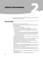
Hardware Maintenance Manual Safety information 2 This chapter contains the safety information that you need to be familiar with before servicing a computer. General safety Follow these rules to ensure general safety: •• Observe good housekeeping in the area of the machines during and after - Lenovo B300 | Lenovo IdeaCentre B300 Hardware Maintenance Manual V2.1 - Page 7
After service, power cords, telecommunication systems, networks, and modems before you open the server/workstation covers, unless instructed power-off (EPO) switch, disconnecting switch, or electrical outlet. If an electrical accident occurs, you can then operate the switch or unplug the power - Lenovo B300 | Lenovo IdeaCentre B300 Hardware Maintenance Manual V2.1 - Page 8
Manual •• If you need to work on a machine that has exposed electrical circuits, observe the following precautions: - Ensure that another person, familiar with the power-off controls, is near you. Remember: Another person must be there to switch off the power, if necessary. - Use only one - Lenovo B300 | Lenovo IdeaCentre B300 Hardware Maintenance Manual V2.1 - Page 9
had required safety items installed to protect users and service personnel from injury. This guide addresses only those items. However, good judgment should correcting the problem. Consider these conditions and the safety hazards they present: •• Electrical hazards, especially primary power (primary - Lenovo B300 | Lenovo IdeaCentre B300 Hardware Maintenance Manual V2.1 - Page 10
Hardware Maintenance Manual Handling electrostatic discharge-sensitive devices Any computer part containing a grounding system, such as those listed below, to provide protection that meets the specific service requirement. Note: The use of a grounding system is desirable but not required to protect - Lenovo B300 | Lenovo IdeaCentre B300 Hardware Maintenance Manual V2.1 - Page 11
equipment that will be attached to this product. •• When possible, use one hand only to connect or disconnect signal cables. •• Never turn on any Disconnect the attached power cords, telecommunications systems, networks, and modems before you open the device covers, unless instructed otherwise in - Lenovo B300 | Lenovo IdeaCentre B300 Hardware Maintenance Manual V2.1 - Page 12
Hardware Maintenance Manual CAUTION: When replacing the lithium battery, use only Part Number covers of the laser product could result in exposure to hazardous laser radiation. There are no serviceable parts inside the device. •• Use of controls or adjustments or performance of procedures other than - Lenovo B300 | Lenovo IdeaCentre B300 Hardware Maintenance Manual V2.1 - Page 13
CAUTION: Use safe practices when lifting. CAUTION: The power control button on the device and the power switch on the power supply do not turn off the electrical current supplied to the device. The device also might have more than one power cord. To remove all electrical current from the device - Lenovo B300 | Lenovo IdeaCentre B300 Hardware Maintenance Manual V2.1 - Page 14
Manual General information 3 This chapter provides general information that applies to all machine types supported by this publication. Specifications This section lists the physical specifications for your computer. Type Lenovo IdeaCentre B3 This section lists the physical specifications - Lenovo B300 | Lenovo IdeaCentre B300 Hardware Maintenance Manual V2.1 - Page 15
Attentions The drives in the computer you are servicing might have been rearranged or the drive startup problem: 1. Power-off the computer and all external devices. 2. Check all cables and power cords. 3. Set all display controls to the middle position. 4. Power-on all external devices. 5. Power - Lenovo B300 | Lenovo IdeaCentre B300 Hardware Maintenance Manual V2.1 - Page 16
following information to assist you in problem determination. If possible, have this information available when requesting assistance from Service Support and Engineering functions. •• Machine type and model •• Processor or hard disk upgrades •• Failure symptom - Do diagnostics indicate a failure - Lenovo B300 | Lenovo IdeaCentre B300 Hardware Maintenance Manual V2.1 - Page 17
release the F1 key rather than leaving it pressed when turning on the computer. b. If a Power-On Password or an administrator password has been set, the Setup Utility program menu is not displayed until you type your password. For more information, see"Using passwords." Viewing and changing settings - Lenovo B300 | Lenovo IdeaCentre B300 Hardware Maintenance Manual V2.1 - Page 18
have at least seven characters in length • Contain at least one alphabetic character and one numeric character • Setup Utility program and hard disk drive a password prompt is displayed each time you try to access the Setup Utility program. If both the Administrator and Power-On Password are set - Lenovo B300 | Lenovo IdeaCentre B300 Hardware Maintenance Manual V2.1 - Page 19
press Enter. Press Enter in New Password and confirm New Password dialog. A setup notice will display that changes have been saved. 3. Select Exit. 4. Select Save changes and Exit. Power-On Password When a Power-On Password is set, you cannot start the Setup Utility program until a valid password is - Lenovo B300 | Lenovo IdeaCentre B300 Hardware Maintenance Manual V2.1 - Page 20
Hardware Maintenance Manual 1. Start the Setup Utility program (See Starting the Setup Utility program .) 2. From the Security menu, select Set Power-On Password and press Enter. 3. The password dialog box will be displayed. Type the new password, and press Enter. 4. when prompted to confirm the - Lenovo B300 | Lenovo IdeaCentre B300 Hardware Maintenance Manual V2.1 - Page 21
device such as the CD-ROM, diskette, or hard disk as expected, use one of the following procedures to select a startup device. Selecting a temporary startup are using a USB keyboard and the Startup Device Menu does not display using this method, repeatedly press and release the F12 key rather than - Lenovo B300 | Lenovo IdeaCentre B300 Hardware Maintenance Manual V2.1 - Page 22
Hardware Maintenance Manual Exiting from the Setup Utility program When you finish viewing or changing settings, press Esc to return to the Setup Utility program menu (you might - Lenovo B300 | Lenovo IdeaCentre B300 Hardware Maintenance Manual V2.1 - Page 23
page 13. This index can also be used to help you decide which FRUs to have available when servicing a computer. If you are unable to correct the problem using this index, go to "Undetermined problems" on page 27. Notes • If you have both an error message and an incorrect audio response diagnose the - Lenovo B300 | Lenovo IdeaCentre B300 Hardware Maintenance Manual V2.1 - Page 24
Hardware Maintenance Manual Error The boot sector on the start-up drive is corrupted. The drive Power Supply Problems If you suspect a power problem, use the following procedures. Check/Verify Check the following for proper installation. •• Power adapter connector •• System Board Power adapter - Lenovo B300 | Lenovo IdeaCentre B300 Hardware Maintenance Manual V2.1 - Page 25
, set keyboardless operation in Setup to Enable. The BIOS then ignores the missing keyboard during POST. The system has been halted. A reset or power cycle is required to reboot the machine. This message appears after a fatal error has been detected. The BIOS was unable to find a suitable boot - Lenovo B300 | Lenovo IdeaCentre B300 Hardware Maintenance Manual V2.1 - Page 26
Maintenance Manual Undetermined problems If this computer has a parallel ATA hard disk drive, make sure that the hard disk drive is jumpered as a master and the optical drive is jumpered as a slave. 1. Power-off the computer. 2. Remove or disconnect the following components (if installed) one at - Lenovo B300 | Lenovo IdeaCentre B300 Hardware Maintenance Manual V2.1 - Page 27
Locations 7Chapter 7. Locations This section provides illustrations to help locate the various connectors, controls and components of the computer. Locating components and connectors The following illustrations will help you to locate the various components and connectors in your computer. - Lenovo B300 | Lenovo IdeaCentre B300 Hardware Maintenance Manual V2.1 - Page 28
Maintenance Manual 1 Computer stand 2 Computer cover 3 Motherboard 4 Shell 5 Plastic frame 6 Chassis 7 LED panel 8 Front bezel 9 Camera 10 Optical disk drive 11 Hard disk drive 12 Motherboard cover 13 System fan 14 Heatsink 15 Function panel 16 Invert board 17 WLAN module 18 Bluetooth module - Lenovo B300 | Lenovo IdeaCentre B300 Hardware Maintenance Manual V2.1 - Page 29
6 Headphone connector 7 Microphone connector 8 USB connector 9 Speaker connectors 10 USB connectors (4) 11 Ethernet connector 12 1394 connector 13 PS/2 keyboard connector 14 Power connector 15 WLAN connector 16 TV tuner card connector 17 Power button connector 18 Function panel connector 19 SATA - Lenovo B300 | Lenovo IdeaCentre B300 Hardware Maintenance Manual V2.1 - Page 30
Hardware Maintenance Manual 21 SATA connector 22 LED panel connector 28 - Lenovo B300 | Lenovo IdeaCentre B300 Hardware Maintenance Manual V2.1 - Page 31
in the Hardware Maintenance Manual (HMM) for the computer. To obtain copies of the Safety and Warranty Guide or HMM, go to the Support Web site at: http://consumersupport.lenovo.com. Note Use only parts provided by Lenovo. General information Pre-disassembly instructions Before proceeding with the - Lenovo B300 | Lenovo IdeaCentre B300 Hardware Maintenance Manual V2.1 - Page 32
from scratches or other damage. 1. Remove any media (diskettes, CDs, or memory cards) from the drives, shut down the operating system, turn off all attached devices, and the computer. 2. Unplug all power cords from electrical outlets. 3. Disconnect all cables attached to the computer. This includes - Lenovo B300 | Lenovo IdeaCentre B300 Hardware Maintenance Manual V2.1 - Page 33
Chapter 8. Replacing hardware 1 2 5. Remove the 2 screws that secure the computer stand to the chassis. 6. Slide out the computer stand. 4 3 3 Warning When finish replacing a FRU, follow the below instructions to install back computer stand. Incorrect operations may damage the computer stand. 31 - Lenovo B300 | Lenovo IdeaCentre B300 Hardware Maintenance Manual V2.1 - Page 34
Hardware Maintenance Manual To reinstall the computer stand 1. Align then slide the computer stand back Note For this procedure, it helps to place the computer face-down on a soft flat surface. Lenovo recommends that you use a blanket, towel, or other soft cloth to protect the touch screen surface from - Lenovo B300 | Lenovo IdeaCentre B300 Hardware Maintenance Manual V2.1 - Page 35
To replace the memory module: 1. Remove any media (diskettes, CDs, or memory cards) from the drives, shut down the operating system, turn off all attached devices, and the computer. 2. Unplug all power cords from electrical outlets. 3. Disconnect all cables attached to the computer. This includes - Lenovo B300 | Lenovo IdeaCentre B300 Hardware Maintenance Manual V2.1 - Page 36
Hardware Maintenance Manual 7. Push out the latches on both sides of the memory socket to release the memory module and gently pull the memory module upward to remove - Lenovo B300 | Lenovo IdeaCentre B300 Hardware Maintenance Manual V2.1 - Page 37
it helps to place the computer face-down on a soft flat surface. Lenovo recommends that you use a blanket, towel, or other soft cloth to protect or memory cards) from the drives, shut down the operating system, turn off all attached devices, and the computer. 2. Unplug all power cords from - Lenovo B300 | Lenovo IdeaCentre B300 Hardware Maintenance Manual V2.1 - Page 38
Hardware Maintenance Manual 8. Remove the optical drive cover place the computer face-down on a soft flat surface. Lenovo recommends that you use a blanket, towel, or other soft cards) from the drives, shut down the operating system, turn off all attached devices, and the computer. 2. Unplug all power - Lenovo B300 | Lenovo IdeaCentre B300 Hardware Maintenance Manual V2.1 - Page 39
Chapter 8. Replacing hardware 3. Disconnect all cables attached to the computer. This includes power cords, input/output (I/O) cables, and any other cables that are connected to the computer. Refer to "Locating connectors on the rear of the computer". 4. Remove - Lenovo B300 | Lenovo IdeaCentre B300 Hardware Maintenance Manual V2.1 - Page 40
Manual To replace the hard disk drive: Note For this procedure, it helps to place the computer face-down on a soft flat surface. Lenovo computer cover. Refer to "Removing the computer cover". 3. Disconnect the data and power cables from the hard disk drive. 4. Remove the 4 screws that secure the - Lenovo B300 | Lenovo IdeaCentre B300 Hardware Maintenance Manual V2.1 - Page 41
(2) Screw back the 4 screws on the drive bay. 8. Connect the data and power cables back to the hard disk drive. 9. Align the 4 screw holes in the 10. Install the computer cover and stand. Replacing the bluetooth module To replace the bluetooth module: 1. Remove the computer stand. Refer to "Removing - Lenovo B300 | Lenovo IdeaCentre B300 Hardware Maintenance Manual V2.1 - Page 42
Hardware Maintenance Manual 4. Disconnect the antenna cable from the bluetooth module. 5. Connect the antenna cable to the new bluetooth module. 6. Align then use double-sided sticky tape stick the bluetooth module back. 7. Install the computer cover and stand. Removing the motherboard cover 1. - Lenovo B300 | Lenovo IdeaCentre B300 Hardware Maintenance Manual V2.1 - Page 43
heatsink: 1. Removing the computer stand. Refer to "Removing the computer stand". 2. Removing the computer cover. Refer to "Removing the computer cover". 3. Removing the motherboard cover. Refer to "Removing the motherboard cover". 4. Remove the 4 screws that secure the heatsink to the chassis. 41 - Lenovo B300 | Lenovo IdeaCentre B300 Hardware Maintenance Manual V2.1 - Page 44
Maintenance Manual 5. Lift up the heatsink. 6. Align then install the new heatsink. 7. Align then install the motherboard cover motherboard cover. Refer to "Removing the motherboard cover". 4. Remove the heatsink. Refer to "Replacing the heatsink". 5. Disconnect the power cable from the motherboard - Lenovo B300 | Lenovo IdeaCentre B300 Hardware Maintenance Manual V2.1 - Page 45
the system fan out and lift it up to remove it. 8. Align then install the new system fan. 9. Align then install the heatsink & the motherboard cover back. 10. Align then install the computer cover and computer stand. Replacing the microprocessor Important Do not touch the gold contact on the bottom - Lenovo B300 | Lenovo IdeaCentre B300 Hardware Maintenance Manual V2.1 - Page 46
Hardware Maintenance Manual 6. Lift the microprocessor out of the retainer. 7. Align then place the new microprocessor back and lock the retainer properly with the handle. 8. Align then install the heatsink and the motherboard cover. 9. Install the computer cover and computer stand. Replacing the - Lenovo B300 | Lenovo IdeaCentre B300 Hardware Maintenance Manual V2.1 - Page 47
the new function panel. 7. Connect the cable to the new function panel. 8. Install the computer cover and computer stand. Replacing the WLAN card card 1. Remove the computer stand. Refer to "Removing the computer stand". 2. Remove the computer cover. Refer to "Removing the computer cover". 3. Remove - Lenovo B300 | Lenovo IdeaCentre B300 Hardware Maintenance Manual V2.1 - Page 48
Hardware Maintenance Manual 5. Remove the screw that secures the WLAN card to motherboard, and pull out the WLAN card. 6. Align then insert the new WLAN card to the card port and screw it in to the motherboard. 7. Connect the antenna cables back to the new WLAN card. 8. Install the motherboard cover - Lenovo B300 | Lenovo IdeaCentre B300 Hardware Maintenance Manual V2.1 - Page 49
system. Chapter 8. Replacing hardware 7. Align then screw in the new speakers system. 8. Connect the new speakers cables to the motherboard. 9. Install the motherboard cover back. 10. Install the computer cover and computer stand. Removing the inverter board To remove the inverter board 1. Remove - Lenovo B300 | Lenovo IdeaCentre B300 Hardware Maintenance Manual V2.1 - Page 50
Hardware Maintenance Manual 6. Disconnect all the cables from the inverter board and slide out to "Removing the computer cover". 3. Remove the motherboard cover. Refer to "Removing the motherboard cover". 4. Disconnect the antenna cable from the TV tuner card. 5. Remove the screw that secures the TV - Lenovo B300 | Lenovo IdeaCentre B300 Hardware Maintenance Manual V2.1 - Page 51
Chapter 8. Replacing hardware 6. Pull the TV tuner card upward to remove it from the card port. 7. Align then screw in the new TV tuner card. 8. Connect the antenna cable to the new TV tuner card. 9. Screw back the motherboard cover. 10. Install the computer cover and screw back the computer stand. - Lenovo B300 | Lenovo IdeaCentre B300 Hardware Maintenance Manual V2.1 - Page 52
". 7. Remove the WLAN card. Refer to "Replacing the WLAN card". 8. Remove the TV tuner card. Refer to "Replacing the TV tuner card". 9. Remove the TV antenna connector. Refer to "Removing the TV antenna connector". 10. Remove all the cables that connected to the motherboard. 11. Remove the - Lenovo B300 | Lenovo IdeaCentre B300 Hardware Maintenance Manual V2.1 - Page 53
to the chassis. 15. Install all related components back to the new motherboard. 16. Connect all the cables to the new motherboard. 17. Screw back the motherboard cover. 18. Install the computer cover and screw back the computer stand. Removing the shell To remove the back shell: 1. Remove - Lenovo B300 | Lenovo IdeaCentre B300 Hardware Maintenance Manual V2.1 - Page 54
Hardware Maintenance Manual 4. Lift up the shell. Replacing the camera To replace the camera 1. Remove the computer stand. Refer to "Removing the computer stand". 2. Remove the computer cover. - Lenovo B300 | Lenovo IdeaCentre B300 Hardware Maintenance Manual V2.1 - Page 55
Chapter 8. Replacing hardware 6. Disconnect the cable from the camera. 4. Connect the cable to the new camera. 5. Align then screw in the new camera. 6. Align then screw back the shell. 7. Install the computer cover and screw back the computer stand. Replacing the touch module To replace the touch - Lenovo B300 | Lenovo IdeaCentre B300 Hardware Maintenance Manual V2.1 - Page 56
Hardware Maintenance Manual 6. Disconnect the cables from the touch module. 4 4 7. Reconnect the computer cover. Refer to "Removing the computer cover". 4. Remove the motherboard cover. Refer to "Removing the motherboard cover". 5. Remove the touch module. Refer to "Replacing the touch module - Lenovo B300 | Lenovo IdeaCentre B300 Hardware Maintenance Manual V2.1 - Page 57
Chapter 8. Replacing hardware 7. Disconnect the LED cable from the LED panel. 8. Remove the shell. Refer to "Removing the shell". 9. Remove the 6 screws that secure chassis to the front bezel. 10. Pull the pins to release the chassis from the front bezel. 11. Place the computer upside down and - Lenovo B300 | Lenovo IdeaCentre B300 Hardware Maintenance Manual V2.1 - Page 58
Hardware Maintenance Manual 12. Remove the 4 screws that secure the LED panel to the Chassis. 13. Lift up LED panel and disconnect the cable that connected to the - Lenovo B300 | Lenovo IdeaCentre B300 Hardware Maintenance Manual V2.1 - Page 59
computer or in the Hardware Maintenance Manual (HMM) for the computer. To obtain copies of the Safety and Warranty Guide or HMM, go to the Support Web site at: http://consumersupport.lenovo.com. To replace the keyboard: 1. Remove any media (diskettes, CDs, or memory cards) from the drives, shut down - Lenovo B300 | Lenovo IdeaCentre B300 Hardware Maintenance Manual V2.1 - Page 60
computer or in the Hardware Maintenance Manual (HMM) for the computer. To obtain copies of the Safety and Warranty Guide or HMM, go to the Support Web site at: http://consumersupport.lenovo.com. To replace the mouse: 1. Remove any media (diskettes, CDs, or memory cards) from the drives, shut down - Lenovo B300 | Lenovo IdeaCentre B300 Hardware Maintenance Manual V2.1 - Page 61
or in the Hardware Maintenance Manual (HMM) for the computer. To obtain copies of the Safety and Warranty Guide or HMM, go to the Support Web site at: http://consumersupport.lenovo.com. To replace the power cord and power adapter: 1. Remove any media (diskettes, CDs, or memory cards) from the drives - Lenovo B300 | Lenovo IdeaCentre B300 Hardware Maintenance Manual V2.1 - Page 62
Hardware Maintenance Manual Additional Service Information 9 This chapter provides additional information that the service representative might find helpful. Power management Power management reduces the power consumption of certain components of the computer such as the system power supply, - Lenovo B300 | Lenovo IdeaCentre B300 Hardware Maintenance Manual V2.1 - Page 63
according to the instructions and requirements described in the manuals included with your computer. Lenovo will not assume responsibility for any loss incurred except those resulting from installation or operations carried out by Lenovo professional service staff. Lenovo has made every attempt - Lenovo B300 | Lenovo IdeaCentre B300 Hardware Maintenance Manual V2.1 - Page 64
table above includes the logo and registered trademarks of Lenovo and its partners. Other registered trademarks mentioned in any or all of the manuals included with your computer belong to the specific company respectively. The manual included with your computer is protected by copyright laws and
-
 1
1 -
 2
2 -
 3
3 -
 4
4 -
 5
5 -
 6
6 -
 7
7 -
8
-
9
-
10
-
11
-
12
-
13
-
14
-
15
-
16
-
17
-
18
-
19
-
20
-
21
-
22
-
23
-
24
-
25
-
26
-
27
-
28
-
29
-
30
-
31
-
32
-
33
-
34
-
35
-
36
-
37
-
38
-
39
-
40
-
41
-
42
-
43
-
44
-
45
-
46
-
47
-
48
-
49
-
50
-
51
-
52
-
53
-
54
-
55
-
56
-
57
-
58
-
59
-
60
-
61
-
62
-
63
-
64
 |
 |

Contents
i
Contents
Chapter 1. About this manual
................................................
1
Important
Safety Information
......................................................................
1
Important information about replacing RoHS compliant FRUs ..2
Chapter 2. Safety information
................................................
4
General safety
.......................................................................................................
4
Electrical safety
....................................................................................................
5
Safety inspection guide
...................................................................................
7
Handling electrostatic discharge-sensitive devices
.........................
8
Grounding requirements
...............................................................................
8
Safety notices
........................................................................................................
9
Chapter 3. General information
...........................................
12
Specifications
.....................................................................................................
12
Chapter 4. General Checkout
...............................................
13
Problem determination tips
.......................................................................
14
Chapter 5. Using the Setup Utility
......................................
15
Starting the Setup Utility program
.........................................................
15
Viewing and changing settings
................................................................
15
Using passwords
..............................................................................................
16
Using Device
......................................................................................................
18
Selecting a startup device
...........................................................................
19
Exiting from the Setup Utility program
................................................
20
Chapter 6. Symptom-to-FRU Index
.....................................
21
Hard disk drive boot error
...........................................................................
21