Lenovo D400 Lenovo IdeaCentre D400 Series Hardware Maintenance Manual
Lenovo D400 Manual
 |
View all Lenovo D400 manuals
Add to My Manuals
Save this manual to your list of manuals |
Lenovo D400 manual content summary:
- Lenovo D400 | Lenovo IdeaCentre D400 Series Hardware Maintenance Manual - Page 1
Lenovo IdeaCentre D400 Series Hardware Maintenance Manual - Lenovo D400 | Lenovo IdeaCentre D400 Series Hardware Maintenance Manual - Page 2
- Lenovo D400 | Lenovo IdeaCentre D400 Series Hardware Maintenance Manual - Page 3
ii - Lenovo D400 | Lenovo IdeaCentre D400 Series Hardware Maintenance Manual - Page 4
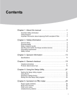
Utility 21 Starting the Setup Utility program 21 Using device 22 Selecting a startup device 23 Exiting from the Setup Utility program 23 Chapter 6. Symptom-to-FRU index 25 Power supply problems 26 BIOS crisis recovery 26 POST error codes 27 Undetermined - Lenovo D400 | Lenovo IdeaCentre D400 Series Hardware Maintenance Manual - Page 5
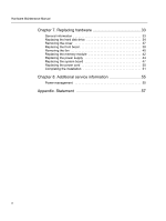
Replacing the front bezel 38 Removing the fan 40 Replacing the memory module 42 Replacing the power supply 44 Replacing the system board 47 Replacing the power cord 50 Completing the installation 51 Chapter 8. Additional service information 55 Power management 55 Appendix. Statement 57 iii - Lenovo D400 | Lenovo IdeaCentre D400 Series Hardware Maintenance Manual - Page 6
Lenovo IdeaCentre A computers listed on the cover. It is intended only for trained servicers who are familiar with Lenovo computer products. Before servicing a Lenovo product, be sure to read the Safety Information. This manual includes a complete FRU d'exécuter les instructions. Lesen Sie unbedingt - Lenovo D400 | Lenovo IdeaCentre D400 Series Hardware Maintenance Manual - Page 7
manual Using eSupport For Key Commodities (Examples - hard disk drive, system board, microprocessor, LCD, and memory) • eSupport can be used to view the list of key commodities built in a particular machine serial. • eSupport can be accessed at the following Web site: http://consumersupport.lenovo - Lenovo D400 | Lenovo IdeaCentre D400 Series Hardware Maintenance Manual - Page 8
ready to support Lenovo's requirements and schedule. Products sold in 2005, will contain some RoHS compliant FRUs. The following statement pertains to these products and any product Lenovo produces containing RoHS compliant parts. RoHS compliant Lenovo IdeaCentre A parts have unique FRU part numbers - Lenovo D400 | Lenovo IdeaCentre D400 Series Hardware Maintenance Manual - Page 9
Chapter 1. About this manual 4 - Lenovo D400 | Lenovo IdeaCentre D400 Series Hardware Maintenance Manual - Page 10
and the customer's personnel are not in a hazardous position. • Place removed covers and other parts in a safe place, away from all personnel, while you are servicing the machine. • Keep your tool case away from walk areas so that other people will not trip over it. • Do not wear loose clothing that - Lenovo D400 | Lenovo IdeaCentre D400 Series Hardware Maintenance Manual - Page 11
in any other conditions that might be hazardous to your eyes. • After service, reinstall all safety shields, guards, labels, and ground wires. Replace any attached power cords, telecommunication systems, networks, and modems before you open the server/workstation covers, unless instructed otherwise - Lenovo D400 | Lenovo IdeaCentre D400 Series Hardware Maintenance Manual - Page 12
safety precautions when you work with very high voltages; these instructions are in the safety sections of maintenance information. Use extreme . • Do not service the following parts with the power on when they are removed from their normal operating places in a machine: - Power supply units - Pumps - Lenovo D400 | Lenovo IdeaCentre D400 Series Hardware Maintenance Manual - Page 13
had required safety items installed to protect users and service personnel from injury. This guide addresses only those items. However, good judgment should correcting the problem. Consider these conditions and the safety hazards they present: • Electrical hazards, especially primary power (primary - Lenovo D400 | Lenovo IdeaCentre D400 Series Hardware Maintenance Manual - Page 14
Hardware Maintenance Manual Handling electrostatic discharge-sensitive devices Any computer part containing Select a grounding system, such as those listed below, to provide protection that meets the specific service requirement. Note: The use of a grounding system is desirable but not required to - Lenovo D400 | Lenovo IdeaCentre D400 Series Hardware Maintenance Manual - Page 15
when there is evidence of fire, water, or structural damage. • Disconnect the attached power cords, telecommunications systems, networks, and modems before you open the device covers, unless instructed otherwise in the installation and configuration procedures. • Connect and disconnect cables as - Lenovo D400 | Lenovo IdeaCentre D400 Series Hardware Maintenance Manual - Page 16
Manual CAUTION ordinances or regulations. CAUTION: When laser products (such as CD-ROMs, DVD-ROM drives, fiber optic devices, or transmitters) are installed, note the result in exposure to hazardous laser radiation. There are no serviceable parts inside the device. • Use of controls or adjustments - Lenovo D400 | Lenovo IdeaCentre D400 Series Hardware Maintenance Manual - Page 17
18 kg(37 lbs) 32 kg(70.5 lbs) 55 kg(121.2 lbs) CAUTION: Use safe practices when lifting. CAUTION: The power control button on the device and the power switch on the power supply do not turn off the electrical current supplied to the device. The device also might have more than one - Lenovo D400 | Lenovo IdeaCentre D400 Series Hardware Maintenance Manual - Page 18
general information that applies to all machine types supported by this publication. Specifications This section lists the physical specifications for your computer. Type Lenovo IdeaCentre Q500 Series This section lists the physical specifications. Environment Air temperature: Operating: 10° to 35 - Lenovo D400 | Lenovo IdeaCentre D400 Series Hardware Maintenance Manual - Page 19
Chapter 3. General information 14 - Lenovo D400 | Lenovo IdeaCentre D400 Series Hardware Maintenance Manual - Page 20
external devices. 4. Power-on the home center. • Inspect the LED indicators on the front panel, which can indicate the malfunction. See the User Guide for information about the LED indicators. • Look for displayed error codes. Refer to "POST error codes". • Look for readable instructions or a main - Lenovo D400 | Lenovo IdeaCentre D400 Series Hardware Maintenance Manual - Page 21
at the following conditions and follow the instructions: • If an error code is displayed during POST, go to "POST error codes" • If the home center hangs and no error is displayed, continue to step 7. 6. Inspect internal components and cables a. Power off the home center and all external devices - Lenovo D400 | Lenovo IdeaCentre D400 Series Hardware Maintenance Manual - Page 22
for diagnosing hardware problems, review the following information: • Read the safety information. Go to "Safety information". • The diagnostic program provides the primary methods of testing the major components on the home center, such as the hard disk drives, fan, memory module, processor and - Lenovo D400 | Lenovo IdeaCentre D400 Series Hardware Maintenance Manual - Page 23
PQAF memory test PQAF HDD test Read serial number from DMI data Pass 7. After the diagnostic routine is completed, the HDD status indicator lights purple indicating the system passed all diagnostic tests. 8. A copy of the test result will be saved as a log file and stored in the Results folder - Lenovo D400 | Lenovo IdeaCentre D400 Series Hardware Maintenance Manual - Page 24
Maintenance Manual Problem determination tips Due to the variety of hardware and software combinations that can be encountered, use the following information to assist you in problem determination. If possible, have this information available when requesting assistance from Service Support and - Lenovo D400 | Lenovo IdeaCentre D400 Series Hardware Maintenance Manual - Page 25
Chapter 4. General checkout 20 - Lenovo D400 | Lenovo IdeaCentre D400 Series Hardware Maintenance Manual - Page 26
Setup Utility program. Starting the Setup Utility program To start the Setup Utility program, do the following: 1. Power off the home center and all external devices. 2. Unplug all cables and power cord. 3. Place the system unit on a flat, stable surface. 4. Remove the cover. Refer to "Removing the - Lenovo D400 | Lenovo IdeaCentre D400 Series Hardware Maintenance Manual - Page 27
7. Close the jumper to enable system for debug mode. 8. Connect the power cable to the rear panel. 9. Connect a USB keyboard to the debug board. 10. the home center. 12.Turn on the monitor. 13.During POST, press F2. If you fail to press F2 before POST is completed, you need to restart the server. - Lenovo D400 | Lenovo IdeaCentre D400 Series Hardware Maintenance Manual - Page 28
Maintenance Manual Serial ATA Enables or disables the onboard SATA ports. The default is set to Enabled. To enable the onboard SATA ports: select Exit Discarding Changes from the Exit menu. Selecting a startup device If the home center does not start up (boot) from the hard disk, use the procedure - Lenovo D400 | Lenovo IdeaCentre D400 Series Hardware Maintenance Manual - Page 29
Chapter 5. Using the Setup Utility 24 - Lenovo D400 | Lenovo IdeaCentre D400 Series Hardware Maintenance Manual - Page 30
-to-FRU index lists error symptoms and possible causes. The most likely cause is listed first. Always begin with Chapter 4, "General Checkout," on page 13. This index can also be used to help you decide which FRUs to have available when servicing a computer. If you are unable to correct the problem - Lenovo D400 | Lenovo IdeaCentre D400 Series Hardware Maintenance Manual - Page 31
following for proper installation. • Power Cord • Switch connector • System Board Power Supply connectors Check the power cord for continuity Check the power-on switch for continuity. FRU/Action Reseat connectors Power Cord Power-on Switch BIOS crisis recovery When the home center's BIOS fails or - Lenovo D400 | Lenovo IdeaCentre D400 Series Hardware Maintenance Manual - Page 32
of the home center and some options. This series of tests is called the Power-On Self-Test, or POST. POST does the following operations. • Checks some basic system board operations • Checks the memory operation • Verifies that the boot drive is working If the POST detects a problem with a hardware - Lenovo D400 | Lenovo IdeaCentre D400 Series Hardware Maintenance Manual - Page 33
FRU are connected to the home center. 3. Make sure the front USB port cable is installed home center. The network LED indicates whether there is a problem with the connector or cable. See the User Guide fan. Memory failed 1. Make sure the DIMM is installed correctly. See "Replacing the memory module". - Lenovo D400 | Lenovo IdeaCentre D400 Series Hardware Maintenance Manual - Page 34
Hardware Maintenance Manual Operating condition After system boot Bit 0 Error code Bit 1 Bit 2 the system board 2. Replace the following components one at a time, in the order shown, restarting the home center each time: - Hard disk drive - Cable from the hard disk drive backplane to the system - Lenovo D400 | Lenovo IdeaCentre D400 Series Hardware Maintenance Manual - Page 35
If you suspect that a software problem is causing failures, see the User Guide. Damaged data in CMOS memory can cause undetermined problems. To reset the CMOS data, use the CMOS jumper to clear the CMOS memory. To reset the CMOS data: 1. Power off the home center and all external devices. 2. Unplug - Lenovo D400 | Lenovo IdeaCentre D400 Series Hardware Maintenance Manual - Page 36
Hardware Maintenance Manual 3. Power-on the home center to re-test the system. 4. Repeat steps 1 through 3 until you find the failing device or adapter. If all devices and adapters have been removed, and the problem continues, replace the system board. 31 - Lenovo D400 | Lenovo IdeaCentre D400 Series Hardware Maintenance Manual - Page 37
Chapter 5. Symptom-to-FRU index 32 - Lenovo D400 | Lenovo IdeaCentre D400 Series Hardware Maintenance Manual - Page 38
and Warranty Guide or HMM, go to the Support Web site at: http://consumersupport.lenovo.com. Note Use only parts provided by Lenovo. General information Pre-disassembly instructions Before proceeding with the disassembly procedure, make sure that you do the following: 1. Power-off the home center - Lenovo D400 | Lenovo IdeaCentre D400 Series Hardware Maintenance Manual - Page 39
Replacing the hard disk drive To replace the hard disk drive 1. Open the door of the home center. Chapter 7. Replacing hardware 2. Remove the HDD carrier by pressing the HDD carrier latch. 34 - Lenovo D400 | Lenovo IdeaCentre D400 Series Hardware Maintenance Manual - Page 40
Hardware Maintenance Manual 3. Pull the lever and slide the HDD carrier from the chassis. 4. Remove the HDD from the carrier. (1) Gently pry open the left side rail. (2) Remove the drive from the carrier. 1 1 2 35 - Lenovo D400 | Lenovo IdeaCentre D400 Series Hardware Maintenance Manual - Page 41
Chapter 7. Replacing hardware 5. Install the new HDD into the carrier. (1) Insert the new drive into the right side of the carrier, aligning the pins with the HDD's mounting holes. (2) Slightly bend the left side rail and insert the pins into the HDD's mounting holes. 1 1 2 2 (3) With the lever - Lenovo D400 | Lenovo IdeaCentre D400 Series Hardware Maintenance Manual - Page 42
Hardware Maintenance Manual Removing the cover Attention Turn off the home center and wait 3 to 5 minutes to let the home center cool before removing the cover. To remove the cover 1. Read the safety information in the User Guide document. 2. Unplug all power cords from electrical outlets. 3. - Lenovo D400 | Lenovo IdeaCentre D400 Series Hardware Maintenance Manual - Page 43
Chapter 7. Replacing hardware Replacing the front bezel To replace the front bezel 1. Remove the cover. Refer to "Removing the cover". 2. Slightly press the right-side retention tabs and gently push in to release the bezel from the home center, as shown. 3. Do the same on the other side. 38 - Lenovo D400 | Lenovo IdeaCentre D400 Series Hardware Maintenance Manual - Page 44
Hardware Maintenance Manual 4. Disconnect the switch cable (1) and the I/O LED cable (2) from the front panel LED board. 5. Remove the front bezel. 7. Align the bezel tabs with the notches on the front of the home center, then snap the bezel in place. 8. Refer to "Completing the installation". 39 - Lenovo D400 | Lenovo IdeaCentre D400 Series Hardware Maintenance Manual - Page 45
included with your computer or in the Hardware Maintenance Manual (HMM) for the home center. To obtain copies of the Safety and Warranty Guide or HMM, go to the Support Web site at http://consumersupport.lenovo.com. To replace the fan 1. Remove the cover. Refer to "Removing the cover". 2. Disconnect - Lenovo D400 | Lenovo IdeaCentre D400 Series Hardware Maintenance Manual - Page 46
Hardware Maintenance Manual 3. Remove the four screws (1) that secure the fan to the home center chassis. 4. Remove the fan (2) from the home center. 5. Align the four screw holes on the new fan to the four mounting holes on the home center chassis. 6. Secure the new fan with four screws. 7. - Lenovo D400 | Lenovo IdeaCentre D400 Series Hardware Maintenance Manual - Page 47
3. Slide the system board tray out of the home center chassis. (1) Insert your thumb into the thumb hole, then press in the tab to release the system board tray. (2) Pull the tray out until you can gain access to the memory connector. 4. Remove the memory module. (1) Open the retaining clips on both - Lenovo D400 | Lenovo IdeaCentre D400 Series Hardware Maintenance Manual - Page 48
Hardware Maintenance Manual 5. Install the new memory module. (1) Align then insert the new memory module into the connector. (2) Push down on the top edge of the memory module. Make sure the retaining clips latches lock the memory module in place. 6. Slide the system board tray into the chassis. 7. - Lenovo D400 | Lenovo IdeaCentre D400 Series Hardware Maintenance Manual - Page 49
Chapter 7. Replacing hardware Replacing the power supply To replace the power supply 1. Remove the cover. Refer to "Removing the cover". 2. Remove the front bezel. Refer to "Replacing the front bezel". 3. Untie the cable ties, as shown. 44 - Lenovo D400 | Lenovo IdeaCentre D400 Series Hardware Maintenance Manual - Page 50
Manual 4. Disconnect the power cables. (1) Pry the retaining clip out (1) and detach the 8-pin power cable (2). (2) Press down on the small tab on the 4-pin power cable (1) and pull the cable out (2). (3) Slide the system board tray out of the chassis. Refer to step 3 of the "Replacing the memory - Lenovo D400 | Lenovo IdeaCentre D400 Series Hardware Maintenance Manual - Page 51
Remove the four screws on the power supply (1). 6. Slide the power supply module out of the bay (2), as shown. 7. Slide the new power supply module into the bay. 8. Secure the new power supply to the home center with four screws. 9. Reconnect the three power cables to the hard disk drive backplane - Lenovo D400 | Lenovo IdeaCentre D400 Series Hardware Maintenance Manual - Page 52
"Replacing the front bezel". 3. Remove the fan. Refer to "Removing the fan". 4. Remove the memory module. Refer to "Replacing the memory module". 5. Remove the power supply. Refer to "Replacing the power supply". 6. Remove the backplane bracket. (1) Detach the four SATA cables from the system board - Lenovo D400 | Lenovo IdeaCentre D400 Series Hardware Maintenance Manual - Page 53
the backplane bracket out of the chassis (2). 7. Pull the system board tray out until you gain access to the HDD status LED and front USB port cables. 8. Disconnect the HDD status LED cable and the front USB port cable from the system board, then slide the tray out of the chassis. 48 - Lenovo D400 | Lenovo IdeaCentre D400 Series Hardware Maintenance Manual - Page 54
Hardware Maintenance Manual 9. Remove the system board. (1) Remove the four screws that secure the system board to the system board tray. (2) Lift the system board off the tray. - Lenovo D400 | Lenovo IdeaCentre D400 Series Hardware Maintenance Manual - Page 55
Chapter 7. Replacing hardware Replacing the power cord To replace the power cord 1. Power-off the home center and all external devices. 2. Disconnect the failing power cord from the home center and connect the new power cord to the same connector. 3. Refer to "Completing the installation". 50 - Lenovo D400 | Lenovo IdeaCentre D400 Series Hardware Maintenance Manual - Page 56
Maintenance Manual Completing the installation After replacing the parts, you need to install the cover and reconnect cables, including wired internet and power cords. 1. Ensure that all components have been reassembled correctly and that no tools or loose screws are left inside the home center - Lenovo D400 | Lenovo IdeaCentre D400 Series Hardware Maintenance Manual - Page 57
5 2 SATA 2 cable 6 3 SATA 3 cable 7 4 SATA 4 cable I/O LED, USB, and switch cables Cable HDD status LED cable Fan cable Backplane LED cable No. Cable 1 Front USB port cable 2 I/O LED cable 3 Switch cable 52 - Lenovo D400 | Lenovo IdeaCentre D400 Series Hardware Maintenance Manual - Page 58
Hardware Maintenance Manual 3. Replace the cover. (1) Position the cover on the home center chassis so screws on the cover. 4. Reconnect the external cables and power cords into the home center. Note In most areas of the world, Lenovo requires the return of the defective CRU. Information about this - Lenovo D400 | Lenovo IdeaCentre D400 Series Hardware Maintenance Manual - Page 59
Chapter 7. Replacing hardware 54 - Lenovo D400 | Lenovo IdeaCentre D400 Series Hardware Maintenance Manual - Page 60
information This chapter provides additional information that the service representative might find helpful. Power management Power management reduces the power consumption of certain components of the computer such as the system power supply, processor, hard disk drives, USB keyboard or mouse - Lenovo D400 | Lenovo IdeaCentre D400 Series Hardware Maintenance Manual - Page 61
Chapter 7. Additional service information 56 - Lenovo D400 | Lenovo IdeaCentre D400 Series Hardware Maintenance Manual - Page 62
instructions and requirements in all the manuals included with your computer, or operate the product inappropriately for reasons such as misunderstanding, Lenovo operations carried out by Lenovo professional service staff. Lenovo has performed strict collation for all the manuals included with your - Lenovo D400 | Lenovo IdeaCentre D400 Series Hardware Maintenance Manual - Page 63
description of trademarks or registered trademarks of Lenovo and its partners. Other registered trademarks mentioned in all the manuals included with your computer belong to the specific company respectively. All rights reserved. All the manuals included with your computer is protected by copyright
-
 1
1 -
 2
2 -
 3
3 -
 4
4 -
 5
5 -
 6
6 -
 7
7 -
8
-
9
-
10
-
11
-
12
-
13
-
14
-
15
-
16
-
17
-
18
-
19
-
20
-
21
-
22
-
23
-
24
-
25
-
26
-
27
-
28
-
29
-
30
-
31
-
32
-
33
-
34
-
35
-
36
-
37
-
38
-
39
-
40
-
41
-
42
-
43
-
44
-
45
-
46
-
47
-
48
-
49
-
50
-
51
-
52
-
53
-
54
-
55
-
56
-
57
-
58
-
59
-
60
-
61
-
62
-
63
 |
 |

Lenovo
IdeaCentre D400 Series
Hardware Maintenance Manual