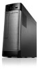
Lenovo H535s Lenovo H535s Hardware Maintenance Manual
Lenovo H535s Manual
 |
View all Lenovo H535s manuals
Add to My Manuals
Save this manual to your list of manuals |
Lenovo H535s manual content summary:
- Lenovo H535s | Lenovo H535s Hardware Maintenance Manual - Page 1
Lenovo H535s Hardware Maintenance Manual ideaideaideaCentreidea Machine Types: 10118/6286 [H535s ES]; 10119/6287 [H535s Non-ES] - Lenovo H535s | Lenovo H535s Hardware Maintenance Manual - Page 2
- Lenovo H535s | Lenovo H535s Hardware Maintenance Manual - Page 3
Lenovo H535s Hardware Maintenance Manual Machine Types: 10118/6286 [H535s ES]; 10119/6287 [H535s Non-ES] - Lenovo H535s | Lenovo H535s Hardware Maintenance Manual - Page 4
First Edition (December 2012)30th © Copyright Lenovo 2012. LIMITED AND RESTRICTED RIGHTS NOTICE: If data or software are delivered pursuant a General Services Administration "GSA" contract, use, reproduction, or disclosure is subject to restrictions set forth in Contract No. GS-35F-05925 - Lenovo H535s | Lenovo H535s Hardware Maintenance Manual - Page 5
the graphic card 35 Replacing the microprocessor fan 37 Replacing the heat-sink 37 Replacing the Wi-Fi card 38 Replacing the front USB/card reader/audio module 39 Replacing the motherboard 40 Chapter 9. General information . . . . 43 Additional Service Information 43 © Copyright Lenovo 2012 - Lenovo H535s | Lenovo H535s Hardware Maintenance Manual - Page 6
iv Lenovo H535sHardware Maintenance Manual - Lenovo H535s | Lenovo H535s Hardware Maintenance Manual - Page 7
and reference information for Lenovo H535s computers listed on the cover. It is intended only for trained servicers who are familiar with Lenovo computer products. Before servicing a Lenovo product, be sure to read the Safety Information. The description of the TV card in this manual is only used - Lenovo H535s | Lenovo H535s Hardware Maintenance Manual - Page 8
2 Lenovo H535sHardware Maintenance Manual - Lenovo H535s | Lenovo H535s Hardware Maintenance Manual - Page 9
safe place, away from all personnel, while you are servicing the machine. • Keep your tool case away from power cords, telecommunication systems, networks, and modems before you open the computer covers, unless instructed otherwise in the installation and configuration procedures. © Copyright Lenovo - Lenovo H535s | Lenovo H535s Hardware Maintenance Manual - Page 10
instructions Power supply units - Pumps - Blowers and fans - Motor generators and similar units. (This practice ensures correct grounding of the units.) • If an electrical accident occurs: - Use caution; do not become a victim yourself. - Switch off power. 4 Lenovo H535sHardware Maintenance Manual - Lenovo H535s | Lenovo H535s Hardware Maintenance Manual - Page 11
and service personnel from injury. This guide addresses power-supply cover fasteners (screws or rivets) have not been removed or tampered with. Handling electrostatic discharge-sensitive devices Any computer same charge. Notes: 1. Use product-specific ESD procedures when they exceed the requirements - Lenovo H535s | Lenovo H535s Hardware Maintenance Manual - Page 12
wrist strap. • Use the black side of a grounded work mat to provide a static-free work surface. The mat is especially useful when handling ESD-sensitive devices. • Select a grounding system, such as those listed below, to provide protection that meets the specific service requirement. Note: The use - Lenovo H535s | Lenovo H535s Hardware Maintenance Manual - Page 13
. 4. Attach power cords to outlet. 5. Turn device ON. To Disconnect 1. Turn everything OFF. 2. First, remove power cords from outlet. 3. Remove signal could result in exposure to hazardous laser radiation. There are no serviceable parts inside the device. • Use of controls or adjustments or - Lenovo H535s | Lenovo H535s Hardware Maintenance Manual - Page 14
have more than one power cord. To remove all electrical current from the device, ensure that all power cords are disconnected from the power source. 2 1 CAUTION: Do not place any object weighing more than 82 kg (180 lbs.) on top of rack-mounted devices. 8 Lenovo H535sHardware Maintenance Manual - Lenovo H535s | Lenovo H535s Hardware Maintenance Manual - Page 15
applies to all machine types supported by this publication. Specifications This section lists the physical specifications for your computer. This section lists the physical specifications for your computer. Type Lenovo H535s This section lists the physical specifications. Environment Air temperature - Lenovo H535s | Lenovo H535s Hardware Maintenance Manual - Page 16
10 Lenovo H535sHardware Maintenance Manual - Lenovo H535s | Lenovo H535s Hardware Maintenance Manual - Page 17
cause of the problem: 1. Power-off the computer and all external devices. 2. Check all cables and power cords. 3. Set all display controls to the middle position. 4. Power-on all external devices. 5. Power-on the computer. • Look for displayed error codes • Look for readable instructions or a main - Lenovo H535s | Lenovo H535s Hardware Maintenance Manual - Page 18
12 Lenovo H535sHardware Maintenance Manual - Lenovo H535s | Lenovo H535s Hardware Maintenance Manual - Page 19
this procedure, shut down the operating system and turn off the computer. 2. Press and hold the F1 key then turn on the computer. When the Lenovo BIOS Setup Utility program is displayed, release the F1 key. Note: If a Power-On Password or an Administrator Password has been set, the Setup Utility - Lenovo H535s | Lenovo H535s Hardware Maintenance Manual - Page 20
if you are responsible for maintaining the settings of several computers. After you set an Administrator Password, a password prompt is displayed every time you access the Lenovo BIOS Setup Utility program. If both the Administrator and Power-On Password are set, you can type either password - Lenovo H535s | Lenovo H535s Hardware Maintenance Manual - Page 21
-type the password to confirm, if you type the password correctly, the password will be installed. To change a Power-On Password, do the following: 1. Start the Lenovo BIOS Setup Utility program (See "Starting the Lenovo BIOS Setup Utility program" on page 13.) 2. From the Security menu, select Set - Lenovo H535s | Lenovo H535s Hardware Maintenance Manual - Page 22
Onboard Ethernet Support or LAN Boot Agent. 4. Select Disabled or Enabled and press the Enter key. 5. Return to the Lenovo BIOS Setup Utility program and release the F12 key rather than keeping it pressed when turning on the computer. 3. Use ↑ and ↓ arrows to select the desired startup device from - Lenovo H535s | Lenovo H535s Hardware Maintenance Manual - Page 23
device from or include the device in the boot sequence. 5. Return to the Lenovo BIOS Setup Utility program menu and select the Exit option. 6. Select Save changes and select the Yes button, and then press the Enter key to exit the Lenovo BIOS Setup Utility program. • If you do not want to save the - Lenovo H535s | Lenovo H535s Hardware Maintenance Manual - Page 24
18 Lenovo H535sHardware Maintenance Manual - Lenovo H535s | Lenovo H535s Hardware Maintenance Manual - Page 25
the hard disk drive. Power Supply Problems Follow these procedures if you suspect there is a power supply problem. Check/Verify Check that the following are properly installed: • Power Cord • On/Off Switch connector • System Board Power Supply connectors • Microprocessor(s) connection Check - Lenovo H535s | Lenovo H535s Hardware Maintenance Manual - Page 26
ignores the missing keyboard during POST. The BIOS was unable to find a suitable boot device. Make sure the boot drive is properly connected to the computer. Make sure you have bootable media in the boot device. Undetermined problems 1. Power-off the computer. 2. Remove or disconnect the following - Lenovo H535s | Lenovo H535s Hardware Maintenance Manual - Page 27
Chapter 7. Locating connectors, controls and components This section provides illustrations to help locate the various connectors, controls and components of the computer. © Copyright Lenovo 2012 21 - Lenovo H535s | Lenovo H535s Hardware Maintenance Manual - Page 28
the location of controls and components on the front of the computer. Attention: Be careful not to block any air vents on the computer. Blocked air vents can cause overheating. 1. Power button 2. Memory card reader (selected models only) 3. USB connectors 4. Optical drive eject button 5. Headphone - Lenovo H535s | Lenovo H535s Hardware Maintenance Manual - Page 29
rear of the computer. Lenovo H535s 11 12 1. USB 2.0 connectors 2. WiFi antenna (selected models only) 3. HDMI connector (selected models only) 4. On-board VGA connector 5. USB 3.0 connectors 6. USB 2.0 connectors 7. Ethernet connector 8. Audio connectors 9. PCI Express X 16 graphics adapter slot - Lenovo H535s | Lenovo H535s Hardware Maintenance Manual - Page 30
Hardware components The following illustration shows the components that make up your computer. Lenovo H535s 3 2 1 1. System board 2. Heatsink and CPU fan 3. Optical disk drive and bay 4 5 4. Hard disk drive 5. Power supply 24 Lenovo H535sHardware Maintenance Manual - Lenovo H535s | Lenovo H535s Hardware Maintenance Manual - Page 31
basic computing functions and supports a variety of devices that are factory-installed or that you can install later. The following illustration shows the location of connectors and components on the front of the motherboard. Lenovo H535s 1 2 3 4 5 6 16 15 14 13 1. 12V power connector - Lenovo H535s | Lenovo H535s Hardware Maintenance Manual - Page 32
26 Lenovo H535sHardware Maintenance Manual - Lenovo H535s | Lenovo H535s Hardware Maintenance Manual - Page 33
Safety and Warranty Guide that was included with your computer. To obtain copies of the Safety and Warranty Guide, go to the Support Web site at: http://consumersupport.lenovo.com. Note: Use only parts provided by Lenovo. General information Pre-disassembly instructions Before proceeding with the - Lenovo H535s | Lenovo H535s Hardware Maintenance Manual - Page 34
media (disks, CDs, DVDs or memory cards) from the drives, shut down the operating system, and turn off the computer and all attached devices. Unplug all power cords from electrical outlets. Disconnect all cables attached to the computer. This includes power cords, input/output (I/O) cables, and any - Lenovo H535s | Lenovo H535s Hardware Maintenance Manual - Page 35
the rear of the chassis. Step 5. To reinstall the computer cover: a. Line up the computer cover with the chassis then slide it back. b. Secure the computer cover to the chassis with the screws. Removing the front bezel Attention: Turn off the computer and wait 3 to 5 minutes to let it cool down - Lenovo H535s | Lenovo H535s Hardware Maintenance Manual - Page 36
media (disks, CDs, DVDs, or memory cards) from the drives, shut down the operating system, and turn off the computer and all attached devices. Unplug all power cords from electrical outlets. Disconnect all cables attached to the computer. This includes power cords, input/output (I/O) cables, and any - Lenovo H535s | Lenovo H535s Hardware Maintenance Manual - Page 37
the optical disk drive bay to the chassis. 1 Step 7. Slide out the optical disk drive bay, then lift it up. 2 2 1 Step 8. Disconnect the data and power cables from the rear of the optical drive. 3 Step 9. Remove the 2 screws that secure the optical drive to the optical drive bay 4 and push the - Lenovo H535s | Lenovo H535s Hardware Maintenance Manual - Page 38
cards) from the drives, shut down the operating system, and turn off the computer and all attached devices. Unplug all power cords from electrical outlets. Disconnect all cables attached to the computer. This includes power Disconnect the data and power cables from the hard disk drive. 4 2 3 - Lenovo H535s | Lenovo H535s Hardware Maintenance Manual - Page 39
media (disks, CDs, DVDs, or memory cards) from the drives, shut down the operating system, and turn off the computer and all attached devices. Unplug all power cords from electrical outlets. Disconnect all cables attached to the computer. This includes power cords, input/output (I/O) cables, and any - Lenovo H535s | Lenovo H535s Hardware Maintenance Manual - Page 40
the computer cover. Replacing the adapter Note: For this procedure, it helps to lay the computer flat. To replace the adapter: Step 1. Remove any media (disks, CDs, DVDs, or memory cards) from the drives, shut down the operating system, and turn off the computer and all attached devices. 34 Lenovo - Lenovo H535s | Lenovo H535s Hardware Maintenance Manual - Page 41
Connect the power cables to the connectors on the motherboard. Replacing the graphic card To replace the graphic card: Step 1. Step 2. Step 3. Step 4. Remove any media (disks, CDs, DVDs, or memory cards) from the drives, shut down the operating system, and turn off the computer and all attached - Lenovo H535s | Lenovo H535s Hardware Maintenance Manual - Page 42
7. To install the new graphic card: a. Slide then insert the new graphic card to the same connector on the motherboard. b. Reattach the metal bracket back into position and secure the graphic card to the chassis with the screw. Step 8. Reattach the computer cover. 36 Lenovo H535sHardware Maintenance - Lenovo H535s | Lenovo H535s Hardware Maintenance Manual - Page 43
media (disks, CDs, DVDs, or memory cards) from the drives, shut down the operating system, and turn off the computer and all attached devices. Unplug all power cords from electrical outlets. Disconnect all cables attached to the computer. This includes power cords, input/output (I/O) cables, and any - Lenovo H535s | Lenovo H535s Hardware Maintenance Manual - Page 44
the computer flat. To replace the Wi-Fi card: Step 1. Remove any media (disks, CDs, DVDs, or memory cards) from the drives, shut down the operating system, and turn off the computer and all attached devices. Step 2. Unplug all power cords from electrical outlets. 38 Lenovo H535sHardware Maintenance - Lenovo H535s | Lenovo H535s Hardware Maintenance Manual - Page 45
media (disks, CDs, DVDs, or memory cards) from the drives, shut down the operating system, and turn off the computer and all attached devices. Unplug all power cords from electrical outlets. Disconnect all cables attached to the computer. This includes power cords, input/output (I/O) cables, and any - Lenovo H535s | Lenovo H535s Hardware Maintenance Manual - Page 46
: a. Slide the front USB/card reader/audio module in and secure it with screw. b. Connect the data cables to the motherboard. c. Reattach the power supply, hard disk drive and optical drive. Step 13. Reattach the front bezel, computer cover. Replacing the motherboard Note: For this procedure, it - Lenovo H535s | Lenovo H535s Hardware Maintenance Manual - Page 47
memory module, Wi-Fi card, heat-sink and microprocessor fan to the new motherboard. c. Connect the all cables to the new motherboard. d. Reattach the hard disk drive, optical drive, graphic card and the TV-Tuner card. Step 18. Reattach the front bezel, computer cover. Chapter 8. Replacing hardware - Lenovo H535s | Lenovo H535s Hardware Maintenance Manual - Page 48
42 Lenovo H535sHardware Maintenance Manual - Lenovo H535s | Lenovo H535s Hardware Maintenance Manual - Page 49
types supported by this publication. Additional Service Information This chapter provides additional information that the service representative might find helpful. Power management Power management reduces the power consumption of certain components of the computer such as the system power supply
-
 1
1 -
 2
2 -
 3
3 -
 4
4 -
 5
5 -
 6
6 -
 7
7 -
8
-
9
-
10
-
11
-
12
-
13
-
14
-
15
-
16
-
17
-
18
-
19
-
20
-
21
-
22
-
23
-
24
-
25
-
26
-
27
-
28
-
29
-
30
-
31
-
32
-
33
-
34
-
35
-
36
-
37
-
38
-
39
-
40
-
41
-
42
-
43
-
44
-
45
-
46
-
47
-
48
-
49
 |
 |

Lenovo H535s
Hardware Maintenance Manual
Machine Types: 10118/6286 [H535s ES]; 10119/6287 [H535s Non-ES]