LevelOne IPS-0008 Manual
LevelOne IPS-0008 Manual
 |
View all LevelOne IPS-0008 manuals
Add to My Manuals
Save this manual to your list of manuals |
LevelOne IPS-0008 manual content summary:
- LevelOne IPS-0008 | Manual - Page 1
IPS-0008 IP Power Switch User Manual Ver 1.0.1-0710 1 - LevelOne IPS-0008 | Manual - Page 2
provides detailed descriptions of the hardware components and how to use it. Read this manual carefully and follow the instructions while using the IPS-0008. Copyright information No part of this manual, including the products and software described in it, may be reproduced, transmitted, transcribed - LevelOne IPS-0008 | Manual - Page 3
before servicing the unit. ƒ Before maintenance, repair or shipment, the unit must be completely switched off and unplugged and all connections must be removed. ƒ Before plugging in the power cord of the device, make sure that the power source rating matches the power rating of the IPS-0008. ƒ Use - LevelOne IPS-0008 | Manual - Page 4
EARS 11 2.3. MAKING CONNECTIONS 12 2.4. CONNECTING INPUT POWER 14 2.5. CONNECTING OUTPUT DEVICES 15 2.6. CONNECTING DIGITAL USING HYPERTERMINAL 19 3.2. NAVIGATING THROUGH THE CONSOLE MENU 22 3.3. SETTING THE IP ADDRESS 24 4. USING THE WEB INTERFACE 25 4.1. OVERVIEW ...25 4.2. - LevelOne IPS-0008 | Manual - Page 5
power on/off for any device connected to the IPS-0008, manually or remotely, using a console or Ethernet connection. The IPS-0008 comes with eight power values. The IPS-0008 is provided with two digital outputs which you can use for connecting status indicators or digital switches. The device - LevelOne IPS-0008 | Manual - Page 6
IPS-0008 manually, or remotely through console or network ƒ Intelligent turn on/off devices based on event occurrence or planned schedule ƒ Comprehensive power for easy firmware upgrade ƒ Event notification through SNMP trap or Email alerts ƒ Daily history report through Email ƒ Supports SSL V3 - LevelOne IPS-0008 | Manual - Page 7
any of items is missing or damaged, contact your nearest service center or vendor. 1. IPS-0008 IP Power Switch 2. Rack-mount Brackets 3. U-type Handle 4. U-type Handle Screws 5. Bracket Screws 6. Feet Screws 7. CD Manual 8. Rubber Feet 9. Quick Installation Guide 10. Power Cord 11. Console Cable 3 - LevelOne IPS-0008 | Manual - Page 8
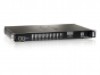
Components Take a moment to familiarize you with the IPS-0008 front and rear panels. The following sections provide descriptions about the front and rear panel components and how to use them. 1.3.1. Front Panel Component 1 Output power status indicator (A ~ H) Description Displays output current - LevelOne IPS-0008 | Manual - Page 9
button Description Enables you to reset the IPS-0008 in case the system locks up. 6 Operation mode DIP switch Sets the mode of operation for the IPS-0008. S1 off, S2 off: Normal operation (default mode) 7 Serial (CONSOLE) port Enables you to configure the IPS-0008 using the serial port. You can - LevelOne IPS-0008 | Manual - Page 10
IPS-0008 has several LED indicators that provide information about the input and output power status. The following table describes these status indicators. Status Indicator Description Output power manual control of each power outlet. Press repeatedly to switch between remote control and power - LevelOne IPS-0008 | Manual - Page 11
the output devices connected to the IPS-0008 outlets. The power consumption is displayed as a percentage value. Input power status indicator Displays input voltage (Volts), input current (Ampere), and frequency (Hz), sequentially on the 7-segment switching display. This indicator also shows system - LevelOne IPS-0008 | Manual - Page 12
as well as turn power on/off for each outlet manually. The control button has two modes of operation. Press the button repeatedly to switch between Remote Control mode and Power On/Off mode. When you press the control button, the IPS-0008 switches modes as follows: After switching modes, you need to - LevelOne IPS-0008 | Manual - Page 13
press control button again within 5 seconds and hold for more than 5 seconds. The outlet power indicator starts flashing green at a faster speed and then inverts its original state. For instance, if outlet power indicator is off (grey) before you press the control button, it turns on (green) after - LevelOne IPS-0008 | Manual - Page 14
excessive current flow to protect the system. Connect a device to each power outlet to sup- ply power to it. Connect dry contact UPS that can be remotely managed through network card. This is currently not supported by the IPS-0008. Connect up to digital outputs that are normally open or normally - LevelOne IPS-0008 | Manual - Page 15
section provides information about setting up the IPS-0008, connecting power, and connecting devices to it before you start using it for power management. Read this section carefully to learn how to connect various devices to it. 2.1. Attaching the feet The IPS-0008 comes with four feet or spacers - LevelOne IPS-0008 | Manual - Page 16
tool for connecting devices to it and controlling their power on/off status through its user interface. The IPS-0008 can be attached to eight output devices whose power status can be controlled remotely and manually. It also supports an EMD (Environmental Monitored Device) or sensors for detecting - LevelOne IPS-0008 | Manual - Page 17
web interface to configure the IPS-0008 parameters. 4. After connecting to WAN, open a browser from a PC in the network and use the IPS-0008 IP address specified through the console menu to open the web interface for system configuration. The following sections provide instructions about how to make - LevelOne IPS-0008 | Manual - Page 18
2.4. Connecting Input Power The IPS-0008 has an IEC C20 power inlet for supplying and managing power for the output devices. Connect the power cord to the power inlet and plug the other end into a power outlet as shown: 14 - LevelOne IPS-0008 | Manual - Page 19
of the devices to each of the power outlets A through H with the power cords supplied with the devices as shown: 2.6. Connecting digital outputs The IPS-0008 provides two digital outputs to which you can connect switches, indicators, or other output devices that are normally open or normally - LevelOne IPS-0008 | Manual - Page 20
device that is connected to sensors for detecting temperature, humidity, water level, and so on can be connected to the IPS-0008 with the console port. The EMD can also be connected to alarms or indicators and controlled through the IPS-0008. Connect the EMD to the console port as shown: Note: The - LevelOne IPS-0008 | Manual - Page 21
Console You can control the output devices and manage their power status through a console or serial connection with your PC. Use the serial cable provided in your package to connect the COM port of your PC and the CONSOLE port of the IPS-0008 as shown. Refer to "Using the console menu" on - LevelOne IPS-0008 | Manual - Page 22
an RJ-45 LAN connection that enables you to monitor and manage the power outlets and digital outputs over the network. The IPS-0008 has a graphic user interface that allows you to control the device through a web browser. Connect the IPS-0008 to a free port on your router using an Ethernet cable as - LevelOne IPS-0008 | Manual - Page 23
is a console application in Windows that enables you to con- figure or control a device through command line parameters. You can con- figure the IPS-0008 parameters and its outlets through simple numerical commands from your keyboard. You can also use Telnet or any other con- sole application for - LevelOne IPS-0008 | Manual - Page 24
box, select the COM port that you have connected to the IPS-0008. Click OK when done. 4. The Properties window opens. Click Restore field is set to 9600. Click OK when done. 5. Press any key. The IPS-0008 Configuration Utility Main menu opens and you are prompted for a pass- word. Type the default - LevelOne IPS-0008 | Manual - Page 25
The main menu options are displayed. 21 - LevelOne IPS-0008 | Manual - Page 26
a submenu, type the number corresponding to the submenu and press Enter. For example, to select the IPS-0008 Configuration menu, type 1 and press Enter. Submenus may have further nested menus which can also be accessed save the changes. ƒ Type 0 (zero) to return to a previous or higher-level menu. 22 - LevelOne IPS-0008 | Manual - Page 27
under the control group submenu to enable input phase detection which allows the IPS-0008 to turn off outlet power if there is a phase mismatch. ƒ Outlets Control: This enables you to control all power outlets and configure each outlet's name, location, and other parameters. ƒ Access Control Table - LevelOne IPS-0008 | Manual - Page 28
through the console menu" on page 18, navigate to the System Group under the IPS-0008 Configuration menu. 2. Select the IP Address item and set the IP address. This address lets you access the IPS-0008 in a TCP/IP network (LAN/WAN). Con- tact your system administrator for assistance if you are not - LevelOne IPS-0008 | Manual - Page 29
, it's output devices remotely from your desktop, laptop, PDA, or even your mobile phone. This section provides instructions about how to use the web interface to configure and control the IPS-0008 remotely. 4.1. Overview Start a web browser such as Internet Explorer from your host PC or laptop and - LevelOne IPS-0008 | Manual - Page 30
. ƒ The front panel displayed in the right pane shows the status of the out- lets, input power, and input current. Click anywhere on the front panel to see detailed information about the IPS-0008 input and output status. Notes: ƒ Each menu page provides online help to assist you in configuring the - LevelOne IPS-0008 | Manual - Page 31
System to view and modify the system date and time. This menu page displays the current IPS-0008 date and time. Select one of the options to configure the date and time by setting it manually, synchronizing with a computer's time, or synchronizing it with an NTP server. Note: When you change the - LevelOne IPS-0008 | Manual - Page 32
Multi-User under System to create a list of users who can access and control the IPS-0008. You can add users who can only view the IPS-0008 status or users who can change the outlet status of the IPS-0008. Click Add New to add a new user to the list and specify the user name - LevelOne IPS-0008 | Manual - Page 33
4.2.3. Changing Event Alert Settings The IPS-0008 sends email or SNMP trap alerts to specified users or workstations who will be alerted with an SNMP trap message. Use this menu page to specify the IP addresses of up to 8 trap receivers, community information, type of trap, severity of trap, and description - LevelOne IPS-0008 | Manual - Page 34
Click Email Notification under Sys- tem to set up a list of up to 8 users who will be alerted with an email. Use this menu to specify the mail server, user account, DNS, and other information necessary to set up a mail server for sending mail alerts. Use the Email Receivers Table to add the Email - LevelOne IPS-0008 | Manual - Page 35
what action is taken by the IPS-0008 when the inlet voltage is not within limits. You can set which power outlets and digital outputs are to Power Status of Outlet: Configure the parameters to identify the out- let, specify its power on/off delay, and output current threshold. You can also manually - LevelOne IPS-0008 | Manual - Page 36
Management to see a list of schedules for turning power outlets on or off as desired. For instance, you may want to turn on all the servers and the administrator's workstation every Monday morning. The - LevelOne IPS-0008 | Manual - Page 37
to see the status of the EMD connected to the IPS-0008. The menu page displays the temperature and humidity of the alarms. 4.3.4. Configuration Click Configuration under Environment to configure the EMD connected to the IPS-0008. This menu enables you to set up the sensor names, high and low set - LevelOne IPS-0008 | Manual - Page 38
34 - LevelOne IPS-0008 | Manual - Page 39
restart the crash device for each of the eight outlet with Power Cycle button. This function will be worked when the status of outlet is power on. So, it connects to Power On/Off button of the Manual Control. If the outlet was power off (The button is gray) then it'll not displayed in - LevelOne IPS-0008 | Manual - Page 40
Appendix Specifications Power Input/Output 110V model ƒ AC Input: IEC C20 inlet, 15 Amp, 100 ~ 125VAC, 50/60Hz ƒ AC Output: NEMA 5-15R outlet, 15 Amp, 100 ~ 125 VAC, - LevelOne IPS-0008 | Manual - Page 41
input power status indicator on the front panel with the error code and a message is displayed in a pop-window from your browser. The log is updated with information about this event. To prevent this condition from occur- ring, select the Control Group submenu under the IPS-0008 Configuration Menu - LevelOne IPS-0008 | Manual - Page 42
and used in accordance with the instructions, may cause harmful interference to radio is encouraged to try to correct the interference by one or more of the following measures: ƒ Reorient for help. WARNING! The use of a shielded-type power cord is required in order to meet FCC emission - LevelOne IPS-0008 | Manual - Page 43
39
-
 1
1 -
 2
2 -
 3
3 -
 4
4 -
 5
5 -
 6
6 -
 7
7 -
8
-
9
-
10
-
11
-
12
-
13
-
14
-
15
-
16
-
17
-
18
-
19
-
20
-
21
-
22
-
23
-
24
-
25
-
26
-
27
-
28
-
29
-
30
-
31
-
32
-
33
-
34
-
35
-
36
-
37
-
38
-
39
-
40
-
41
-
42
-
43
 |
 |

IPS-0008
IP Power Switch
User Manual
Ver 1.0.1-0710
1