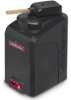
LiftMaster CSW24U CSW24U Wiring Diagram Manual
LiftMaster CSW24U Manual
 |
View all LiftMaster CSW24U manuals
Add to My Manuals
Save this manual to your list of manuals |
LiftMaster CSW24U manual content summary:
- LiftMaster CSW24U | CSW24U Wiring Diagram Manual - Page 1
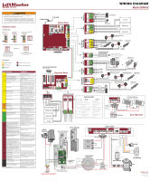
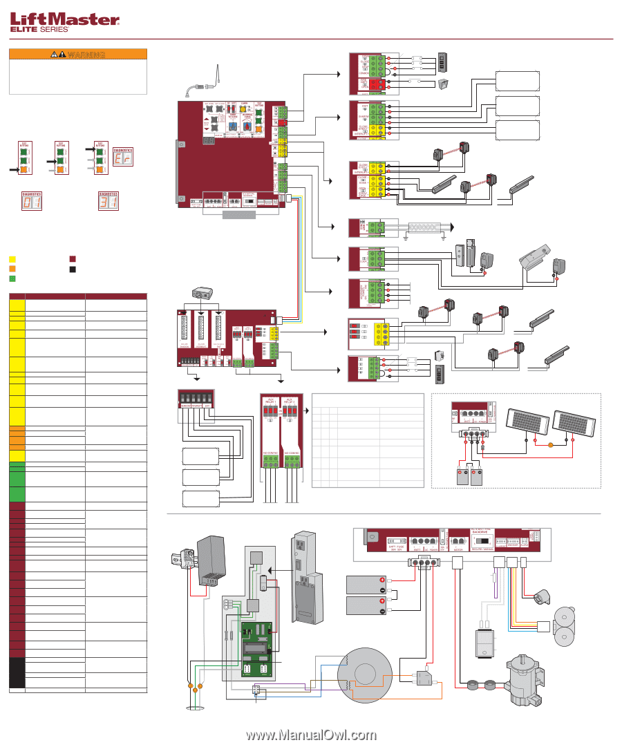
as photoelectric sensors or edge sensors are required to be installed with this operator at each entrapment zone. • See manual regarding maintenance and required safety testing prior to servicing. Diagnostic Codes TO VIEW THE CODES: Press and hold STOP... ...then press and hold CLOSE... ...then - LiftMaster CSW24U | CSW24U Wiring Diagram Manual - Page 2
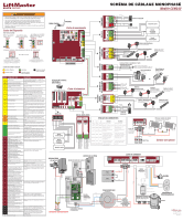
BLAGE MONOPHASÉ Modèle CSW24U Liaison N.F. Poste de commande Service d'incendie Boucle de sortie code « 20 ». NUMÉRO DE CODE Le deuxième numéro montré après le numéro de séquence est le code lui-même (31-99, par exemple « 31 »). LÉGENDE DES CODES DE COULEUR : Système LiftMaster Système install
-
 1
1 -
 2
2
 |
 |
DIAGNOSTICS
+
-
--
SBC
OPN
CLS
STP
COM
EYE
ONLY
EYE/
EDGE
EYE/
EDGE
COM
1
2
3
OPEN
CLOSE
TO MAIN
BOARD
POWER
EYE
ONLY
EYE/
EDGE
EYE/
EDGE
COM
1
2
3
OPEN
CLOSE
SBC
OPN
CLS
STP
COM
C
10W 12V
APS ENCODER
Black
Red
BRIDGE
RECTIFIER
Orange
Black
Red
Black
Red
Orange
ALARM
HEATER
(Optional)
Power Wiring Connector
Power Wiring
Sockets
(120 Vac factory
default)
EMI
BOARD
(Back of Outlet Housing)
Input Power Connection
TRANSFORMER
Battery
12V 7AH
Battery
12V 7AH
Gray
Blue
Brown
Purple
Black
White
Outlet
Outlet
AC Power
Switch
HOT
NEUTRAL
GROUND
Black
White
Green
Black
White
OUTLET HOUSING
AUXILIARY RELAYS
LOOPS
Shadow Loop
Exit Loop
Interrupt Loop
Normally Open
Common
Normally Closed
Normally Open
Common
Normally Closed
Control Stations
SWITCH SETTINGS
1
2
3
RELAY 1
RELAY 2
OFF
Relay always off
Relay always off
OFF
OFF
OFF
OFF
ON
Energizes at open limit
Energizes at open limit
OFF
OFF
ON
Energizes when not at
close limit
Energizes when not at
close limit
OFF
ON
ON
Energizes when motor is on
Energizes when motor is on
ON
OFF
OFF
Energizes 3 seconds prior
and during gate motion
Energizes 3 seconds prior
and during gate motion
ON
OFF
ON
Energizes with AC or
solar power
Energizes with battery
power
ON
OFF
OFF
Energizes when gate is
tampered with
Energizes when gate is
tampered with
ON
ON
ON
LEDs will blink cycle count
Not used
Solar (Optional)
33AH Batteries
J15 Plug
on 33AH Battery
Harness
(K94-37236)
Diode
Jumper
N.C.
CONTROLS
LOCKS
ACCESSORY
POWER
DUAL GATES
ENTRAPMENT
PROTECTION
Primary/Secondary link
to other gate operator
Shielded Twisted Pair Cable
Ground the shield of the cable to the
chassis ground of each operator.
OR
24 Vdc
switched
OR
OR
Maglock
(Optional)
(not provided)
Solenoid Lock
(Optional)
(not provided)
24 Vdc
always on
Photoelectric Sensors
for open or close cycle
Photoelectric Sensor
for open or close cycle
Edge Sensor
for open or close
cycle
Edge Sensor
for open or close
cycle
Photoelectric Sensor
for open or close cycle
Expansion Board
(see below)
PLUG-IN LOOP DETECTOR
Model LOOPDETLM
Control Board
COAXIAL CABLE
ANTENNA
Control Station
Photoelectric Sensors
for close cycle
Edge Sensor
for close cycle
OR
Edge Sensor
for open cycle
Photoelectric Sensors
for open cycle
ENTRAPMENT
PROTECTION
LOOPS
Shadow Loop
Exit Loop
Interrupt Loop
Fire
Department
CONTROLS
Jumper
N.C.
CONTROL BOARD
J15 Plug
Solar Panels (Optional)
20W minimum - 60W maximum,
wired in series
White
White
Black
Purple
Red
Run
Stop/Reset
RESET SWITCH
To Pin 1
To Pin 2
Ferrite EMI Filters
Motor
PRODUCT ID
LiftMaster.com
© 2015, LiftMaster
All Rights Reserved
01-37913-7
WIRING DIAGRAM
Model CSW24U
Press and hold
STOP...
...then press and
hold CLOSE...
...then press and hold OPEN
until "Er" shows.
CODE SEQUENCE NUMBER
The first number shown is the most
recent code (example: “01”). The
display will show the sequence of
codes that occurred starting with “01”
and going up to code “20”.
CODE NUMBER
The second number shown after the code
sequence number is the code itself
(31-99, example” “31”).
A SECOND LATER
....
The operator will show the code sequence number followed by the code number:
Diagnostic Codes
TO VIEW THE CODES:
LiftMaster System
Installed System
Informational
External Entrapment Protection
Inherent Entrapment Protection
CODE
MEANING
SOLUTION
31
Main control board has experienced an internal
failure.
Disconnect all power, wait 15 seconds, then
reconnect power (reboot). If issue continues,
replace main control board.
32
Linear Drive Disengaged (Arm 1)
Disengage then re-engage arm. Check wiring and
connections.
33
Linear Drive Disengaged (Arm 2)
34
Absolute Position Encoder Error, not getting
position information from encoder
Check the operator cable connections, then
reprogram the limits.
35
Max-Run-Time Exceeded Error
Check for an obstruction, then reprogram the
limits.
36
Product ID Error
Was the control board just replaced? If so, erase
limits, enter limit setup mode and set limits. If
not, disconnect all power, wait 15 seconds, then
reconnect power before changing product ID
harness.
37
Product ID Failure
Unplug product ID harness then plug back in.
Disconnect all power, wait 15 seconds, then
reconnect power before replacing product ID
harness.
38
Hard Stop Limit (Arm 1)
Limit may be set too tightly against a non-
resilient hard stop (re-adjust limit). Operator may
be at end of travel (re-adjust mounting).
39
Hard Stop Limit (Arm 2)
40
Battery overvoltage
Too much voltage on the battery. Check harness.
Make sure there is NOT a 24V battery on a 12V
system.
41
Battery overcurrent
Possible short of the battery charge harness.
Check harness. Make sure you do NOT have a
12V battery on a 24V system.
42
No battery at boot up
Check battery connections and installation.
Replace batteries if depleted to less than 20V on
a 24V system or less than 10V on a 12V system.
Make sure there is NOT a single 12V battery on a
24V system.
43
Exit Loop Error
Failure or missing loop (SHORT or OPEN -
LiftMaster Plug-in Loop Detector only) Check
loop wiring throughout connection. May be a
short in the loop, or an open connection in the
loop.
44
Shadow Loop Error
45
Interrupt Loop Error
46
Wireless edge battery low
Replace batteries in wireless edge.
50
Run-Distance Error
Gate unbalance detected. Make sure the gate is
installed on a level surface and not on an
excessive grade.
51
Pass-point not detected (Arm 1)
Check yellow pass-point wiring. If limits are not
accurate, reprogram.
52
Pass-point not detected (Arm 2)
53
Brownout occurred
AC/DC board supply dipped below allowable
level. Review power supply and wiring. If
rebooting, ensure enough time for discharge of
power to force a fresh boot.
54
Wireless Second Operator Communication Error
Check the second operator for power. If OFF,
restore power and try to run the system. If
powered, deactivate the wireless feature and then
reprogram the second operator.
60
Minimum number of monitored entrapment
protection devices (one) not installed.
Review monitored entrapment protection device
connections.
61
CLOSE EYE/INTERRUPT held more than 3
minutes
Check wired input on main control board; check
for alignment or obstruction.
62
CLOSE EDGE held more than 3 minutes
63
OPEN EYE/EDGE held more than 3 minutes
64
CLOSE EYE/INTERRUPT held more than 3
minutes
Check wired input on expansion board; check for
alignment or obstruction.
65
CLOSE EYE/EDGE held more than 3 minutes
66
OPEN EYE/EDGE held more than 3 minutes
67
Wireless edge triggered more than 3 minutes
Check wired input for wiring issue or
obstruction.
68
Wireless edge loss of monitoring
Check wireless edge inputs.
69
Wireless edge triggered
IF an obstruction occurred, no action required. If
an obstruction did NOT occur, check inputs and
wiring.
70
CLOSE EYE/INTERRUPT triggered, causing
reversal, preventing close, or resetting TTC
IF an obstruction occurred, no action required. If
an obstruction did NOT occur, check alignment,
inputs, and wiring on main control board.
71
CLOSE EDGE triggered, causing reversal,
preventing close, or canceling TTC
72
OPEN EYE/EDGE triggered, causing reversal or
preventing opening
73
CLOSE EYE/INTERRUPT triggered, causing
reversal, preventing close, or resetting TTC
IF an obstruction occurred, no action required. If
an obstruction did NOT occur, check alignment,
inputs, and wiring on expansion board.
74
CLOSE EYE/EDGE triggered, causing reversal
and preventing close or canceling TTC
75
OPEN EYE/EDGE triggered, causing reversal or
preventing opening
80
Close input (EYE/EDGE) communication fault
from other operator
Check inputs and communication method
between operators, either wired bus or radio.
Ensure operator is powered. May have to erase
the wireless communication and reprogram the
two operators.
81
Open input (EYE/EDGE) communication fault
from other operator
82
Close input (EYE/EDGE) communication fault
(expansion board)
Check the connections between the main board
and the expansion board.
83
Open input (EYE/EDGE) communication fault
(expansion board)
91
Force Reversal (Operator 1)
Check for obstruction. If no obstruction, check
that the mechanical assembly is engaged and
free to move. See section on Limit and Force
Adjustment, and Obstruction Test in the manual.
92
Force Reversal (Operator 2)
93
RPM / STALL Reversal (Operator 1)
Check for obstruction. If no obstruction, check
the operator wiring and that the mechanical
assembly is engaged and free to move. Replace
APE assembly.
94
RPM / STALL Reversal (Operator 2)
99
Normal Operation
No action required
WARNING
•
DISCONNECT power and battery BEFORE installing or servicing operator.
•
Replace ONLY with fuse of same type and rating.
•
To be compliant with UL325 and industry safety guidelines, qualified monitored
external entrapment protection devices such as photoelectric sensors or edge
sensors are required to be installed with this operator at each entrapment zone.
•
See manual regarding maintenance and required safety testing prior to servicing.
CODE COLOR KEY: