LiftMaster EL2000 EL25 - INSTALLATION Manual
LiftMaster EL2000 Manual
 |
View all LiftMaster EL2000 manuals
Add to My Manuals
Save this manual to your list of manuals |
LiftMaster EL2000 manual content summary:
- LiftMaster EL2000 | EL25 - INSTALLATION Manual - Page 1
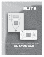
® ® ™ ™ Installation Manual for EL MODELS Telephone entry/access control system © 2008 The Chamberlain Group, Inc. All Rights Reserved - LiftMaster EL2000 | EL25 - INSTALLATION Manual - Page 2
- LiftMaster EL2000 | EL25 - INSTALLATION Manual - Page 3
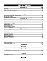
Radio Frequency Module Wiegand Card Reader / Keypad Wiring a Postal Lock Switch Wiring an Internal Camera (CCTV) Power Wiring Power to the Unit Powering up and Checking the LEDs Troubleshooting Repair Parts "Your" System Diagram and Wiring Configuration Repair Parts "Your" Set-Up Accessories FCC - LiftMaster EL2000 | EL25 - INSTALLATION Manual - Page 4
Dimensions EL25 Units 6 in. 3-15/16 in. 3/4 in. Conduit Hole Mounting Holes (4) for 5/16 in. Caution! A Static Discharge can Damage Circuit Boards EL2000 Units Knockouts for 3/8 in. Knockouts for 5/16 in. 9 in. AUG 10, 2005 WELCOME 7 in. 3-1/16 in. 15 in. 9-1/2 in. 3-1/16 in. Dimensions - LiftMaster EL2000 | EL25 - INSTALLATION Manual - Page 5
Cover Up then Slide Out on Hinges 3 Unplug the 2 Main Harnesses EL25 Installation 4 Line up Notch with Screw and Push Hinge Out Screw Notch 5 wire per hole. Rotating the Keypad for Vertical Mounting Caution! A Static Discharge can Damage Circuit Boards For EL25 ONLY 1 Disconnect all Plugs - LiftMaster EL2000 | EL25 - INSTALLATION Manual - Page 6
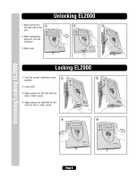
pressure, turn key 456 789 *0 # clockw# ise 3. Open cover 2 # # # 1 23? 456 789 *0 # 3 1 4 2 5 3 6 ? 789 * #0 # # Unlocking/Locking EL2000 Locking EL2000 1. Turn key counter clockwise to lock 1 position # 2 # # 2. Close cover # # # 3. Apply pressure to left-side until you - LiftMaster EL2000 | EL25 - INSTALLATION Manual - Page 7
EL2000 Model Installation EL2000 Installation NOTE: This unit is for surface and recessed mount ONLY. 1 Unlock Unit 2 Open Cover 1 23? 456 789 *0 # # 1 4 2 5 3 6 ? 789 # *0 # 3 Unplug the 2 Main Harnesses (Optional) 4 Slide Front - LiftMaster EL2000 | EL25 - INSTALLATION Manual - Page 8
Wire Connections to the Unit Wire Connections to the Unit IO Output Board EXIT REQ 4 4 COM J7 DOOR STAT 4 EXIT REQ 3 3 COM J6 DOOR STAT 3 EXIT REQ 2 2 COM J5 DOOR STAT 4 EXIT REQ 1 1 COM J4 DOOR STAT 1 POSTAL 5 J3 AUTO 6 J2 J1 7 POWER 12VAC/DC IO Input Board RES 8 J6 - LiftMaster EL2000 | EL25 - INSTALLATION Manual - Page 9
in preparation of your installation: Description of Wire 18 500 feet 18 100 feet 18 19 CCTV Camera (Optional) Single Conductor RG-59u Coaxial 1000 feet problems: • Other equipment cannot introduce spikes, noise, surges or dips into the power circuit that will affect the system. • The system - LiftMaster EL2000 | EL25 - INSTALLATION Manual - Page 10
Units Grounding the Units Ensure that the system is grounded properly. The units contain a by region. Contact the building inspector's office in the municipality where you plan to install the unit for correct grounding materials and installation procedures. 1 3 2 5 4 10 9 11 8 7 6 OR Green - LiftMaster EL2000 | EL25 - INSTALLATION Manual - Page 11
telephone operation. NOTE: Installation where fiber optic phone lines are present may require additional modifications from your telephone the unit will be used in conjunction with an alarm system, you MUST connect the telephone line to the alarm system first. If the units are not connected in this - LiftMaster EL2000 | EL25 - INSTALLATION Manual - Page 12
the unit ID's for each unit wired in the series. See Keypad Programming Manual. Never run Telco wires and High Voltage wires in the same conduit. The high voltage wires may interfere with the Telco wires, possibly causing the system to malfunction. Use 18-24 AWG 2 twisted pair DO NOT overload - LiftMaster EL2000 | EL25 - INSTALLATION Manual - Page 13
wires may interfere with the Telco wires, possibly causing the system to malfunction. NOTE: Ringer Equivalence Number (REN) of "5" Keypad Programming Manual. IMPORTANT: Only disable the Telco mode of the unit farthest away from the house. See "Disable Telco Mode" in the Keypad Programming Guide - LiftMaster EL2000 | EL25 - INSTALLATION Manual - Page 14
: Installation where fiber optic phone lines are present may require additional modifications from your telephone provider Line Multiple Units (Up to 7) IMPORTANT: You must program the Unit ID's for each unit wired in the series. See Keypad Programming Manual. To next unit (Unit ID 5 then 4 etc - LiftMaster EL2000 | EL25 - INSTALLATION Manual - Page 15
system. NOTE: Installation where fiber optic phone lines are present may require additional modifications from your telephone an Internal Phone System Multiple Units (Up to 7) IMPORTANT: You must program the unit ID's for each unit wired in the series. See Keypad Programming Manual. To next unit - LiftMaster EL2000 | EL25 - INSTALLATION Manual - Page 16
NO J3 NC C LED 2 NO RELAY 2 NC J1 C LED 1 RELAY 1 Connection To A NPBI System Multiple Units (Up to 7) IMPORTANT: You must program the Unit ID's for each unit wired in the series. See Keypad Programming Manual. To next unit (Unit ID 5 then 4 etc.) Unit ID 1 is farthest away from Telco Box - LiftMaster EL2000 | EL25 - INSTALLATION Manual - Page 17
RES AC or DC Power for Door Strike (Not Provided) DO NOT use the unit's power supply for the Maglock. Install a 1N4005 diode or equivalent. - + J6 For AC Power: Install a Siemens S10K30 MOV (Metal Oxide VarTisEtoLrC) oOr equivalent. Normally Closed J8 Use 18-22 AWG Common NOTE: The maglock can - LiftMaster EL2000 | EL25 - INSTALLATION Manual - Page 18
J1 Common Use 18-24 AWG NOTE: The gate operator can be connected to any of the 4 relays. NOTE: Refer to your gate operators owner's manual for proper relay strike time. NO LED 4 NC C RELAY 4 NO NC LED 3 C RELAY 3 NO NC C LED 2 NO RELAY 2 NC C LED 1 RELAY 1 Wiring a Key Switch/PIR - LiftMaster EL2000 | EL25 - INSTALLATION Manual - Page 19
record the breach in its transactions and can perform the following actions: • Energize a relay to activate an alarm device such as a siren, light or CCTV camera. • Main use is to terminate strike time early. EXIT REQ 4 COM DOOR STAT 4 EXIT REQ 3 COM DOOR STAT 3 EXIT REQ 2 COM DOOR STAT 4 EXIT REQ - LiftMaster EL2000 | EL25 - INSTALLATION Manual - Page 20
Keypad Wiring a Radio Frequency Module An optional radio frequency module and a remote antenna can be installed if the residents will access a controlled area with a transmitter. Refer to instructions the unit ground only). 1 Wiegand Module Kit Part # WOMODKT Wiegand Modules will fit in J400 as - LiftMaster EL2000 | EL25 - INSTALLATION Manual - Page 21
to instructions supplied with the camera kit for more information. Home Entertainment System A Closed Circuit Monitor Contact your dealer/ installer for more information OR RG-59u Coaxial Cable 1000 Feet Maximum (Monitor with a .25 volt p-p composite signal sensitivity) EL25 EL2000 Page 19 - LiftMaster EL2000 | EL25 - INSTALLATION Manual - Page 22
should be wired back to its own 10 Amp minimum circuit breaker. This will prevent two problems: • Other equipment cannot introduce spikes, noise, surges or dips into the power circuit. • The system's operation will not be affected if any other equipment develops a short circuit across the power line - LiftMaster EL2000 | EL25 - INSTALLATION Manual - Page 23
Input Board LCD PWR EL25=LED BOTTOM KEYPAD EL2000=LED keypad MIC 14-Pin Connector to Output Board KEYPAD Local Mode RES DAA keypad Unit supplying Central Office Power to Resident Resident side of circuit is off hook Telco side of circuit is off hook Used for direct connect and handheld programming - LiftMaster EL2000 | EL25 - INSTALLATION Manual - Page 24
a relay to the REX? See the unit's programming manual. • Check connections at Door # terminal(s). Wires to "COM" and "EXT REQ #" connection. Transmitter not working • Did you use the correct coaxial cable? See page 7. • Is the remote antenna installed correctly? Is it outside of the unit's enclosure - LiftMaster EL2000 | EL25 - INSTALLATION Manual - Page 25
EL25 Parts 4 6 5 1 8 9 Repair Parts Installation and Service Information is Available Call our Toll Free Number 1-800-528-2806 www.chamberlain.com 21 12 2 3 11 22 7 13 10 15 14 19 11 20 17 16 18 Repair Parts When ordering repair parts, please supply the following information: - LiftMaster EL2000 | EL25 - INSTALLATION Manual - Page 26
Button Board EL2000 12 Postal Lock Switch EL2000 Model Number Part Description 41B989 EL2000 15 Replacement Key 16 Assembly, Keypad 16 Button 17 Gasket, Keypad 18 Assembly, Mike Cable EL Series 19 Assembly, Entry LED Board 20 Assembly, Keypad Light Board 21 Lens Black, Camera Lens Clear, Camera - LiftMaster EL2000 | EL25 - INSTALLATION Manual - Page 27
Your System Diagram Your System Diagram Page 25 - LiftMaster EL2000 | EL25 - INSTALLATION Manual - Page 28
2 Connection Door 4 Connection Door Sensor and/or Exit Device Door Sensor and/or Exit Device Postal Yes Lock No AutoCall Yes Device No CCTV Yes Camera No Dealer / Installer Page 26 - LiftMaster EL2000 | EL25 - INSTALLATION Manual - Page 29
Camera) EL2000DVRCAMKT (Low Lux DVR Color Camera) EL2000CAMKT (Color Camera) RF Module Kit RFMODKT (390 MHz) RFMODKT3 (315 MHz) 123 456 789 *0# Wiegand Remote Keypad ESSWOKSG EL2000 EL25 Heater Kit ELHTRKT EL2000 ONLY ? Quick For Single F St EL SERIES rt Guide Service" - LiftMaster EL2000 | EL25 - INSTALLATION Manual - Page 30
to the user's satisfaction. Before installing this equipment, users should ensure that installed using an acceptable method of connection. In some cases, the company's inside wiring associated with single line individual service may be extended by means of a certified connector assemble (telephone - LiftMaster EL2000 | EL25 - INSTALLATION Manual - Page 31
- LiftMaster EL2000 | EL25 - INSTALLATION Manual - Page 32
114A2980F © 2008 The Chamberlain Group, Inc. All Rights Reserved ® ™ 845 Larch Avenue Elmhurst, Illinois 60125-1196
-
 1
1 -
 2
2 -
 3
3 -
 4
4 -
 5
5 -
 6
6 -
 7
7 -
8
-
9
-
10
-
11
-
12
-
13
-
14
-
15
-
16
-
17
-
18
-
19
-
20
-
21
-
22
-
23
-
24
-
25
-
26
-
27
-
28
-
29
-
30
-
31
-
32
 |
 |
Telephone entry/access control system
© 2008 The Chamberlain Group, Inc.
All Rights Reserved
®
™
®
™
Installation Manual for
Installation Manual for
EL MODELS
EL MODELS