LiftMaster GH5HP Owners Manual
LiftMaster GH5HP Manual
 |
View all LiftMaster GH5HP manuals
Add to My Manuals
Save this manual to your list of manuals |
LiftMaster GH5HP manual content summary:
- LiftMaster GH5HP | Owners Manual - Page 1
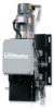
OWNER'S MANUAL MODEL GH 5HP HEAVY DUTY DOOR OPERATOR FACTORY SET C2 Wiring See page 8 for other wiring configurations 2 YEAR WARRANTY Serial # (located on electrical box cover) Installation Date Wiring Type - LiftMaster GH5HP | Owners Manual - Page 2
. DISCONNECT Floor level chain hoist with electrical interlock for emergency manual door operation. ELECTRICAL TRANSFORMER 3PH: 208/230/480 VAC 24VAC OR 3PH: 575VAC-24VAC CONTROL STATION: ........NEMA 1 three button station. OPEN/CLOSE/STOP WIRING TYPE Standard C2 Wiring- Standard operators are - LiftMaster GH5HP | Owners Manual - Page 3
LOCKS INOPERATIVE. SECURE LOCK(S) IN "OPEN" POSITION. IF THE DOOR LOCK NEEDS TO REMAIN FUNCTIONAL, INSTALL AN INTERLOCK SWITCH. DO NOT CONNECT ELECTRIC POWER UNTIL INSTRUCTED TO DO SO. KEEP DOOR BALANCED. STICKING OR BINDING DOORS MUST BE REPAIRED. DOORS, DOOR SPRINGS, CABLES, PULLEYS, BRACKETS AND - LiftMaster GH5HP | Owners Manual - Page 4
instructions below that suits your application. NOTE: The operator has a weight of 300 lbs. 1a. Wall Mounting The operator should generally be installed below the door shaft, and as close to the door bracket must provide adequate support, prevent play between operator and door shaft, and permit - LiftMaster GH5HP | Owners Manual - Page 5
hand chain wheel. Be sure to pass it through both openings in the chain guide. Remove enough links so chain hangs approximately two feet above COLLAR 12-14737 Engaged Position EMERGENCY MANUAL OPERATION This operator has provisions for manually operating the door in case of emergency or power - LiftMaster GH5HP | Owners Manual - Page 6
MANUALLY MOVING LIMIT NUTS. 3. Adjust open limit nut so that door will stop in open position with the bottom of the door even with top of door opening. 4. Repeat Steps 1 and 2 for close cycle. Adjust close limit nut so that actuator is engaged as door fully seats at the floor. If other problems - LiftMaster GH5HP | Owners Manual - Page 7
. If this diagram is missing, call the number on the back of this manual. DO NOT INSTALL ANY WIRING OR ATTEMPT TO RUN THIS OPERATOR WITHOUT CONSULTING THE TO AVOID DAMAGE TO DOOR AND OPERATOR, MAKE ALL DOOR LOCKS INOPERATIVE. SECURE LOCK(S) IN "OPEN" POSITION. IF THE DOOR LOCK NEEDS TO REMAIN - LiftMaster GH5HP | Owners Manual - Page 8
-standard control wiring or with optional accessories that require addition instructions, refer to the wiring diagram(s) indicated in the special control wiring data box. When a replacement wiring diagram is present, wiring diagrams in this manual will not apply. Refer only to the replacement wiring - LiftMaster GH5HP | Owners Manual - Page 9
/STOP) is recommended. SOME TYPE OF ENTRAPMENT PROTECTION DEVICE. THE USE OF RADIO CONTROLS PRESENTS POTENTIAL HAZARDS DUE TO THE USER'S ABILITY TO OPEN OR CLOSE THE DOOR WHEN OUT OF SIGHT OF THE DOOR. IN CAUTION ADDITION, IF A SINGLE CHANNEL CONTROL IS USED, THE USER WILL NOT BE ABLE TO STOP THE - LiftMaster GH5HP | Owners Manual - Page 10
BENEATH THE DOOR. The operator has been pre-wired to accept WARNING connection of a reversing edge device. Connect the normally open contacts to terminals BEFORE SERVICING OR ADJUSTING THE OPERATOR. Be sure you have read and understand all Safety Instructions included in this manual. CAUTION - LiftMaster GH5HP | Owners Manual - Page 11
in the following chart. ITEM Drive Chain Sprockets Fasteners Manual Disconnect Bearings & Shafts PROCEDURE Check for excessive slack. SUPPLY. WARNING WARNING HOW TO ORDER REPAIR PARTS OUR LARGE SERVICE ORGANIZATION SPANS AMERICA INSTALLATION AND SERVICE INFORMATION ARE AVAILABLE 6 DAYS A WEEK - LiftMaster GH5HP | Owners Manual - Page 12
1942 THREE PHASE SCHEMATIC DIAGRAM 12 - LiftMaster GH5HP | Owners Manual - Page 13
THREE PHASE FIELD WIRING 1942 13 - LiftMaster GH5HP | Owners Manual - Page 14
requirements. Optional modifications and/or accessories included with your operator may add or remove certain components from these lists. Please consult a parts and service representative regarding availability of individual components of kits specified below. Refer to page 11 for all repair - LiftMaster GH5HP | Owners Manual - Page 15
ILLUSTRATED PARTS - ELECTRICAL BOX WARNING WARNING 15 - LiftMaster GH5HP | Owners Manual - Page 16
parts and service representative regarding availability of individual components. Refer to page 11 for all repair part ordering information. INDIVIDUAL PARTS ITEM PART C1 C2 C3 C4 C5 PART # 10-10882 12-10883 75-10884 80-10022 87-E-075 DESCRIPTION Hand Chain Guide Nyliner Bearing Chain Wheel - LiftMaster GH5HP | Owners Manual - Page 17
ILLUSTRATED PARTS - MODEL GH 5HP 17 - LiftMaster GH5HP | Owners Manual - Page 18
OPERATOR NOTES 18 - LiftMaster GH5HP | Owners Manual - Page 19
OPERATOR NOTES 19 - LiftMaster GH5HP | Owners Manual - Page 20
or 3 POSITION KEYSWITCH w/ SPRING RETURN TO CENTER AND STOP BUTTON STANDARD 1234 2 OR MORE 1234 KEY LOCKOUT 1234 Open Close Stop Open Close Stop Open Close Stop Open Close Stop Keyswitch ALL CONTROL WIRING TYPES ALL CONTROL WIRING TYPES 2 BUTTON STATION or 3 POSITION KEYSWITCH w/ SPRING
-
 1
1 -
 2
2 -
 3
3 -
 4
4 -
 5
5 -
 6
6 -
 7
7 -
8
-
9
-
10
-
11
-
12
-
13
-
14
-
15
-
16
-
17
-
18
-
19
-
20
 |
 |

OWNER'S MANUAL
MODEL GH 5HP
HEAVY DUTY DOOR OPERATOR
Serial #
(located on electrical box cover)
Installation Date
Wiring Type
2
YEAR
WARRANTY
C2 Wiring
FACTORY SET
See page 8 for
other wiring
configurations