LiftMaster H J (CUBE STYLE) Manual
LiftMaster H Manual
 |
View all LiftMaster H manuals
Add to My Manuals
Save this manual to your list of manuals |
LiftMaster H manual content summary:
- LiftMaster H | J (CUBE STYLE) Manual - Page 1
'S MANUAL MODELS: J H HJ INDUSTRIAL DUTY DOOR OPERATOR NEW! Cube Style Electrical Box FACTORY SET C2 Wiring See page 8 for other wiring configurations 2 YEAR WARRANTY Serial # (located on electrical box cover) Installation Date Wiring Type NOT FOR RESIDENTIAL USE 41B6 LISTED DOOR OPERATOR - LiftMaster H | J (CUBE STYLE) Manual - Page 2
OR ANY OTHER CONTROL (AUTOMATIC OR MANUAL) IS USED. WEIGHTS AND DIMENSIONS HANGING WEIGHT: .........80-110 LBS. 14.44" 7.27" 7.17" 2.00" 17.63" 14.60" MOUNTING DIMENSIONS A - Wall Mounting B - Bracket Mounting (rolling door) 4.63" 3/8" BOLT 7.56" 4.41" 6.59" A B 5.50" B 1.50" A B 13.75 - LiftMaster H | J (CUBE STYLE) Manual - Page 3
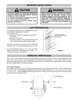
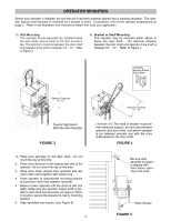
the wall or mounting surface provide adequate support for the operator. This surface must: a) Be rigid to prevent play between operator and door shaft. b) Provide a level base. c) Permit the operator to be fastened securely and with the drive shaft parallel to the door shaft. Shaft Support Bracket - LiftMaster H | J (CUBE STYLE) Manual - Page 4
Optimum Distance 12 - 15" Optimum Distance 12 - 15" Typical Right Hand Wall Mounted Operator FIGURE 3 IMPORTANT: The shelf or bracket must provide adequate support, prevent play between operator and door shaft, and permit operator to be fastened securely and with the drive shaft parallel to the - LiftMaster H | J (CUBE STYLE) Manual - Page 5
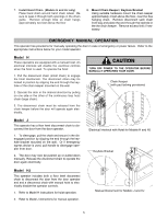
HJ Keyhole Bracket Model HJ This operator includes both a floor level disconnect chain to disconnect the door from the door operator and and a disconnect chain with manual hoist to electrically disable the operator controls. 1. Refer to Model H instructions for hoist operation. 2. Refer to Model - LiftMaster H | J (CUBE STYLE) Manual - Page 6
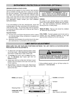
end of coil cord to junction box (not supplied) fastened to the wall approximately halfway up the door opening. b) Electrician must hardwire the junction box to the operator electrical box in accordance with local codes. LIMIT SWITCH ADJUSTMENT MAKE SURE THE LIMIT NUTS ARE POSITIONED BETWEEN THE - LiftMaster H | J (CUBE STYLE) Manual - Page 7
UNTIL YOU HAVE FINISHED MAKING ALL POWER AND CONTROL WIRING CONNECTIONS AND HAVE COMPLETED WARNING THE LIMIT SWITCH ADJUSTMENT PROCEDURE. TO AVOID DAMAGE TO DOOR AND OPERATOR, MAKE ALL DOOR LOCKS INOPERATIVE. SECURE LOCK(S) IN "OPEN" POSITION. IF THE DOOR LOCK NEEDS TO REMAIN FUNCTIONAL, INSTALL AN - LiftMaster H | J (CUBE STYLE) Manual - Page 8
All operators are supplied with some type of control station. Generally a three button station (OPEN/CLOSE/STOP) is provided. A two-position key switch or control station (OPEN/CLOSE) may be added or substituted when requested at the time of order. Mount the control station near the door. WARNING - LiftMaster H | J (CUBE STYLE) Manual - Page 9
On all models with type B2 control wiring, a terminal bracket marked R1 R2 R3 is located on the outside of the electrical enclosure. All standard radio control receivers (single channel residential type) may be mounted to this bracket. The operator will then open a fully closed door, close a fully - LiftMaster H | J (CUBE STYLE) Manual - Page 10
SERVICING OR ADJUSTING THE OPERATOR. Be sure you have read and understand all Safety Instructions included in this manual. CAUTION Be sure the owner or person(s) responsible for operation of the door have read and understand the Safety Instructions, know how to electrically operate the door - LiftMaster H | J (CUBE STYLE) Manual - Page 11
Fasteners Manual Disconnect tension Check & tighten as required Check & Operate Check for wear & lubricate EVERY 3 MONTHS operation. n Do not lubricate clutch or V-belt. n Inspect and service whenever a malfunction is observed or suspected. n CAUTION: BEFORE SERVICING, ALWAYS DISCONNECT OPERATOR - LiftMaster H | J (CUBE STYLE) Manual - Page 12
#1) (BK) 230V MODELS 115V MODELS PUR BL YEL GY BL/BK 1 8 5 23 4 BL/BK 230 VOLT - 1 PHASE MOTOR CONNECTION CL 4 3 OP 4 3 OP 2 1 CL 6 5 OP 5 6 CL 1 2 (YE) (BL) (PUR) TO MOTOR (GY) 3 (YEL) STOP OPEN (OR) SAFETY EDGE R1 (OR) (BR) EXTERNAL 4 INTERLOCK HAND CHAIN INTL - LiftMaster H | J (CUBE STYLE) Manual - Page 13
MUST BE REMOVED FOR 23OV 1PH OPERATION. **- Transformer Primary & Relay Voltage same as Line Voltage. 1 2 3 4 5 7 10 L1 L2 L3 OPEN CLOSE STOP EXT. INTLK. TO OPEN AND CLOSE SAFETY EDGE L1 L2 **1 PHASE POWER IN GROUND * - Shipped from Factory CLOSE CONTROL WIRING OPTIONS * C2 WIRING: Constant - LiftMaster H | J (CUBE STYLE) Manual - Page 14
YEL) HAND CHAIN YEL) OPEN (OR CONTROL WIRING OPTIONS *C2 WIRING - Constant Presssure to Close RED WIRE ON TERMINAL #2 (Shipped from Factory) B2 WIRING - Momentary Contact to Close MOVE RED WIRE FROM TERMINAL #2 TO TERMINAL #3 NOTE: 1. Voltage same as line voltage 2. Overload in motor for models - LiftMaster H | J (CUBE STYLE) Manual - Page 15
SWITCHES PURPLE NC CLOSE C L/S PURPLE BLACK BROWN LOAD 24VAC YELLOW BLACK XFMR **LINE WIRE NUT ( 3/4 HP & BELOW) R1 RELAY ( 3/4 HP & GROUND OPEN CLOSE STOP NOTES: EXT. INTLK. TO OPEN AND CLOSE SAFETY EDGE L1 L2 L3 **3 PHASE POWER IN * - Shipped from Factory CLOSE CONTROL WIRING - LiftMaster H | J (CUBE STYLE) Manual - Page 16
ELECTRICAL BOX - ILLUSTRATED PARTS S2 S1 S6 S5 S3 S7 S8 S4 L3 S9 L1 10 5 L5 L8 3 L6 L2 1 2 11 9 L7 5 4 8 L2 L6 L4 7 6 16 - LiftMaster H | J (CUBE STYLE) Manual - Page 17
service representative regarding availability of individual components of kits specified below. Refer to page11 for all repair part ordering information. Complete Electrical Box Replacement Kits To order a complete electrical box replacement kit, add a K- prefix to the model number of your operator - LiftMaster H | J (CUBE STYLE) Manual - Page 18
ILLUSTRATED PARTS - Model J 5 6 7 1 8 9 C8 C20 C10 C9 D1 D7 D4 D8 D11 D3 D10 D9 D2 D5 D6 C4 C21 C6 C16 C24 C7 C17 C14 C18 C3 - LiftMaster H | J (CUBE STYLE) Manual - Page 19
External Snap Ring, Zinc Coated 2 K75-12558 RIGHT HAND DISCONNECT ASSY KIT ITEM PART # DESCRIPTION QTY D1 10-10707 Disconnect Support Bracket 1 D2 10-10708 Yoke 1 D3 10-10875 Disconnect Lever 1 D4 10-10898 Interlock Switch Actuator 1 D5 11-10878 Disconnect Shaft 1 D6 19-8A-12 12 ft - LiftMaster H | J (CUBE STYLE) Manual - Page 20
ILLUSTRATED PARTS - Model H 5 6 D1 D7 D4 D8 D11 D3 C12 1 D10 D9 D2 D5 D6 C15 C6 C2 C17 C5 C7 C19 C16 C18 C4 C25 C18 C19 - LiftMaster H | J (CUBE STYLE) Manual - Page 21
87-P-100S Push Ring 1" Plated 4 K75-12558 RIGHT HAND DISCONNECT ASSY KIT ITEM PART # DESCRIPTION QTY D1 10-10707 Disconnect Support Bracket 1 D2 10-10708 Yoke 1 D3 10-10875 Disconnect Lever 1 D4 10-10898 Interlock Switch Actuator 1 D5 11-10878 Disconnect Shaft 1 D6 19-8A-12 12 ft - LiftMaster H | J (CUBE STYLE) Manual - Page 22
ILLUSTRATED PARTS - MODEL HJ 22 8 5 6 1 7 L1 L7 L4 L10 L9 L8 L11 L3 C17 L2 L5 L6 C7 C2 C20 C6 C5 C22 C23 C30 C14 C19 O10 O5 - LiftMaster H | J (CUBE STYLE) Manual - Page 23
O11 87-P-100S Push on Fastener 4 K75-12558 RIGHT HAND DISCONNECT ASSY KIT ITEM PART # DESCRIPTION QTY R1 10-10707 Disconnect Support Bracket 1 R2 10-10708 Yoke 1 R3 10-10875 Disconnect Lever 1 R4 10-10898 Interlock Switch Actuator 1 R5 11-10878 Disconnect Shaft 1 R6 19-8A-12 12 ft - LiftMaster H | J (CUBE STYLE) Manual - Page 24
R2 R3 EXTERNAL TERMINAL BLOCK Sensing Device RADIO CONTROL ALL CONTROL WIRING TYPES TIMER TO CLOSE w/ WARNING LIGHT ALL CONTROL WIRING TYPES * T1 WIRING - RADIO TO OPEN ONLY EXTERNAL INTERLOCK Warning Light will activate 15 sec. before door closes. 11 12 13 14 Auxiliary Terminal Block Remove
-
 1
1 -
 2
2 -
 3
3 -
 4
4 -
 5
5 -
 6
6 -
 7
7 -
8
-
9
-
10
-
11
-
12
-
13
-
14
-
15
-
16
-
17
-
18
-
19
-
20
-
21
-
22
-
23
-
24
 |
 |

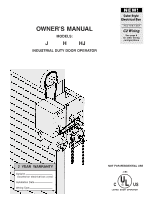
OWNER'S MANUAL
MODELS:
J
H HJ
INDUSTRIAL DUTY DOOR OPERATOR
Serial #
(located on electrical box cover)
Installation Date
Wiring Type
2 YEAR WARRANTY
C2 Wiring
FACTORY SET
See page 8
for other wiring
configurations
Cube Style
Electrical Box
NEW!
NOT FOR RESIDENTIAL USE
LISTED
DOOR
OPERATOR
41B6