LiftMaster J J LOGIC VERSION 1 Manual
LiftMaster J Manual
 |
View all LiftMaster J manuals
Add to My Manuals
Save this manual to your list of manuals |
LiftMaster J manual content summary:
- LiftMaster J | J LOGIC VERSION 1 Manual - Page 1
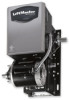
'S MANUAL MODELS: J 3 H 3 HJ SOLID STATE INDUSTRIAL DUTY DOOR OPERATOR LOGIC LCONTROL FACTORY SET C2 Wiring See pages 13 & 14 for other wiring configurations 2 YEAR WARRANTY Serial # (located on electrical box cover) Installation Date Wiring Type NOT FOR RESIDENTIAL USE 41B6 LISTED DOOR OPERATOR - LiftMaster J | J LOGIC VERSION 1 Manual - Page 2
emergency manual door operation. Model HJ: Includes both floor level disconnect systems stated above. REVERSING EDGE:......(Optional) Electric or pneumatic sensing device attached to the bottom edge of door. A REVERSING EDGE IS STRONGLY RECOMMENDED FOR ALL COMMERCIAL OPERATOR INSTALLATIONS. REQUIRED - LiftMaster J | J LOGIC VERSION 1 Manual - Page 3
manual hoist hand chain systems, the handing of the operator must be determined at the time of order. The handing is indicated by last letter of the model name (R or L). The hand chain wheel can not be switched on site. If your installation causes the hand chain to hang in the door opening, hook - LiftMaster J | J LOGIC VERSION 1 Manual - Page 4
on page 3. Refer to the illustration and instructions below that suits your application. 1a. Wall Mounting The operator should generally be installed below the door shaft, and as close to the door as possible. The optimum distance between the door shaft and operator drive shaft is between 12" - 15 - LiftMaster J | J LOGIC VERSION 1 Manual - Page 5
links if necessary. EMERGENCY MANUAL OPERATION This operator has provisions for manually operating the door in case of emergency or power failure. Refer to the appropriate instructions below for your model operator. Model H These operators are equipped with a manual hoist. An electrical interlock - LiftMaster J | J LOGIC VERSION 1 Manual - Page 6
BE USED IN CONJUNCTION WITH THIS OPERATOR. TAKE-UP REEL: Take-up reel should be installed 12" above the top of the door. COIL CORD: Connect operator end of coil cord to junction box (not supplied) fastened to the wall approximately halfway up the door opening. LIMIT SWITCH ADJUSTMENT MAKE SURE THE - LiftMaster J | J LOGIC VERSION 1 Manual - Page 7
. WARNING TO AVOID DAMAGE TO DOOR AND OPERATOR, MAKE ALL DOOR LOCKS INOPERATIVE. SECURE LOCK(S) IN "OPEN" POSITION. IF THE DOOR LOCK NEEDS TO REMAIN FUNCTIONAL, INSTALL AN INTERLOCK SWITCH. CONTROL STATION WIRING Refer to Control Connection Diagrams on pages 11 & 13. Make connection through hole - LiftMaster J | J LOGIC VERSION 1 Manual - Page 8
until there is just enough tension to permit the operator to move the door smoothly but to allow the clutch to slip if the door is obstructed. When brake can also be field installed. To order a kit for field installation on an existing operator, call the parts and service department at 1-800-528-2806 - LiftMaster J | J LOGIC VERSION 1 Manual - Page 9
the following chart. ITEM Drive Chain Sprockets Clutch Belt Fasteners Manual Disconnect Bearings & Shafts PROCEDURE Check for excessive slack. SERVICING, ALWAYS DISCONNECT OPERATOR FROM POWER SUPPLY. HOW TO ORDER REPAIR PARTS OUR LARGE SERVICE ORGANIZATION SPANS AMERICA INSTALLATION AND SERVICE - LiftMaster J | J LOGIC VERSION 1 Manual - Page 10
TO REVERSE MOTOR DIRECTION Change BLUE (E16) & YELLOW (E19) wires at the PCB 10 - LiftMaster J | J LOGIC VERSION 1 Manual - Page 11
, 1Ø TB112 3 4 5 6 7 8 9 10 12 3 Remove Jumper to Install Interlock Open / Close Open Close Stop RADIO CONTROL (24V dc only) Sensing Device GND STANDARD POWER & CONTROL CONNECTION DIAGRAM Solid State Board CDO - 208-230V3Ph L1 N 208-230V, 3Ø L2 H L3 208-230V, 3Ø 208-230V, 3Ø 12 3 RADIO - LiftMaster J | J LOGIC VERSION 1 Manual - Page 12
TO REVERSE MOTOR DIRECTION Change GRAY (E10) & PURPLE (E16) wires at the PCB 12 - LiftMaster J | J LOGIC VERSION 1 Manual - Page 13
(B2, C2, D1, E2, T, TS). Set max. run timer 1234 OFF Adjustable Mid Stop Set: Begin with door in closed position. Set dip switch to adj. mid stop mode. Press control station open button to operate door from closed to mid stop position and stop with control station stop button. Set dip switch to - LiftMaster J | J LOGIC VERSION 1 Manual - Page 14
of contacts. Examples are: photocell, loop detector, pneumatic or electrical treadles, residential radio controls, one button stations, pull cords, etc. 3. Open override means that the door may be reversed while closing by activating an opening device without the need to use the stop button first - LiftMaster J | J LOGIC VERSION 1 Manual - Page 15
NEMA MOTOR WIRING DIAGRAMS SINGLE VOLTA G E 1/3 & 1/2HP 115V ONLY Motor Purple 115V T1-Blue Grey Blue T4-Yellow T5-Black Yellow Cable T8-Red TO REVERSE MOTOR DIRECTION Change BLUE (E16) & YELLOW (E19) wires at the PCB 230V BRAKE SOLENOID (WHEN REQUIRED) Motor Grey BLACK/BLUE 115V T2-White - LiftMaster J | J LOGIC VERSION 1 Manual - Page 16
ELECTRICAL BOX - ILLUSTRATED PARTS S4 S3 S9 S5 S7 S1 S6 S2 S8 7 8 L3 L1 L7 9 3 10 L5 L8 L6 L2 2 1 6 L2 L6 2 4 5 16 - LiftMaster J | J LOGIC VERSION 1 Manual - Page 17
box, motor or brake components be sure to match model number of your unit to kit number below to ensure proper voltage requirements. Optional modifications and/or accessories included with your operator may add or remove certain components from these lists. Please consult a parts and service - LiftMaster J | J LOGIC VERSION 1 Manual - Page 18
MODEL J - ILLUSTRATED PARTS 5 6 7 1 8 9 C8 C20 C10 C9 D1 D7 D4 D8 D11 D3 D10 D9 D2 D5 D6 C4 C21 C6 C24 C7 C16 C23 C17 C14 C18 - LiftMaster J | J LOGIC VERSION 1 Manual - Page 19
optional modifications and/or accessories are included with your operator, certain components may be added or remove from these lists. Individual components of each kit may not be available. Please consult a parts and service representative regarding availability of individual components. Refer to - LiftMaster J | J LOGIC VERSION 1 Manual - Page 20
ILLUSTRATED PARTS - Model H SOLID STATE 8 5 6 9 D1 D10 7 D7 1 D4 D9 D8 D11 D3 C12 D2 D5 D6 C15 C6 C2 C17 C5 C7 C19 C16 C18 C4 C25 - LiftMaster J | J LOGIC VERSION 1 Manual - Page 21
consult a parts and service representative regarding availability of individual components. Refer to page 9 for all repair part ordering information. K72-12563 CLUTCH SHAFT REPLACEMENT KIT ITEM PART # DESCRIPTION QTY C1 10-10166 Clutch Plate 1 C2 10-10882 Chain Guide 1 C3 11-10892 Clutch - LiftMaster J | J LOGIC VERSION 1 Manual - Page 22
ILLUSTRATED PARTS - MODEL HJ 8 22 6 1 L1 L7 L4 L10 L9 L8 L11 L3 C17 L2 L5 L6 C7 C2 C20 C6 C5 C22 C23 C30 C14 C19 O2 O11 O6 O9 O5 O8 O10 5 7 C4 C8 C23 C30 - LiftMaster J | J LOGIC VERSION 1 Manual - Page 23
Pulley Motor Replacement Kit Elec. Box Replacement Kit Conduit, 3/8" Connector, 90 degree QTY 1 1 1 2 1 1 1 1 1 K72-12556 CLUTCH SHAFT ASSEMBLY KIT ITEM PART # DESCRIPTION QTY C1 10-10166 Clutch Plate 1 C2 10-10882 Chain Guide 1 C3 10-10932 Internal Disconnect Plate 2 C4 11-11836 Clutch - LiftMaster J | J LOGIC VERSION 1 Manual - Page 24
be placed between termianls 4 and 5. 41B6 LISTED DOOR OPERATOR 3 BUTTON STATION OR 3 POSITION KEYSWITCH WITH SPRING RETURN TO CENTER AND STOP BUTTON STANDARD 7645 2 OR MORE 7645 KEY LOCKOUT 7645 Open Close Stop Open Close Stop Open Close Stop Open Close Stop Keyswitch 2 BUTTON STATION OR
-
 1
1 -
 2
2 -
 3
3 -
 4
4 -
 5
5 -
 6
6 -
 7
7 -
8
-
9
-
10
-
11
-
12
-
13
-
14
-
15
-
16
-
17
-
18
-
19
-
20
-
21
-
22
-
23
-
24
 |
 |

OWNER'S MANUAL
MODELS:
J
H
HJ
SOLID STATE
INDUSTRIAL DUTY DOOR OPERATOR
LOGIC CONTROL
L
C2 Wiring
FACTORY SET
See pages 13 & 14
for other wiring
configurations
NOT FOR RESIDENTIAL USE
LISTED
DOOR
OPERATOR
41B6
Serial #
(located on electrical box cover)
Installation Date
Wiring Type
2
YEAR
WARRANTY