LiftMaster MGJ LGJ Manual
LiftMaster MGJ Manual
 |
View all LiftMaster MGJ manuals
Add to My Manuals
Save this manual to your list of manuals |
LiftMaster MGJ manual content summary:
- LiftMaster MGJ | LGJ Manual - Page 1
OWNER'S MANUAL MODELS: LGJ & MGJ INDUSTRIAL DUTY DOOR OPERATOR 2 YEAR WARRANTY Serial # (located on electrical box cover) Installation Date Wiring Type NOT FOR RESIDENTIAL USE 41B6 LISTED DOOR OPERATOR - LiftMaster MGJ | LGJ Manual - Page 2
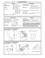
reducer) OUTPUT SPROCKET:...........Size #41 DOOR SPEED: ..........MGJ: 1Ph, 23RPM 3Ph, 39RPM LGJ: .1Ph, 43RPM BEARINGS Heavy duty wormgear-in-oil-bath speed reducer. SAFETY DISCONNECT Floor level disconnect for emergency manual door operation. REVERSING EDGE Optional) Electric or pneumatic - LiftMaster MGJ | LGJ Manual - Page 3
TO DOOR AND OPERATOR, MAKE ALL DOOR LOCKS INOPERATIVE. SECURE LOCK(S) IN "OPEN" POSITION. IF THE DOOR LOCK NEEDS TO REMAIN FUNCTIONAL, INSTALL AN INTERLOCK SWITCH. DO NOT CONNECT ELECTRIC POWER UNTIL INSTRUCTED TO DO SO. KEEP DOOR BALANCED. STICKING OR BINDING DOORS MUST BE REPAIRED. DOORS, DOOR - LiftMaster MGJ | LGJ Manual - Page 4
side up) configuration. To install an LGJ Operator on the left hand side of your door (motor side down), complete the open switch. IMPORTANT: Refer to page 9 for for complete instructions on setting of limit switches. 2. Thread the release cable through the slot on the outermost edge of the support - LiftMaster MGJ | LGJ Manual - Page 5
SUPPORT BRACKET RELEASE CABLE SLOT HOUR GLASS CABLE SLEEVE KEY RING FIGURE 2 SASH CHAIN Disconnect Cable Re-routed for Left Hand Mounting LABEL SILK SCREEN FIGURE 3 5 - LiftMaster MGJ | LGJ Manual - Page 6
to Figure 4. OPTIONAL (LGJ) Mounting Bracket OPTIONAL (MGJ) Mounting Bracket P/N 10-9098 Typical Right Hand Wall Mounted Operator FIGURE 3 IMPORTANT: The shelf or bracket must provide adequate support, prevent play between operator and door shaft, and permit operator to be fastened securely and - LiftMaster MGJ | LGJ Manual - Page 7
OFF POWER TO THE OPERATOR BEFORE MANUALLY OPERATING YOUR DOOR. Pull sash chaiWn anAd sRecNureING in bracket for manual operation of the door. This operator a floor level disconnect chain to disconnect the door from the door operator allowing for manual operation of the door in case of emergency - LiftMaster MGJ | LGJ Manual - Page 8
MANUALLY MOVING LIMIT NUTS. 3. Adjust open limit nut so that door will stop in open position with the bottom of the door even with top of door opening. 4. Repeat Steps 1 and 2 for close cycle. Adjust close limit nut so that actuator is engaged as door fully seats at the floor. If other problems - LiftMaster MGJ | LGJ Manual - Page 9
threaded shaft that transverse the shaft as the operator opens and closes the door. When a limit nut nears the end of the shaft, it activates a switch(es). B. Manually raise the door to a nearly open position. (see page 17, Manual Operation) WARNING C. Depress the limit nut retaining bracket away - LiftMaster MGJ | LGJ Manual - Page 10
Manual Disconnect Bearings & Shafts PROCEDURE Check for excessive slack. Check & adjust as required. Lubricate.* Check set screw tightness Check & tighten as required Check & Operate NUMBER DESCRIPTION MODEL NUMBER ADDRESS ORDER TO: THE CHAMBERLAIN GROUP, INC. Electronic Parts & Service Dept. 2301 - LiftMaster MGJ | LGJ Manual - Page 11
customer service department @ 1-800-528-2806. MODEL LGJ Standard G2 Wiring Model LGJ operators are supplied with type G2 control wiring. Study the control features list below to determine the features and type of control equipment that may be used with your operator. Entry Controls: OPEN control - LiftMaster MGJ | LGJ Manual - Page 12
DIAGRAM for MGJ (OPTIONAL) LIGHT W MAX. 100W (OPTIONAL) BIMETAL RELAY C B BK A W WIRE NUT CLOSE-B BL Y C N.O. W RES. Y (HOT) L2 BK OPEN-A Y CAPACITOR R MOTOR * BK O/L L1 (N) BR R BK 3 STOP 4 Y MOVE JUMPER WIRE TO TERMINAL #2 FOR MOMENTARY CONTACT ON CLOSE WIRE NUT - LiftMaster MGJ | LGJ Manual - Page 13
5 5 6 CL 1 2 (PUR) TO MOTOR (BK) (YEL) (BK) 5 (BRN) (YEL) 14 OP 1 (OR) 13 OVERLOAD (IN MOTOR) PRI. (BRN) T1 (SEE NOTE #1) 24VAC SEC. (YEL) OPEN (OR) (OR) LIMIT SWITCH (OR) WIRE OP A1 A2 NC C NUT AUX. CLOSE 10 (GY) LIMIT SWITCH NC C (GY) (RED) R1 (RED) R3 (RED) (OR - LiftMaster MGJ | LGJ Manual - Page 14
1666 SINGLE PHASE SCHEMATIC DIAGRAM for LGJ 14 - LiftMaster MGJ | LGJ Manual - Page 15
LGJ CONTROL CONNECTION DIAGRAM 41B6 LISTED DOOR OPERATOR NUMBERED BOXES CORRESPOND WITH TERMINALS ON TO TERMINAL 5. 3 5 OPEN AND CLOSE CONTROL OPTIONS WHEN CONNECTING AN OPEN CONTROL TO: 11 - Open control will require constant pressure to keep door moving. 9 - Open control will only require - LiftMaster MGJ | LGJ Manual - Page 16
LGJ Below are replacement kits available for your operator. Optional modifications and/or accessories included with your operator may add or remove certain components from these lists. Please consult a parts and service -1025C1 Model LGJ2511 Disconnect Assembly Kit K75-12583 Model LGJ2511 COMPLETE - LiftMaster MGJ | LGJ Manual - Page 17
LGJ ELECTRICAL BOX - ILLUSTRATED PARTS L3 1 L1 L10 L5 L9 7 L10 L3 L8 L7 L2 WARNING 4 3 S2 WARNING S8 S1 S6 S3 S4 S5 2 6 5 S7 L2 L6 L10 L4 8 9 17 - LiftMaster MGJ | LGJ Manual - Page 18
REPLACEMENT PART LISTS - MODEL LGJ Refer to the parts lists below for replacement kits available for your operator. If optional modifications and/or accessories are included with your operator, certain components may be added or removed from these lists. Individual components of each kit may not be - LiftMaster MGJ | LGJ Manual - Page 19
LGJ ILLUSTRATED PARTS D3 1 D11 D12 D5 D1 D9 3 D7 D2 D8 D6 D13 D4 D9 19 5 2 7 8 4 6 D10 - LiftMaster MGJ | LGJ Manual - Page 20
be sure to match model number of your unit to kit number below to ensure proper voltage requirements. Optional modifications and/or accessories included with your operator may add or remove certain components from these lists. Please consult a parts and service representative regarding availability - LiftMaster MGJ | LGJ Manual - Page 21
MGJ ELECTRICAL BOX - ILLUSTRATED PARTS 1 L8 L6 L2 9 S3 S9 S7 S4 S6 S3 S5 6 S2 S8 6 8 S3 S7 5 S1 S6 S4 S3 10 L3 L1 L7 3 L3 7 4 L2 L5 L4 2 21 - LiftMaster MGJ | LGJ Manual - Page 22
operator, certain components may be added or removed from these lists. Individual components of each kit may not be available. Please consult a parts and service Gear Yoke 1 2 10-11359 Front Bracket 1 D3 10-11358 Disconnect Support Bracket 1 3 32-11414 Gear Reducer, 45:1 1 D4 10-11394 - LiftMaster MGJ | LGJ Manual - Page 23
D8 D13 D4 D13 D2 D12 D5 D14 D11 2 4 ILLUSTRATED PARTS - MODEL MGJ 23 D3 3 1 D10 D9 D7 5 D1 D15 D6 D15 - LiftMaster MGJ | LGJ Manual - Page 24
Refer to page 15 for model LGJ control connections) 1) The 3-Button Control Station provided must be connected for operation. ATTENTION ELECTRICIAN: 2) TYPES * T1 WIRING - RADIO TO OPEN ONLY EXTERNAL INTERLOCK Warning Light will activate 15 sec. before door closes. 11 12 13 14 Auxiliary Terminal
-
 1
1 -
 2
2 -
 3
3 -
 4
4 -
 5
5 -
 6
6 -
 7
7 -
8
-
9
-
10
-
11
-
12
-
13
-
14
-
15
-
16
-
17
-
18
-
19
-
20
-
21
-
22
-
23
-
24
 |
 |

OWNER'S MANUAL
MODELS:
LGJ & MGJ
INDUSTRIAL DUTY DOOR OPERATOR
NOT FOR RESIDENTIAL USE
LISTED
DOOR
OPERATOR
41B6
Serial #
(located on electrical box cover)
Installation Date
Wiring Type
2
YEAR
WARRANTY