LiftMaster SW490 SW490 GL BOARD Manual
LiftMaster SW490 Manual
 |
View all LiftMaster SW490 manuals
Add to My Manuals
Save this manual to your list of manuals |
LiftMaster SW490 manual content summary:
- LiftMaster SW490 | SW490 GL BOARD Manual - Page 1
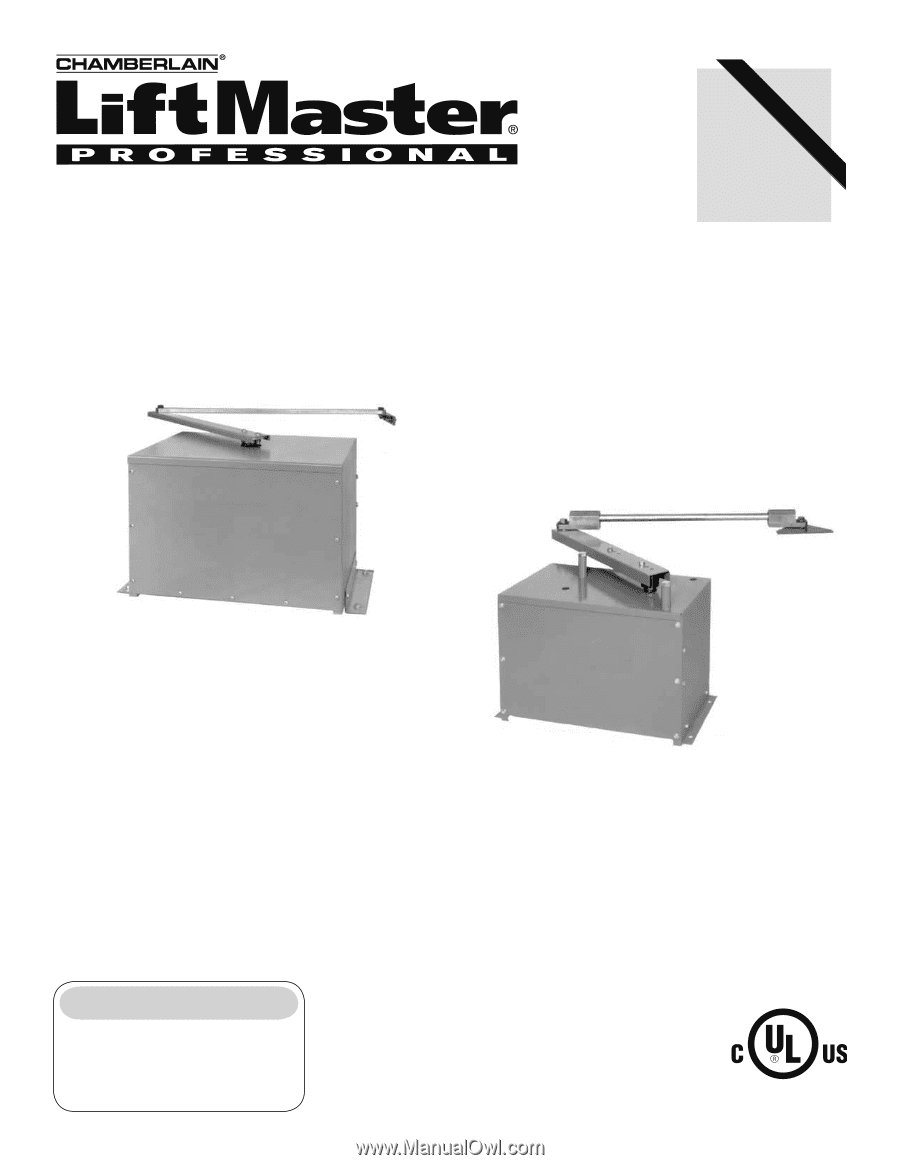
DUTY SWING GATE OPERATOR 2 YEAR WARRANTY Serial located on electrical box cover) Installation Date INTENDED FOR PROFESSIONAL INSTALLATION ONLY. VISIT WWW.LIFTMASTER.COM TO LOCATE A PROFESSIONAL INSTALLING DEALER IN YOUR AREA. THIS MANUAL IS TO BE LEFT WITH THE PROPERTY OWNER. MODELS SW470 AND - LiftMaster SW490 | SW490 GL BOARD Manual - Page 2
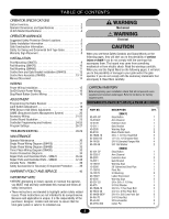
-38 Variable Parts - SW490 39 Safety Accessories for Secondary Entrapment Protection . . . . .39 WPARRRAENCTYAPOULICCYIÓANND SERVICE 40 IMPORTANT NOTE • BEFORE attempting to install, operate or maintain the operator, you MUST read and fully understand this manual and follow all safety instructions - LiftMaster SW490 | SW490 GL BOARD Manual - Page 3
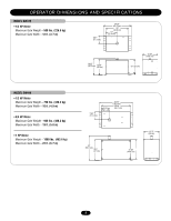
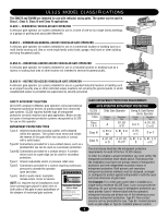
OPERATOR DIMENSIONS AND SPECIFICATIONS MODEL SW470 • 1/2 HP Motor Maximum Gate Weight - 500 lbs. (226.8 kg) Maximum Gate Width - 12 ft. (3.7 m) 6.81" (17.3 cm) 24.25" (61.6 cm) 20" (50.8 cm) 10" (25.4 cm) 14.25" (36.2 cm) 13.38" (34 cm) 13.63" (34.6 cm) 13" (33 cm) MODEL SW490 • 1/2 HP Motor - LiftMaster SW490 | SW490 GL BOARD Manual - Page 4
locations not servicing the general public, in which unauthorized access is prevented via supervision by security personnel. SAFETY ACCESSORY SELECTION All UL325 compliant LiftMaster gate operators will accept external entrapment protection devices to protect people from motorized gate systems - LiftMaster SW490 | SW490 GL BOARD Manual - Page 5
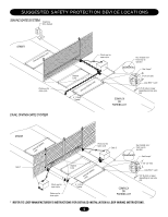
to operator Seal Loops* Gate 1 Photo eye for open cycle Photo eye for close cycle Shadow Loop InLteororuppt (Safety) 4' (1.2 m) Typical COMPLEX OR PARKING LOT 1-1/2" (37 mm) Loop Wire* Layer 1/4" (6 mm) or larger depending on loop wire size * REFER TO LOOP MANUFACTURER'S INSTRUCTIONS FOR - LiftMaster SW490 | SW490 GL BOARD Manual - Page 6
Rollers • Vertical Posts • Photoelectric Sensors • Instructional and Precautionary Signage 4. Install the gate operator only when: a. The operator is appropriate for the construction and the usage class of the gate. b. All openings of a horizontal slide gate are guarded or screened from the bottom - LiftMaster SW490 | SW490 GL BOARD Manual - Page 7
the operator requires replacement, shall be upgraded to conform to the provisions of this specification in effect at that time. 3. VEHICULAR HORIZONTAL SLIDE GATES 3.1 The following provisions shall apply to Class I, Class II and Class III vehicular horizontal slide gates: 3.1.1 All weight bearing - LiftMaster SW490 | SW490 GL BOARD Manual - Page 8
. • Locate entrapment protection devices to protect in BOTH the open and close gate cycles. • Locate entrapment protection devices to protect between moving gate and RIGID objects, such as posts. • A swinging gate shall NOT open into public access ways. AVERTISSEMENT WARNING SIGN PALATCTEMEENNT TION - LiftMaster SW490 | SW490 GL BOARD Manual - Page 9
INSTALLATION POST MOUNTING (SW470) 1. Locate and anchor two posts made of 3" (7.6 cm) outer diameter heavy walled pipe. Posts should be parallel and square to the gate. IMPORTANT NOTE: The distance between mounting posts and the relative location of the operator to the gate and fence is critical. - LiftMaster SW490 | SW490 GL BOARD Manual - Page 10
22-1/2" 24" 8" 1/2" Redhead (4 required.) Concrete pad 18"x34" min. Operator Parallel Mount Centerline Gate 6" 8" 18-3/4" 8"16"1/2" Redhead (4 required) Figure 2 Concrete pad 18"x34" min. 22-1/2" Profile of Operator SW470 Perpendicular Perpendicular Mount 1/2" red head bolts or anchors - LiftMaster SW490 | SW490 GL BOARD Manual - Page 11
the pad. It is very important that the operator be level and square to the gate. Figure 1 P Gate 5" Output Shaft Fence 1/2" Redhead (4 Required) 8" Operator 28" Concrete Pad 18" x 34" min. Figure 2 SW490 GATE OPERATOR INSTALLATION TABLE GATE LENGTH (FEET) 8-9 10-11 12-13 14-15 16-17 18-19 - LiftMaster SW490 | SW490 GL BOARD Manual - Page 12
CAUTION If the arm stop is installed incorrectly, the gate will be prevented from opening and damage to the operator may result! Figure 1 Close Stops Left hand Right hand AVERTISSEMENT installation installation SW470 Parallel to Fence ATTCEloseNStopTs ION Arm Channel Housing Hub Assembly - LiftMaster SW490 | SW490 GL BOARD Manual - Page 13
this application. Use any existing hardware necessary to seal the open stop's hole in the operator's cover. 3. Measure the length of the gate panel and select the appropriate extension arm (x) and control arm (Y) dimensions from the gate installation table. 4. Install the control arm hub assembly to - LiftMaster SW490 | SW490 GL BOARD Manual - Page 14
to pivot dimension. Weld or bolt extension arm to arm assembly. MANUAL DISCONNECT MODEL SW470 1. Remove the (2) black knobs securing the control arm to the operator (Figure 1). 2. Swing arm assembly off to the side. Gate should swing freely. Figure 1 Arm Channel MODEL SW490 1. Remove hitch pin - LiftMaster SW490 | SW490 GL BOARD Manual - Page 15
operator • ANY maintenance to the operator or in the area near the operator returned to service. visible and Gate System, each unit must be installed on ITS OWN separate circuit. WIRE GAUGE 6 • 1/2 HP Motor ------• 3/4 HP Motor ------• 1 HP Motor conditions must be reviewed for suitability of - LiftMaster SW490 | SW490 GL BOARD Manual - Page 16
ON/OFF Switch Cover Wire Nut Connections (See Instructions) Power Wiring Conduit STOP/RESET BUTTON CONTROL WIRING (REQUIRED) 1. This control will function as a Stop/Reset command and is to be wired within line of sight of the gate. The operator will not function unless this circuit is completed - LiftMaster SW490 | SW490 GL BOARD Manual - Page 17
that you wish to operate your garage door. The opener will now operate when the push to operate, or play with remote control transmitters. • Activate gate or replacing the battery. THERE ARE NO OTHER USER SERVICEABLE PARTS. WARNING Tested to Comply with FCC Standards FOR HOME OR OFFICE USE. Operation - LiftMaster SW490 | SW490 GL BOARD Manual - Page 18
arm from gate bracket so gate is no longer connected to operator. Push manual release pin(s) OPEN LIMIT SWITCH 8. Turn on power. Press OPEN button (if installed) or connect terminals 5 & 7 on J1 terminal strip. Gate should open. If gate does not open the open limit cam may be already actuating open - LiftMaster SW490 | SW490 GL BOARD Manual - Page 19
BEFORE performing ANY adjustments. These operators use an internal entrapment protector system measure the distance. 3. Tighten screws to secure assembly. 4. Manually rotate pulley to ensure that each magnet clears the sensor board ) assembly accordingly. MODEL SW470 Hall Effect Cable Mounting - LiftMaster SW490 | SW490 GL BOARD Manual - Page 20
the demands of speed during high traffic periods with security during low traffic periods. Barrier gates typically have the fastest open times of the many gate operator types and the slide or swing gates allow you to effectively seal off the perimeter of the complex you are planning to secure - LiftMaster SW490 | SW490 GL BOARD Manual - Page 21
manual. Refer to instructions shipped with optional control devices for mounting, wiring, programming and adjustment. 1 2 3 4 5 6 7 8 9 10 11 and is primarily used on swing gate operators. This input protects cars by preventing the gate from moving off of the open or close limit when the shadow - LiftMaster SW490 | SW490 GL BOARD Manual - Page 22
gate. This input functions to stop the gate or to reset the gate after an entrapment fault. NOTE: This input uses a normally closed circuit and the operator of the gate. A momentary activation of this input will cause the gate to 1 2 3 4 5 6 7 8 9 10 11 12 13 14 15 16 OPEN OPEN open. Activation - LiftMaster SW490 | SW490 GL BOARD Manual - Page 23
Timer-to-Close Potentiometer Force Adjustment Dip Switch #2 Dip Switch #1 Diagnostic LED J2 Connector J5 Connector SAMS Relay Drive Troubleshooting LEDs J1 Terminal Troubleshooting LEDs Limit LEDs Programming Port (factory use only) Motor Learn Button J3 Connector Aux. Relay Drive (not used) 23 - LiftMaster SW490 | SW490 GL BOARD Manual - Page 24
in stand alone mode. 1. The operator must remain attached to the gate throughout the entire process. 2. Press the motor learn button. The yellow LED should start to flash rapidly. 3. Install a jumper on either the hard open or the hard close input terminals. The motor will run for a few seconds and - LiftMaster SW490 | SW490 GL BOARD Manual - Page 25
is activated On when Alarm Relay is activated TROUBLESHOOTING LEDS There are 9 troubleshooting LEDs. LED D11 D13 D15 D17 (Green) D19 D21 D24 D29 LED NAME Radio Shadow Hard Close Stop Soft Open Hard Open Interrupt (Safety) Loop Obstruction Open D31 Obstruction Close DESCRIPTION On when Radio - LiftMaster SW490 | SW490 GL BOARD Manual - Page 26
2 34 LT SL LT SL (Factory Default) SLIDE/SWING This switch selects slide or swing gate operation, in order to optimize gate behavior for specific application. SL = Slide • SW = Swing RIGHT/LEFT OPERATION This switch selects the gate opening direction, to the left or to the right. Right/Left - LiftMaster SW490 | SW490 GL BOARD Manual - Page 27
or hard open input. EDGE CLOSE PHOTO CLOSE CLED OPED WARN MAG CLED OPED WARN MAG S2 ON ON 1 2 34 S2 ON ON 1 2 34 PH PH PH PH MASTER/SECOND SYSTEMS Dual Gate Communications The control board is capable of running the operator in a master or second mode depending on (S4) switch setting - LiftMaster SW490 | SW490 GL BOARD Manual - Page 28
2. If operator is in a dual gate configuration dip switches operator by consulting the wiring specifications section on page 15 of this manual. Problem in the motor. Perform a visual inspection of the motor. Examine the motor's labels for any distortion or signs of over heating. Replace the motor - LiftMaster SW490 | SW490 GL BOARD Manual - Page 29
gate. Both LEDs will indicate the activation of entrapment protection devices on terminals J1-9 & J1-10 on the control board. Remove the devices and retest. If the operator now runs without fault, check those accessories as well as their wiring. The operator opens the pulley. Replace the sensor if - LiftMaster SW490 | SW490 GL BOARD Manual - Page 30
To reduce the risk of SEVERE INJURY or DEATH: 1. READ AND FOLLOW ALL INSTRUCTIONS. 6. Keep gates properly maintained. Read the owner's 2. NEVER let children operate or play with gate controls. Keep manual. Have a qualified service person make repairs to the remote control away from children - LiftMaster SW490 | SW490 GL BOARD Manual - Page 31
SINGLE PHASE WIRING DIAGRAM (SW470) 1 PHASE POWER IN SWITCH NOTE 1 MOTOR GROUND GL CONTROL BOARD J2 PLUG 24 Vac - IN 24 Vac - COMMON SOFT OPEN NC "B" LIMIT CONTACTOR B NOTE 1 PRIMARY 24V SEC. SEE NOTE 2 R 2 SEE NOTE 4 ALARM ASSY 76-G0564 "A" LIMIT CONTACTOR A RPM - IN RPM - SUPPLY RPM GND - LiftMaster SW490 | SW490 GL BOARD Manual - Page 32
. OPEN OBS. CLOSE 24 Vac - COMMON DC - GND LOCK 1 LOCK 2 ALARM 1 ALARM 1 1 2 J4 DUAL GATE RPM SENSOR R4 B+ ALARM ASSY 76-G0564 LEGEND PERMANENT TERMINAL J1 TERMINAL BLOCK TERMINAL BLOCK R 1 R 2 R 3 R 4 24 Vac RADIO SIGNAL NOTES: 1) TRANSFORMER PRIMARY VOLTAGE SAME AS OPERATOR LINE - LiftMaster SW490 | SW490 GL BOARD Manual - Page 33
MOTOR "A" LIMIT CONTACTOR A RPM - IN RPM - SUPPLY RPM GND RADIO COMMAND SHADOW +24 Vdc CLOSE STOP SOFT OPEN HARD OPEN INT. LOOP OBS. OPEN OBS. CLOSE 24 Vac - COMMON DC - GND LOCK 1 LOCK 2 ALARM 1 ALARM 1 RPM SENSOR J2 PLUG (OPTIONAL) R 3 R 4 SEE NOTE 5 B+ ALARM ASSY 76-G0564 1 2 J4 DUAL GATE - LiftMaster SW490 | SW490 GL BOARD Manual - Page 34
the controls. Also, always install the controls where the user has full view of gate operation. * All inputs are normally open and momentary, except the stop (N.C.). The following instructions are based upon UL325, and include recommendations for significant increase in safety. * We strongly - LiftMaster SW490 | SW490 GL BOARD Manual - Page 35
-11 (Operator) = K73SW420-33-11 (Electrical Box Kit) Motor Kits To order a motor replacement kit, add a K prefix to the number of your motor and remove the second dash (-). For example: 20-5752-33 (Motor Number) = K20-575233 (Motor Kit) ITEM 1 2 3 4 5 6 7 8 9 10 11 12 13 14 INDIVIDUAL PARTS PART - LiftMaster SW490 | SW490 GL BOARD Manual - Page 36
ILLUSTRATED PARTS - SW470 A2 A3 D8 D9 D3 1 A7 A1 A4 A6 A5 9 D1 D12 6 4 D2 D4 D11 10 3 5 7 D10 13 D6 1 8 2 D5 D7 11 14 12 36 - LiftMaster SW490 | SW490 GL BOARD Manual - Page 37
SW420-33-11 (Operator) = K73SW420-33-11 (Electrical Box Kit) Motor Kits To order a motor replacement kit, add a K prefix to the number of your motor and remove the second dash (-). For example: 20-5752-33 (Motor Number) = K20-575233 (Motor Kit) ITEM 1 2 3 4 5 6 7 8 INDIVIDUAL PARTS PART# 10-18458 - LiftMaster SW490 | SW490 GL BOARD Manual - Page 38
ILLUSTRATED PARTS - SW490 A5 A1 A4 A3 A5 A2 D10 A7 D11 D5 D21 D20 D1 D12 D18 D12 D17 D4 D3 6 3 D14 D15 D6 D19 D13 8 1 A6 5 2 4 D7 D16 D2 E5 E3 D8 D9 F E1 7 E4 E2 38 - LiftMaster SW490 | SW490 GL BOARD Manual - Page 39
PARTS - SW490 PART 20-XXXX (Motor) 23-XXXX (Switch) 24-XXX-X (Relay) 25-20XX (Overload) 25-40XX (Overload) PART -50-21, SW490-75-21 SW490-33-11 SW490-50-11, SW490-100-21 SW490-75-11 SW490-100-11 SW490 long). Miller MG020 2-wire electric edge for gates. Sensitized on three sides. Requires mounting - LiftMaster SW490 | SW490 GL BOARD Manual - Page 40
AMERICA FOR INSTALLATION AND SERVICE INFORMATION, CALL OUR TOLL FREE NUMBER 1-800-528-2806 www.liftmaster.com WHEN ORDERING REPAIR PARTS PLEASE SUPPLY THE FOLLOWING INFORMATION: PART NUMBER DESCRIPTION MODEL NUMBER ADDRESS ORDER TO: THE CHAMBERLAIN GROUP, INC. Technical Support Group 6020 Country
-
 1
1 -
 2
2 -
 3
3 -
 4
4 -
 5
5 -
 6
6 -
 7
7 -
8
-
9
-
10
-
11
-
12
-
13
-
14
-
15
-
16
-
17
-
18
-
19
-
20
-
21
-
22
-
23
-
24
-
25
-
26
-
27
-
28
-
29
-
30
-
31
-
32
-
33
-
34
-
35
-
36
-
37
-
38
-
39
-
40
 |
 |
CONTROLLER BOARD
GL
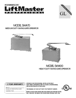
MODELS SW470 AND SW490 ARE FOR VEHICULAR PASSAGE GATES
ONLY AND NOT INTENDED FOR PEDESTRIAN PASSAGE GATE USE.
MODEL SW470
MEDIUM DUTY SWING GATE OPERATOR
Serial # _______________________
(located on electrical box cover)
Installation Date_________________
2 YEAR WARRANTY
MODEL SW490
HEAVY DUTY SWING GATE OPERATOR
INTENDED FOR PROFESSIONAL INSTALLATION ONLY.
VISIT WWW.LIFTMASTER.COM TO LOCATE A PROFESSIONAL
INSTALLING DEALER IN YOUR AREA.
THIS MANUAL IS TO BE LEFT WITH THE PROPERTY OWNER.