MSI 790GX-G65 User Guide
MSI 790GX-G65 - SocketAM3/140W CPU/AMD 790GX Manual
 |
UPC - 816909055658
View all MSI 790GX-G65 manuals
Add to My Manuals
Save this manual to your list of manuals |
MSI 790GX-G65 manual content summary:
- MSI 790GX-G65 | User Guide - Page 1
790GX-G65 series MS-7576 (v1.X) Mainboard G52-75761X1 - MSI 790GX-G65 | User Guide - Page 2
's manual, please contact your place of purchase or local distributor. Alternatively, please try the following help resources for further guidance. Visit the MSI website for FAQ, technical guide, BIOS updates, driver updates, and other information: http://global.msi.com.tw/index.php? func=service - MSI 790GX-G65 | User Guide - Page 3
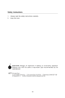
1. Always read the safety instructions carefully. 2. Keep this User's Manual for future reference. 3. Keep this . 11. If any of the following situations arises, get the equipment checked by a service personnel: † The power cord or plug is damaged. † Liquid has penetrated into the equipment - MSI 790GX-G65 | User Guide - Page 4
installation. This equipment generates, uses and can radiate radio frequency energy and, if not installed and used in accordance with the instructions VOIR LANOTICE D'INSTALLATIONAVANT DE RACCORDER AU RESEAU. Micro-Star International MS-7576 This device complies with Part 15 of the FCC Rules. - MSI 790GX-G65 | User Guide - Page 5
WEEE (Waste Electrical and Electronic Equipment) Statement v - MSI 790GX-G65 | User Guide - Page 6
vi - MSI 790GX-G65 | User Guide - Page 7
vii - MSI 790GX-G65 | User Guide - Page 8
History ...ii Technical Support ...ii Safety Instructions ...iii FCC-B Setup 2-1 Quick Components Guide 2-2 CPU (Central Processing Unit 2-3 Memory ...2-6 Power Supply ...2-8 Back Panel ...2-9 Connectors ...2-11 Buttons ...2-18 Switc h ...2-19 Slots ...2-20 Chapter 3 BIOS Setup 3-1 Entering Setup - MSI 790GX-G65 | User Guide - Page 9
Appendix B Overclocking Center B-1 Activating Overclocking Center B-2 System Info ...B-3 DOT ...B-5 Appendix C SATA RAID C-1 RAID Configuration C-2 ix - MSI 790GX-G65 | User Guide - Page 10
Thank you for choosing the 790GX-G65 Series (MS7576 v1.X) ATX mainboard. The 790GX-G65 Series mainboards are based on AMD 790GX/780G & SB710/ SB750 chipset for optimal system efficiency. Designed to fit the advanced 64bit AMD Phenom II processor, the 790GX-G65 Series deliver a high performance and - MSI 790GX-G65 | User Guide - Page 11
AM3 package. (For the latest information about CPU, please visit ht t p : / / global. m s i. c om . t w / ind ex. php ?func = c pufor m 2) HyperTransport - Hyper Transport 3.0 up to 5.2GT/s Chipset - North Bridge: AMD® 790GX / 780G chipset - South Bridge: AMD® SB710 / SB750 chipset Memory Support - MSI 790GX-G65 | User Guide - Page 12
- 1 Power LED Button - 1 Reset LED Button - 1 Clear CMOS Button Slots For 790GX - 1 PCI Express x16 slot supports up to PCI Express x16 speed. When dual graphic cards enabled, it will turn to x8 speed. - 1 PCI Express x16 slot supports up to PCI Express x8 speed - 2 PCI Express x1 slots - 2 PCI slot - MSI 790GX-G65 | User Guide - Page 13
IDE1 SYSFAN1 SYSFAN2 S Y S FA N 3 S ATA 2_3 S ATA4_ 5 JTPM1 JFP1 JFP2 JAUD1 JCD1 JSP1 J1394_1 (opt i on al) BATT + JSPI1 SATA1 FDD1 JUSB1 JUSB2 JUSB3 JCOM1 790GX-G65 Series (MS-7576 v1.X) ATX Mainboard 1-4 - MSI 790GX-G65 | User Guide - Page 14
Packing Checklist Getting Started MSI motherboard MSI Driver/Utility DVD SATA Cable Power Cable Standard Cable for IDE Devices Back IO Shield User's Guide * The pictures are for reference only and may vary from the packing contents of the product you purchased. 1-5 - MSI 790GX-G65 | User Guide - Page 15
chapter provides you with the information about hardware setup procedures. While doing the installation, be careful in holding the components and follow the installation procedures. For some components, if you install in the wrong orientation, the components will not work properly. Use a grounded - MSI 790GX-G65 | User Guide - Page 16
MS-7576 Mainboard Quick Components Guide PWR1, p.2-8 CPU, p.2-3 DDR3, p.2-6 CPUFAN1, p.2-13 Back Panel I/O, p.2-9 SYSFAN1/2, p.2-13 PCIE, p.2-20 PCI, p.2-25 FDD1, p.2-11 J1394_1, p.2-12 JSP1, p.2-17 JCD1, p.2-16 JAUD1, p.2-17 JPWR1, p.2-8 IDE1, p.2-11 OCSWITCH1, p.2-19 - MSI 790GX-G65 | User Guide - Page 17
Hardware Setup CPU (Central Processing Unit) W hen you are installing the CPU, make sure to install the cooler to prevent overheating. If you do not have the CPU cooler, consult your dealer before turning on the computer. For the latest information about CPU, please visit http://global.msi.com.tw/ - MSI 790GX-G65 | User Guide - Page 18
MS-7576 Mainboard CPU & Cooler Installation W hen you are installing the CPU, make sure the CPU has a cooler attached on the top to prevent overheating. Meanwhile, do not forget to apply some thermal paste on CPU before installing the heat sink/cooler fan for better heat dispersion. Follow the - MSI 790GX-G65 | User Guide - Page 19
Hardware Setup 5. Position the cooling set onto the retention mechanism. Hook one the lever. 8. Attach the CPU Fan cable to the CPU fan connector on the mainboard. Important 1. Mainboard photos shown in this section are for demonstration of the cooler installation for Socket AM2+ CPUs only. The - MSI 790GX-G65 | User Guide - Page 20
MS-7576 Mainboard Memory These DIMM slots are used for installing memory modules. For more information on compatible components, please visit http://global.msi.com. tw/index.php?func=testreport DDR3 240-pin, 1.5V 48x2=96 pin 72x2=144 pin Dual-Channel: Channel A in SKYBLUE; Channel B in PINK - MSI 790GX-G65 | User Guide - Page 21
the DIMM slot. 3. Manually check if the memory module has been locked in place by the DIMM slot clips at the sides. Volt Notch Important - DDR3 memory modules are not interchangeable with DDR2 and the DDR3 standard is not backwards compatible. You should always install DDR3 memory modules in the - MSI 790GX-G65 | User Guide - Page 22
MS-7576 Mainboard Power Supply ATX 24-Pin Power Connector: JPWR1 This connector allows you to connect an ATX 24-pin power supply. To connect the ATX 24-pin power supply, make sure the plug of the power supply is inserted in the proper orientation and the pins are aligned. Then push - MSI 790GX-G65 | User Guide - Page 23
Hardware Setup Back Panel Optical S/PDIF-Out VGA manual for more information.) HDMI Port The High-Definition Multimedia Interface (HDMI) is an all-digital audio/video interface capable of transmitting uncompressed streams. HDMI supports supports RAID and AHCI mode (does not support IDE mode) 2-9 - MSI 790GX-G65 | User Guide - Page 24
MS-7576 Mainboard USB Port The USB (Universal Serial Bus) port is for attaching USB devices such as keyboard, mouse, or other USB-compatible devices. LAN The - MSI 790GX-G65 | User Guide - Page 25
Hardware Setup Connectors Floppy Disk Drive Connector: FDD1 This connector supports 360KB, 720KB, 1.2MB, 1.44MB or 2.88MB floppy disk drive. FDD1 IDE Connector: IDE1 This connector supports IDE hard disk drives, optical disk drives and other IDE devices. IDE1 Important If you install two IDE devices - MSI 790GX-G65 | User Guide - Page 26
MS-7576 Mainboard Serial ATA Connector: SATA1~5 This connector is a high-speed Serial ATA interface port. Each connector can connect to one Serial ATA device. SATA1 SATA4_5 SATA2_3 Important 1. SATA5 only supports RAID and AHCI mode (does not support IDE mode) 2. Please do not fold the Serial - MSI 790GX-G65 | User Guide - Page 27
a System Hardware Monitor chipset on-board, you must use a specially designed fan with speed sensor to take advantage of the CPU fan control. GND CPU fans at processor's official website or consult the vendors for proper CPU cooling fan. 2. CPUFAN1 supports fan control. You can install Overclocking - MSI 790GX-G65 | User Guide - Page 28
MS-7576 Mainboard Front USB Connector: JUSB1~3 This connector, compliant with Intel® I/O Connectivity Design Guide, is ideal for connecting high-speed USB interface peripherals such as USB HDD, digital cameras, MP3 players, printers, modems and the like. 9 1 10 2 JUSB1~3 Pin - MSI 790GX-G65 | User Guide - Page 29
Hardware Setup TPM Module connector: JTPM1(optional) This connector connects to a TPM (Trusted Platform Module) module (optional). Please refer to the TPM security platform manual for more details and usages. 14 13 21 Pin Signal Description 1 LCLK LPC clock 3 LRST# LPC reset 5 LAD0 LPC - MSI 790GX-G65 | User Guide - Page 30
MS-7576 Mainboard Front Panel Connectors: JFP1, JFP2 These connectors are for electrical connection to the front panel switches and LEDs. The JFP1 is compliant with Intel® Front Panel I/O Connectivity Design Guide. JFP1 10 Power Switch + Power LED 2 9 + Reset - Switch - HDD 1 +LED JFP2 +8 7 - MSI 790GX-G65 | User Guide - Page 31
Hardware Setup S/PDIF-Out Connector: JSP1 This connector is used to connect S/PDIF ( connector allows you to connect the front panel audio and is compliant with Intel® Front Panel I/O Connectivity Design Guide. 2 1 10 9 JAUD1 PIN SIGNAL 1 MIC_L 2 GND 3 MIC_R 4 PRESENCE# 5 LINE out_R - MSI 790GX-G65 | User Guide - Page 32
MS-7576 Mainboard Buttons The motherboard provides the following button for you to set the computer's function. This section will explain how to change your motherboard's function through the use of button. Clear CMOS Button: CLR_CMOS1 There is a CMOS RAM on board that has a power supply from - MSI 790GX-G65 | User Guide - Page 33
FSB Switch: OCSWITCH1 You can overclock the FSB to increase the processor frequency by changing the switch. Follow the instructions below to set the FSB. DOC1 1:ON 1:ON 1:OFF 1:OFF DOC2 2:ON 2:OFF 2:ON 2:OFF CPU Frequency Default Increase 10% speed of FSB Increase 15% speed of FSB Increase - MSI 790GX-G65 | User Guide - Page 34
MB/s transfer rate. PCIE slot allocation for 790GX chipset PCI_E1 supports up to PCI Express x16 speed. When dual graphic cards enabled, it will turn to x8 speed. PCI_E2 supports up to PCI Express x1 speed. PCI_E3 supports up to PCI Express x1 speed. PCI_E4 supports up to PCI Express x8 speed. PCIE - MSI 790GX-G65 | User Guide - Page 35
are installed on PCI_E1 & PCI_E4 slots. 3. Make sure that you connect an adequate power supply to the power connector on the graphics card to ensure stable operation of the graphics card. 4. Only Windows® XP with Service Pack 2 (SP2)& Windows® XP Profes -sional x64 Edition & Windows® Vista support - MSI 790GX-G65 | User Guide - Page 36
MS-7576 Mainboard 3.W hen all of the hardware and software has been properly set up and installed, reboot the system. After entering the O.S., click the "Catalyst™ Alternate Frame Rendering • Super Anti-aliasing. for more details, please consult the graphics card manual from the manufacturer. 2-22 - MSI 790GX-G65 | User Guide - Page 37
3. Mainboard based on an AMD 780 integrated chipset. Enabling Hybrid CrossFireXTM Technology Power off the system and install the ATI graphic card that supports Hybrid CrossFireX technology. After then, power on the system and install the driver that Hybrid CrossFireX technology. Restart the system - MSI 790GX-G65 | User Guide - Page 38
graphic memory operating mode may cause Hybrid CrossFire fail. To avoid the issue, please follow the steps below to setup the system: 1. Disable the Hybrid CrossFire in Catalyst Control Center. 2. Reboot into BIOS 3. Select the option in Advanced BIOS Features -> Chipset Feature -> On-Chip VGA - MSI 790GX-G65 | User Guide - Page 39
Hardware Setup PCI (Peripheral Component Interconnect) Slot The PCI slot supports LAN cards, SCSI cards, USB cards, and other add- or software settings for the expansion card, such as jumpers, switches or BIOS configuration. PCI Interrupt Request Routing The IRQ, acronym of interrupt request line - MSI 790GX-G65 | User Guide - Page 40
Chapter 3 BIOS Setup BIOS Setup This chapter provides information on the BIOS Setup program and allows you to configure the system for optimum use. You may need to run the Setup program when: ² An error message appears on the screen during the system booting up, and requests you to run SETUP. ² - MSI 790GX-G65 | User Guide - Page 41
MS-7576 Mainboard Entering Setup Power on the computer and the system will start POST (Power On Self Test) process. W hen the message below appears on the screen, press key to enter Setup. Press DEL to enter SETUP If the message disappears before you respond and you still wish to enter Setup, - MSI 790GX-G65 | User Guide - Page 42
BIOS Setup Control Keys Enter> Move to the -menu. If you want to return to the main menu, just press the . General Help The BIOS setup program provides a General Help screen. You can call up this screen from any menu by simply pressing . The - MSI 790GX-G65 | User Guide - Page 43
MS-7576 Mainboard The Main Menu Standard CMOS Features Use this menu for basic system configurations, such as time, date etc. Advanced BIOS Features Use this menu to setup the items of AMI® special enhanced features. Integrated Peripherals Use this menu to specify your settings for integrated - MSI 790GX-G65 | User Guide - Page 44
values set by the BIOS vendor for stable system performance. Load Optimized Defaults Use this menu to load the default values set by the mainboard manufacturer specifically for optimal performance of the mainboard. Save & Exit Setup Save changes to CMOS and exit setup. Exit Without Saving Abandon - MSI 790GX-G65 | User Guide - Page 45
MS-7576 Mainboard Standard CMOS Features The items in Standard CMOS Features Menu includes some basic setup items. Use the arrow keys > . day Day of the week, from Sun to Sat, determined by BIOS. Read-only. month The month from Jan. through Dec. date The date from 1 to 31 - MSI 790GX-G65 | User Guide - Page 46
BIOS Setup Device/ Vender/ Size It will showing the device information that you connected to the IDE/SATA connector. LBA/Large M ode This allows you to enable or disable the LBA Mode. Setting to Auto enables LBA mode if the device supports allows you to set the type of floppy drives installed. 3-7 - MSI 790GX-G65 | User Guide - Page 47
MS-7576 Mainboard System Information Press to enter the sub-menu, and the following screen appears. CPU Infromation/ BIOS Version/ M emory Information These items show the CPU information, BIOS version and memory status of your system (read only). 3-8 - MSI 790GX-G65 | User Guide - Page 48
Advanced BIOS Features BIOS Setup BIOS Flash Protection This function protects the BIOS from accidental corruption by unauthorized users or computer viruses. W hen enabled, the BIOS' data cannot be changed when attempting to update the BIOS with a Flash utility. To successfully update the BIOS, - MSI 790GX-G65 | User Guide - Page 49
screen appears: HPET The HPET (High Precision Event Timers) is a component that is part of the chipset. You can to enable it, and will provide you with the means to get to it via the various ACPI methods. On-chip VGA This item specifies whether to allocate the memory for onboard VGA from the 3-10 - MSI 790GX-G65 | User Guide - Page 50
BIOS Setup system memory or sideport memory. Setting to [UMA], allocates the system share memory for onboard VGA. Setting to [SIDEPORT], allocates the sideport memory for onboard VGA. Setting to [UMA+SIDEPORT], allocates both system memory and sideport memory for onbaord VGA. VGA Share Memory SUPPORT - MSI 790GX-G65 | User Guide - Page 51
MS-7576 Mainboard Integrated Peripherals USB Controller This setting allows you to enable/disable the onboard USB 1.1/ 2.0 controller. USB Device Legacy Support Select [Enabled] if you need to use a USB-interfaced device in the operating system. Onboard LAN Controller This setting allows you to - MSI 790GX-G65 | User Guide - Page 52
BIOS Setup PCI IDE BusMaster This item allows you to enable/ disable BIOS to used PCI busmastering for reading/ writing to IDE drives. OnChip SATA Controller This item allows users to enable or disable the SATA controller. RAID Mode This item is used to select mode for SATA connectors. I/O Devices - MSI 790GX-G65 | User Guide - Page 53
MS-7576 Mainboard Power Management Setup Important S3-related functions described in this section are available only when your BIOS supports lost (CPU or chipset) and memory that remains powered while most other hardware components turn off to save energy. The information stored in memory - MSI 790GX-G65 | User Guide - Page 54
State] Restores the system to the status before power failure or interrupt occurred. Wakeup Event Setup Press to enter the sub-menu, and the following screen appears. Wake Up Event By Setting to [BIOS] activates the following fields, and use the following fields to set the wake up events - MSI 790GX-G65 | User Guide - Page 55
MS-7576 Mainboard Resume by PCI-E Device W hen set to [Enabled], the feature allows your system to be awakened from the power saving modes through any event on PCIE device. Resume by RTC Alarm The field is used to enable or disable the feature of booting up the system on a scheduled time/date. 3-16 - MSI 790GX-G65 | User Guide - Page 56
H/W Monitor BIOS Setup Chassis Intrusion The field enables or disables the feature of recording the it with in a specific range. You can select a fan target value here. If the current CPU fan temperature reaches to the target value, the smart fan function will be activated. It provides several - MSI 790GX-G65 | User Guide - Page 57
MS-7576 Mainboard Green Power CPU Phase Control W hen set to [Auto], the hardware will auto adjust the CPU power phase according to the loading of CPU to reach the best power saving function. LED Power Control This item allows you to enable/disable the CPU Power Phase LED. 3-18 - MSI 790GX-G65 | User Guide - Page 58
BIOS Setup BIOS Setting Password W hen you select this function, a message as below will appear on the screen: Type the password, up to six characters in length, and press . The password typed now will replace any previously set password from CMOS memory. You will be prompted to confirm the - MSI 790GX-G65 | User Guide - Page 59
MS-7576 Mainboard Cell Menu Important Change these settings only if you are familiar with the chipset. Current CPU/ DRAM Frequency These items show the current clocks of CPU and Memory speed. Read-only. AMD Cool'n'Quiet The Cool'n' Quiet technology can effectively and dynamically lower CPU speed and - MSI 790GX-G65 | User Guide - Page 60
1. Run BIOS Setup, and select Cell Menu. Under Cell Menu, find AMD Cool'n'Quiet, and set this item to "Enable." 2. Enter Windows, and processor supports this function. Adjust CPU-NB Ratio This item is used to adjust CPU-NB ratio. Adjusted CPU Frequency (M Hz) It shows the adjusted CPU frequency - MSI 790GX-G65 | User Guide - Page 61
MS-7576 Mainboard DRAM Drive Strength This feature allows you to control the memory data bus' signal strength. Increasing the drive strength of the memory bus can increase stability during overclocking. DRAM Controller Selection This feature allows you to select the DRAM controller. 1T/2T Memory - MSI 790GX-G65 | User Guide - Page 62
BIOS Setup asjust the voltage of CPU, Memory and chipset. Spread Spectrum W hen the motherboard's clock generator pulses, the extreme values (spikes) of speed which may just cause your overclocked processor to lock up. Important 1. If you do not have any EMI problem, leave the setting at [Disabled - MSI 790GX-G65 | User Guide - Page 63
MS-7576 Mainboard CPU and Memory Clock Overclocking The Adjust CPU Ratio, FSB/DRAM Ratio items for you to overclock the CPU and the Memory. Please refer to the descriptions of these fields for more information. Important 1. CPU Speed = Base clock * CPU Ratio 2. This motherboard supports overclocking - MSI 790GX-G65 | User Guide - Page 64
User Settings BIOS Setup Save Settings 1/ 2/ 3/ 4 These items are used to save the settings set by yourself to CMOS. Load Settings 1/ 2/ 3/ 4 These items are available after you save your settings in Save Settings 1/ 2/ 3/ 4 items , and are used to load the settings from CMOS. 3-25 - MSI 790GX-G65 | User Guide - Page 65
MS-7576 Mainboard Load Fail-Safe/ Optimized Defaults The two options on the main menu allow users to restore all of the BIOS settings to the default Fail-Safe or Optimized values. The Optimized Defaults are the default values set by the mainboard manufacturer specifically for optimal performance - MSI 790GX-G65 | User Guide - Page 66
Realtek Audio Appendix A Realtek Audio The Realtek Audio provides 10-channel DAC that simultaneously supports 7.1 sound playback and 2 channels (multiple streaming) of independent stereo sound output through the Front-Out-Left and Front-Out-Right c h an nels . A-1 - MSI 790GX-G65 | User Guide - Page 67
must install W indows® XP Service Pack1 or later before installing the driver. The following illustrations are based on W indows® XP environment and could look slightly different if you install the drivers in different operating systems. 1. Insert the MSI DVD into the DVD-ROM drive. The setup screen - MSI 790GX-G65 | User Guide - Page 68
Realtek Audio 3. Click Next to install the Realtek High Definition Audio Driver. 4. Click Finish to restart the system. Click here Select this option A-3 - MSI 790GX-G65 | User Guide - Page 69
MS-7576 Mainboard Software Configuration After installing the audio driver, you are able to use the 2-, 4-, 6- or 8- channel audio feature now. Click the audio icon from the system tray at the lower-right corner of - MSI 790GX-G65 | User Guide - Page 70
Realtek Audio Sound Effect Here you can select a sound effect you like from the Environment list. Environment Simulation You will be able to enjoy different sound experience by pulling down the arrow, totally 23 kinds of sound effect will be shown for selection. Realtek HD Audio Sound Manager also - MSI 790GX-G65 | User Guide - Page 71
MS-7576 Mainboard Equalizer Selection Equalizer frees users from default settings; users may create their owned preferred settings by utilizing this tool. 10 bands of equalizer, ranging - MSI 790GX-G65 | User Guide - Page 72
Realtek Audio Frequently Used Equalizer Setting Realtek recognizes the needs that you might have. By leveraging our long experience at audio field, Realtek HD Audio Sound Manager provides you certain optimized equalizer settings that are frequently used for your quick enjoyment. [How to Use It] - MSI 790GX-G65 | User Guide - Page 73
MS-7576 Mainboard Mixer In the jacks on the front panel. 2. Multi-Stream Function ALC888 supports an outstanding feature called Multi-Stream, which means you may check the Enable playback multi-streaming and click OK to save the setup. Important You have to plug the device into the jacks on the rear/ - MSI 790GX-G65 | User Guide - Page 74
Realtek Audio W hen you are playing the first audio source (for example: use W indows Media Player to play DVD/VCD), the output will be played from the rear panel, which is the default setting. Then you must to select the Realtek HD Audio front output from the scroll list first, and use a different - MSI 790GX-G65 | User Guide - Page 75
MS-7576 Mainboard 3. Playback control Tool Mute Playback device This function is to let you freely decide which ports to output the sound. And this is essential - MSI 790GX-G65 | User Guide - Page 76
4. Recording control Realtek Audio Tool Mute Recording device -Back Line in/Mic, Front Line in -Realtek HD Audio Input Mute You may choose to mute single or multiple volume controls or to completely mute sound input. Tool - Show the following volume controls This is to let you freely decide - MSI 790GX-G65 | User Guide - Page 77
MS-7576 Mainboard Audio I/O In this tab, you can easily configure your multi-channel audio function and speakers. You can choose a desired jack changed to the one that is same as your device. - If not correct, Realtek HD Audio Manager will guide you to plug the device into the correct jack. a A-12 - MSI 790GX-G65 | User Guide - Page 78
Connector Settings Click to access connector settings. Realtek Audio Disable front panel jack detection (option) Find no function on front panel jacks? Please check if front jacks on your system are so-called AC'97 jacks. If so, please check this item to disable front panel jack detection. Mute - MSI 790GX-G65 | User Guide - Page 79
MS-7576 Mainboard S/PDIF Short for Sony/Philips Digital Interface, a standard audio file transfer format. S/PDIF allows the transfer of digital audio signals from one device to - MSI 790GX-G65 | User Guide - Page 80
Realtek Audio Test Speakers You can select the speaker by clicking it to test its functionality. The one you select will light up and make testing sound. If any speaker fails to make sound, then check whether the cable is inserted firmly to the connector or replace the bad speakers with good ones - MSI 790GX-G65 | User Guide - Page 81
MS-7576 Mainboard Microphone In this tab you may set the function of the microphone. Select the Noise Suppression to remove the possible noise during recording, or - MSI 790GX-G65 | User Guide - Page 82
Realtek Audio 3D Audio Demo In this tab you may adjust your 3D positional audio before playing 3D audio applications like gaming. You may also select different environment to choose the most suitable environment you like. A-17 - MSI 790GX-G65 | User Guide - Page 83
MS-7576 Mainboard Information In this tab it provides some information about this HD Audio Configuration utility, including Audio Driver Version, DirectX Version, Audio Controller & Audio Codec. You may also select the language of this utility by choosing from the Language list. Also there is a - MSI 790GX-G65 | User Guide - Page 84
Realtek Audio Hardware Setup Connecting the Speakers W hen you have set the Multi-Channel Audio Function mode properly in the software utility, connect your speakers to the correct phone - MSI 790GX-G65 | User Guide - Page 85
MS-7576 Mainboard n 4-Channel Mode for 4-Speaker Output 1 4 2 5 3 6 4-Channel Analog Audio Output 1 Line In 2 Line Out (Front channels) 3 MIC 4 Line Out (Rear channels) 5 No function 6 No function a A-20 - MSI 790GX-G65 | User Guide - Page 86
n 6-Channel Mode for 6-Speaker Output Realtek Audio 1 4 2 5 3 6 6-Channel Analog Audio Output 1 Line In 2 Line Out (Front channels) 3 MIC 4 Line Out (Rear channels) 5 Line Out (Center and Subwoofer channel) 6 No function A-21 - MSI 790GX-G65 | User Guide - Page 87
MS-7576 Mainboard n 8-Channel Mode for 8-Speaker Output 1 4 2 5 3 6 8-Channel Analog Audio Output 1 Line In 2 Line enable 7.1 channel audio-out function on Vista operating system, you have to install the Realtek Audio Driver. Or, the mainboard will support 5.1 channel audio-out only. a A-22 - MSI 790GX-G65 | User Guide - Page 88
research and efforts to develop, helps users to monitor or configure the hardware status of MSI Motherboard in windows, such as CPU clock, voltage, fan speed and temperature. Before you install the Overclocking Center, please make sure the system has meet the following requirements: 1. 256MB system - MSI 790GX-G65 | User Guide - Page 89
MS-7576 Mainboard Activating Overclocking Center Once you have your Overclocking Center installed (locate the setup source file in the setup DVD accompanying with your motherboard, path: Utility --> MSI Utility --> Overclocking Center), it will have a short cut icon on the desktop, and a short cut - MSI 790GX-G65 | User Guide - Page 90
Overclocking Center System Info In the System Info screen, you can read the information of motherboard/ memory/ PCI. Motherboard Click Motherboard to read the information of motherboard, BIOS, installed CPU and installed graphics card. B-3 - MSI 790GX-G65 | User Guide - Page 91
MS-7576 Mainboard Memory Click Memory to read the information of each memory DIMM slot. You can select a DIMM slot you want to read from the SPD list. PCI Click PCI to read the information of devices on the motherboard. B-4 - MSI 790GX-G65 | User Guide - Page 92
screen. In DOT, you can select the basic setting to reach optimal perf ormance in Novice menu or you can adjust advanced values f or overclocking in Advance menu. Novice In the Novice menu, it provides one default setting and several common settings for different environments. You may choose one of - MSI 790GX-G65 | User Guide - Page 93
MS-7576 Mainboard Advance In the Advance menu, you can adjust the values for each environment setting/ default setting. Click the Cooling/ Silence/ Default/ Game/ Cinema button to enter it's setting menu. Please refer to the following descriptions to adjust the values and save them. B-6 - MSI 790GX-G65 | User Guide - Page 94
each setting menu, you can select desired values for manual overclocking. Simply click the right side of the button will appear. In the "System W arning" block, you can set the maximum CPU/ system temperature and the minimum CPU/ system fan speed by using the scroll bar. The system will popup a - MSI 790GX-G65 | User Guide - Page 95
MS-7576 Mainboard After you adjust the values in setting menu, you can save it for future use. Click the Save button, and enter a name in the - MSI 790GX-G65 | User Guide - Page 96
/ 750 integrate one SATA host controller separately, and support RAID function for performance and reliability. SATA RAID provides support for RAID 0 (Striping), RAID 1 (Mirroring), RAID 0+1 (Striping & Mirroring) & RAID 5 (striping with parity). RAID 0 greatly improves hard disk I/O performance by - MSI 790GX-G65 | User Guide - Page 97
MS-7576 Mainboard RAID Configuration Creating and deleting RAID set and performing other RAID setting up operations are done in the RAID BIOS. During bootup, a screen similar to the one below will appear for about few seconds. Press to enter FastBuild utility. Important Be sure to enable - MSI 790GX-G65 | User Guide - Page 98
SATA RAID View Drives Assignments This window displays the model number, capacities and assignment of the drives physically attached to the SATA host adapter. C-3 - MSI 790GX-G65 | User Guide - Page 99
MS-7576 Mainboard Define LD (Creating RAID) The selection of the RAID configuration should be based upon factors including performance, data security, and the number of drives available. It is best to carefully consider the long-term role of the system and plan the data storage strategy. RAID sets - MSI 790GX-G65 | User Guide - Page 100
RAID 0 or 10 only. • Gigabyte Boundary, allows use of slightly smaller replacement drives. • Cache Mode, W riteThru or W riteBack. 4. On the Drives Assignments window the configuration or press [Ctrl-Y] to allocate the RAID capacity manually. Important 1. The default capacity is the full capacity - MSI 790GX-G65 | User Guide - Page 101
MS-7576 Mainboard 6. The LD creation is done, the screen shows the LD information as below. Press ESC key to the main screen. 7. Press ESC key to exit the utility, a message "System is going to REBOOT! Are You Sure?" will display, answer "Y" to exit it and the system will reboot. C-6 - MSI 790GX-G65 | User Guide - Page 102
) 1. Select "Delete LD" on the main screen. 2. Choose a LD No you want to delete and press "Del" or "Alt+D" delete the RAID set. 3. On the next screen, a message will display to inform you, press "Ctrl+Y" to delete the RAID set or other key to abort it. Press "Ctrl+Y" to complete the deletion. C-7 - MSI 790GX-G65 | User Guide - Page 103
the instruction below to make a SATA RAID driver for yourself. 1. Insert the MSI DVD into the DVD-ROM drive. 2. Click the "Browse" on the Setup screen. 3. Copy all the contents in the : \\ChipSet\AMD\XP\SBDrv\RAID7xx\x86 (for Windows XP 32-bit) or X64 (for Windows XP 64-bit) \\ChipSet\AMD\VISTA - MSI 790GX-G65 | User Guide - Page 104
Installing the RAID Driver Under Windows (for Non-bootable RAID Array) 1. Insert the MSI DVD into the DVD-ROM drive. 2. The DVD will auto-run and the setup screen will appear. 3. Under the Driver tab, click on ATI System Driver by your need. The ATI System Driver includes RAID Driver. 4. The driver
-
 1
1 -
 2
2 -
 3
3 -
 4
4 -
 5
5 -
 6
6 -
 7
7 -
8
-
9
-
10
-
11
-
12
-
13
-
14
-
15
-
16
-
17
-
18
-
19
-
20
-
21
-
22
-
23
-
24
-
25
-
26
-
27
-
28
-
29
-
30
-
31
-
32
-
33
-
34
-
35
-
36
-
37
-
38
-
39
-
40
-
41
-
42
-
43
-
44
-
45
-
46
-
47
-
48
-
49
-
50
-
51
-
52
-
53
-
54
-
55
-
56
-
57
-
58
-
59
-
60
-
61
-
62
-
63
-
64
-
65
-
66
-
67
-
68
-
69
-
70
-
71
-
72
-
73
-
74
-
75
-
76
-
77
-
78
-
79
-
80
-
81
-
82
-
83
-
84
-
85
-
86
-
87
-
88
-
89
-
90
-
91
-
92
-
93
-
94
-
95
-
96
-
97
-
98
-
99
-
100
-
101
-
102
-
103
-
104
 |
 |
790GX-G65 series
MS-7576 (v1.X) Mainboard
G52-75761X1