MSI K7T266PRO2-RU User Guide
MSI K7T266PRO2-RU - K7T266 Pro2-RU Motherboard Manual
 |
View all MSI K7T266PRO2-RU manuals
Add to My Manuals
Save this manual to your list of manuals |
MSI K7T266PRO2-RU manual content summary:
- MSI K7T266PRO2-RU | User Guide - Page 1
K7T266 Pro2-U/UL MS-6593 (v1.X) ATX Mainboard Version 1.2 G52-M6593X5 i - MSI K7T266PRO2-RU | User Guide - Page 2
Manual Rev: 1.2 Release Date: Nov. 2002 FCC-B Radio Frequency Interference Statement This equipment radiate radio frequency energy and, if not installed and used in accordance with the instruction manual, may cause harmful interference to radio communications. Operation of this equipment in a - MSI K7T266PRO2-RU | User Guide - Page 3
Technical Support If a problem arises with your system and no solution can be obtained from the user's manual, please contact your place of purchase or local distributor. Alternatively, please try the following help resources for further guidance. Visit the MSI website for FAQ, technical guide, BIOS - MSI K7T266PRO2-RU | User Guide - Page 4
1. Always read the safety instructions carefully. 2. Keep this User's Manual for future reference. 3. Keep this equipment away shock. 11. If any of the following situations arises, get the equipment checked by a service personnel: z The power cord or plug is damaged. z Liquid has penetrated into the - MSI K7T266PRO2-RU | User Guide - Page 5
Started 1-1 Mainboard Specifications 1-2 Mainboard Layout 1-4 MSI Special Features 1-5 Fuzzy Logic™ 4 1-5 Live BIOS™/Live Driver 1-7 Live Monitor 1-7 D-Bracket™ 2 (Optional 1-8 PC Alert™ 4 1-10 Chapter 2. Hardware Setup 2-1 Quick Components Guide 2-2 Central Processing Unit: CPU 2-3 CPU - MSI K7T266PRO2-RU | User Guide - Page 6
PC Health Status 3-21 Frequency/Voltage Control 3-22 Load High Performance/BIOS Setup Defaults 3-22 Set Supervisor/User Password 3-23 Appendix: Using A-1 Using 4- or 6-Channel Audio Function A-2 Installing the Audio Driver A-2 Using 4- or 6-Channel Audio Function A-2 Testing the Connected - MSI K7T266PRO2-RU | User Guide - Page 7
Getting Started Chapter 1. Getting Started Getting Started Thank you for purchasing the K7T266 Pro2-U/UL (MS6593 v1.X) ATX mainboard. The K7T266 Pro2-U/UL are based on VIA® Apollo KT266A & VT8235 chipsets for optimal system efficiency. Designed to fit the advanced AMD® Athlon™, Athlon™ XP or Duron™ - MSI K7T266PRO2-RU | User Guide - Page 8
four memory banks using two 184-pin DDR DIMMs. h Supports up to 2GB PC2100/1600 DDR SDRAMs. h Supports 2.5v DDR SDRAM. Slots h One AGP (Accelerated Graphics Port) slot. - Supports AGP 2.0 1x/2x/4x. h Six 32-bit PCI bus slots (support 3.3v/5v PCI bus interface). On-Board IDE h An IDE controller - MSI K7T266PRO2-RU | User Guide - Page 9
(COM A + COM B) - 1 parallel port supports SPP/EPP/ECP mode - 1 audio/game port - 6 USB 2.0 ports (Rear * 2/ Front * 4) Audio h RealTek ALC650 6-channel audio. LAN (Optional) h 10/100Mbps Ethernet onboard. BIOS h The mainboard BIOS provides "Plug & Play" BIOS which detects the peripheral devices and - MSI K7T266PRO2-RU | User Guide - Page 10
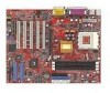
: Line-Out Line-In Mic J10 J3 BIOS VIA KT266A JPW1 AGP Slot PCI Slot 1 Winbond W83697HF PCI Slot 2 PCI Slot 3 Re al Te k ALC650 PCI Slot 4 SFAN1 SW3 VT8235 BATT + J B AT 1 PCI Slot 5 PCI Slot 6 JLED IDE 1 IDE 2 JAUD1 JUSB2 JUSB3 JFP1 JFP2 K7T266 Pro2-U/UL (MS-6593 v1.X) ATX Mainboard - MSI K7T266PRO2-RU | User Guide - Page 11
to adjust the CPU speed through CPU Multiplier and FSB Ø Voltage allows user to adjust the voltage of CPU/Memory/AGP Ø MSI Info provides information about the mainboard, BIOS and OS Ø CPU Info provides detailed information about the CPU Ø CPU Fan Speed shows the current running speed of CPU - MSI K7T266PRO2-RU | User Guide - Page 12
Updates the VGA BIOS online. z Live VGA Driver - Updates the VGA driver online. z Live Utility - Updates the utilities online. If the product you purchased does not support any of the functions listed above, a "sorry" message is displayed. For more information on the update instructions, insert the - MSI K7T266PRO2-RU | User Guide - Page 13
™ The Live Monitor™ is a tool used to schedule the search for the latest BIOS/drivers version on the MSI Web site. To use the function, you need to install the "MSI Live Update 2" application. After installation, the "MSI Live Monitor" icon (as shown on the right) will appear on the screen. Double - MSI K7T266PRO2-RU | User Guide - Page 14
These users can use the feature to detect if there are any problems or failures. D-Bracket™ 2 supports both USB 1.1 & 2.0 spec. D-Bracket™ 2 1 2 3 not installed properly. Decompressing BIOS image to RAM for fast booting. Initializing Keyboard Controller. Testing VGA BIOS - This will start writing - MSI K7T266PRO2-RU | User Guide - Page 15
) Initializing Video Interface - This will start detecting CPU clock, checking type of video onboard. Then, detect and initialize the video adapter. BIOS Sign On - This will start showing information about logo, processor brand name, etc.... Testing Base and Extended Memory - Testing base memory - MSI K7T266PRO2-RU | User Guide - Page 16
MS-6593 ATX Mainboard PC Alert™ 4 The PC AlertTM 4 is a utility you can find in the CD-ROM disk. The utility is just like your PC doctor that can detect the following PC hardware status during real time operation: Ø monitor CPU & system temperatures Ø monitor fan speeds Ø monitor system voltages If - MSI K7T266PRO2-RU | User Guide - Page 17
about the CPU and chipset. Right-click the mouse to select the skin you want to switch to. Cute MSI Reminds You... 1. The new feature COOLER XP will work only if your mainboard supports AMD Athlon XP CPU. 2. Items shown on PC Alert 4 vary depending on your system's status. 3. Whenever the minimum - MSI K7T266PRO2-RU | User Guide - Page 18
how to install the CPU, memory modules, and expansion cards, as well as how to setup the jumpers on the mainboard. Also, it provides the instructions on connecting the peripheral devices, such the mouse, keyboard, etc. While doing the installation, be careful in holding the components and follow the - MSI K7T266PRO2-RU | User Guide - Page 19
MS-6593 ATX Mainboard Quick Components Guide CPU, p.2-3 CFAN1, p.2-9 DDR DIMMs, p.2-5 Back Panel I/O, p.2-7 JWR1, p.2-6 J10, p.2-9 J3, p.2-9 JPW1, p.2-6 JLED, p.2-13 JBAT1, p.2-14 2-2 FDD1, p.2-8 AGP Slot, p.2-15 SFAN1, p.2-9 SW3, p.2-14 PCI Slots, p.2-15 IDE1 - MSI K7T266PRO2-RU | User Guide - Page 20
Hardware Setup Central Processing Unit: CPU The mainboard supports AMD® Athlon™, Athlon™ XP and Duron™ CPU down firmly, and then close the lever to Close Lever complete the installation. MSI Reminds You... Overheating will seriously damage the CPU and system, always make sure the cooling - MSI K7T266PRO2-RU | User Guide - Page 21
information on the proper cooling, you can visit AMD's website for reference. MSI Reminds You... Replacing CPU While replacing the CPU, always turn off the the safety of CPU. Overclocking This motherboard is designed to support overclocking. However, please make sure your components are able to - MSI K7T266PRO2-RU | User Guide - Page 22
Hardware Setup Memory The mainboard provides 2 slots for 184-pin DDR SDRAM DIMM (Double In-Line Memory Module) modules and supports the memory size up to 2GB. You can install PC2100/DDR266 or PC1600/DDR200 modules on the DDR DIMM slots (DDR 1~2). DDR DIMM Slots (DDR 1~2) - MSI K7T266PRO2-RU | User Guide - Page 23
MS-6593 ATX Mainboard Power Supply The mainboard supports ATX power supply for the power system. Before inserting the power supply connector, always make sure that all components are installed properly to ensure that - MSI K7T266PRO2-RU | User Guide - Page 24
LAN Mouse (Optional) Back Panel Parallel Hardware Setup Midi/Joystick Keyboard USB COM A COM B L-out L-in MIC Mouse Connector Pin6 NC Pin5 Mouse Clock Midi/Joystick Pin4 VCC Pin3 GND Pin2 NC Pin1 Mouse DATA Keyboard Connector Pin6 NC Pin5 KBD Clock Audio Ports Pin4 VCC Pin3 GND - MSI K7T266PRO2-RU | User Guide - Page 25
Drive Connector: FDD1 The mainboard provides a standard floppy disk drive connector that supports 360K, 720K, 1.2M, 1.44M and 2.88M floppy disk types. connect up to four hard disk drives, CDROM, 120MB Floppy (reserved for future BIOS) and other devices. FDD1 IDE 1 IDE 2 IDE1 (Primary IDE Connector) - MSI K7T266PRO2-RU | User Guide - Page 26
SFAN1 The CFAN1 (processor fan) and SFAN1 (system fan) support system cooling fan with +12V. Chassis Intrusion Switch Connector: and show a warning message on the screen. To clear the warning, you must enter the BIOS utility and clear the record. CD-In Connector: J10 The connector is for CD-ROM audio - MSI K7T266PRO2-RU | User Guide - Page 27
front panel connectors for electrical connection to the front panel switches and LEDs. JFP1 is compliant with Intel® Front Panel I/O Connectivity Design Guide. Power Power LED Switch JFP1 2 1 10 9 HDD Reset LED Switch Speaker JFP2 2 1 8 7 Power LED 2-10 JFP1 Pin Definition PIN SIGNAL - MSI K7T266PRO2-RU | User Guide - Page 28
and is compliant with Intel® Front Panel I/O Connectivity Design Guide. 2 10 1 9 JAUD1 Pin Definition PIN SIGNAL audio signal to front panel 10 AUD_RET_L Left channel audio signal return from front panel MSI Reminds You... If you don't want to connect to the front audio header, - MSI K7T266PRO2-RU | User Guide - Page 29
/JUSB3 The mainboard provides two USB 2.0 pin headers JUSB2 & JUSB3 (optional USB 2.0 bracket available) that are compliant with Intel® I/O Connectivity Design Guide. USB 2.0 technology increases data transfer rate up to a maximum throughput of 480Mbps, which is 40 times faster than USB 1.1, and is - MSI K7T266PRO2-RU | User Guide - Page 30
with a JLED connector for you to connect to DBracket™ 2. D-Bracket™ 2 is a USB Bracket that supports both USB1.1 & 2. 0 spec. It integrates four LEDs and allows users to identify system problem through 16 various combinations of LED signals. For definitions of 16 signal combinations, please refer to - MSI K7T266PRO2-RU | User Guide - Page 31
This jumper provides 100MHz and 133MHz Front Side Bus frequency selection. 1 JBAT1 1 SW3 1 1 1 1 3 Keep Data 3 Clear Data 3 FSB = 133MHz 3 FSB = 100MHz MSI Reminds You... You can clear CMOS by shorting 2-3 pin while the system is off. Then return to 1-2 pin position. Avoid clearing the - MSI K7T266PRO2-RU | User Guide - Page 32
Hardware Setup Slots The motherboard provides one AGP slot and six 32-bit PCI bus slots. AGP Slot PCI Slots PCI Interrupt Request Routing The IRQ, acronym of interrupt request line and pronounced I-R-Q, are hardware lines over which devices can send interrupt signals to the microprocessor. The PCI - MSI K7T266PRO2-RU | User Guide - Page 33
This chapter provides information on the BIOS Setup program and allows you to configure the system for optimum use. You may need to run the Setup program when: ” An error message appears - MSI K7T266PRO2-RU | User Guide - Page 34
simultaneously pressing , , and keys. Selecting the First Boot Device You are allowed to select the 1st boot device without entering the BIOS setup utility by pressing . When the same message as listed above appears on the screen, press to trigger the boot menu. The - MSI K7T266PRO2-RU | User Guide - Page 35
Decrease the numeric value or make changes Restore the previous CMOS value from CMOS, only for Option Page Setup Menu Load High Performance Defaults Load BIOS Setup Defaults Save all the CMOS changes and exit Getting Help After entering the Setup utility, the first screen you see is the Main Menu - MSI K7T266PRO2-RU | User Guide - Page 36
menu. Standard CMOS Features Use this menu for basic system configurations, such as time, date etc. Advanced BIOS Features Use this menu to setup the items of AMI® special enhanced features. Advanced Chipset Features Use PNP/PCI Configurations This entry appears if your system supports PnP/PCI. 3-4 - MSI K7T266PRO2-RU | User Guide - Page 37
values for the best system performance, but the system stability may be affected. Load BIOS Setup Defaults Use this menu to load factory default settings into the BIOS for stable system performance operations. Save & Exit Setup Save changes to CMOS and exit setup. Exit Without Saving Abandon all - MSI K7T266PRO2-RU | User Guide - Page 38
floppy drives installed. Boot Sector Virus Protection The item is to set the Virus Warning feature for IDE Hard Disk boot sector protection. When Enabled, BIOS will issue a virus warning message and beep if a write to the boot sector or the partition table of the HDD is attempted. Setting options - MSI K7T266PRO2-RU | User Guide - Page 39
Setup Advanced BIOS Features Quick Boot Setting the item to Enabled allows the system to boot within 5 seconds since it will skip some check items. Available options: Enabled, - MSI K7T266PRO2-RU | User Guide - Page 40
MS-6593 ATX Mainboard MSI Reminds You... Available settings for "1st/2nd/3rd Boot Device" floppy drives A: and B:. Floppy Drive Seek This setting causes the BIOS to search for floppy disk drives at boot time. When enabled, the BIOS will activate the floppy disk drives during the boot process. The - MSI K7T266PRO2-RU | User Guide - Page 41
cache (also known as L1 or level 1 cache). Setting to WriteBack will speed up the system performance. System BIOS Cacheable Selecting Enabled allows caching of the system BIOS ROM at F0000hFFFFFh, resulting in better system performance. However, if any program writes to this memory area, a system - MSI K7T266PRO2-RU | User Guide - Page 42
the APIC (Advanced Programmable Interrupt Controller). Due to compliance to PC2001 design guide, the system is able to run in APIC mode. Enabling APIC used for the operating system. You need to select the MPS version supported by your operating system. To find out which version to use, consult the - MSI K7T266PRO2-RU | User Guide - Page 43
BIOS Setup Advanced Chipset Features MSI Reminds You... Change these settings only if you are familiar with the chipset. DRAM Timing Control Press and the following sub-menu appears. Current Host Clock This item shows the current CPU frequency. 3-11 - MSI K7T266PRO2-RU | User Guide - Page 44
RAS Pulse Width, RAS to CAS Delay and SDRAM Bank Interleave automatically to be determined by BIOS based on the configurations on the SPD. Selecting User allows users to configure these fields manually. SDRAM Frequency Use this item to configure the clock frequency of the installed SDRAM. SDRAM CAS - MSI K7T266PRO2-RU | User Guide - Page 45
BIOS Setup SDRAM Burst Length This setting Fast Command This item controls the internal timing of CPU. Selecting Ultra allows CPU to handle data/instructions at the fastest speed. Fast enables CPU to handle at a faster speed, while Normal let Auto. Select 4x only if your AGP card supports it. 3-13 - MSI K7T266PRO2-RU | User Guide - Page 46
Manual allows you to select an AGP driving force in Manual AGP Comp. Driving. It is strongly recommended to select Auto to avoid causing any system error. Manual The chipset has an embedded 32-bit posted write buffer to support delayed transactions cycles so that transactions to and from the ISA - MSI K7T266PRO2-RU | User Guide - Page 47
call VGA BIOS to initialize the VGA card when system wakes up (resumes) from S3 sleep state. The system resume time is shortened when you disable the function, but system will need an AGP driver to initialize the VGA card. Therefore, if the AGP driver of the card does not support the initialization - MSI K7T266PRO2-RU | User Guide - Page 48
the CPU shut off. Display Activity These items specify if the BIOS will monitor the activity of the specified hardware peripheral or component. will be activated. This helps you to prevent the CPU overheating problem. Power Button Function This feature sets the function of the power button - MSI K7T266PRO2-RU | User Guide - Page 49
BIOS Setup interrupt occurs. Setting to Last State will restore the system awakened from power saving modes when activity or input signal of the specified hardware peripheral or component is detected. MSI Reminds You... 1. For "Wake-Up Key" function, the option "Specific Key" refers to the password - MSI K7T266PRO2-RU | User Guide - Page 50
will initialize all the PnP cards. Clear NVRAM The ESCD (Extended System Configuration Data) NVRAM (Non-volatile Random Access Memory) is where the BIOS stores resource information for both PNP and non-PNP devices in a bit string format. When the item is set to Yes, the system will reset - MSI K7T266PRO2-RU | User Guide - Page 51
Integrated Peripherals BIOS Setup FDC Function This is used to enable or disable the onboard Floppy controller. Serial Port 1/2 These Parallel Port IRQ When OnBoard Parallel Port is set to Auto, the item shows Auto indicating that BIOS determines the IRQ for the parallel port automatically. 3-19 - MSI K7T266PRO2-RU | User Guide - Page 52
to All Device if you need to use any USB device in the operating system that does not support or have any USB driver installed, such as DOS and SCO Unix. Set to No Mice only if you want to use any USB device other than the USB mouse. - MSI K7T266PRO2-RU | User Guide - Page 53
PC Health Status BIOS Setup Chassis Intrusion The field enables or disables the feature of recording the chassis intrusion status and issuing a warning message if the chassis is once - MSI K7T266PRO2-RU | User Guide - Page 54
MS-6593 ATX Mainboard Frequency/Voltage Control Spread Spectrum When the motherboard's clock generator pulses, the extreme values (spikes) of the pulses creates EMI (Electromagnetic Interference). The Spread Spectrum function reduces the EMI generated by modulating the pulses. Remember to disable - MSI K7T266PRO2-RU | User Guide - Page 55
the setup menu while User can only enter but do not have the right to change the settings of the setup menu. Load High Performance/BIOS Setup Defaults The High Performance Defaults are the values set by the mainboard manufacturer for the best system performance but probably will cause a stability - MSI K7T266PRO2-RU | User Guide - Page 56
4- or 6-Channel Audio Function Appendix: Using 4- or 6-Channel Audio Function The motherboard is equipped with Realtek ALC650 chip, which provides support for 6-channel audio output, including 2 Front, 2 Rear, 1 Center and 1 Subwoofer channel. ALC650 allows the board to attach 4 or 6 speakers for - MSI K7T266PRO2-RU | User Guide - Page 57
the CD-ROM drive. The CD will run automatically and the setup screen will appear. 2. Click Avance ALC650 Sound Drivers and follow the on-screen instructions to complete the installation. 3. After completion of the installation, please restart your computer. Using 4- or 6-Channel Audio Function In - MSI K7T266PRO2-RU | User Guide - Page 58
Using 4- or 6-Channel Audio Function A-3 - MSI K7T266PRO2-RU | User Guide - Page 59
MS-6593 ATX Mainboard Connecting the Speakers When you have set the Multi-Channel Audio Function mode properly in the software utility, connect your speakers to the correct phonejacks in accordance with the setting in software utility. 2-Channel Mode for Stereo-Speaker Output Refer to the following - MSI K7T266PRO2-RU | User Guide - Page 60
Using 4- or 6-Channel Audio Function 6-Channel Mode for 6-Speaker Output Refer to the following diagram and caption for the founction of each jack on the back panel when 6-Channel Mode is selected. 1 Line Out (Front channels) 2 2 * Line Out (Rear channels) 3 * Line Out (Center and 3 Subwoofer - MSI K7T266PRO2-RU | User Guide - Page 61
The following window appears. Select the speaker which you want to test by clicking it. Subwoofer Front Left Front Right Rear Left Rear Right Center MSI Reminds You... 6 speakers appear on the "Speaker Test" window only when you select "6 channels mode" in the "No. of Speakers" column. If you - MSI K7T266PRO2-RU | User Guide - Page 62
Using 4- or 6-Channel Audio Function 4. While you are testing the speakers in 6-Channel mode, if the sound coming from the center speaker and subwoofer is swapped, you should select Swap Center/Subwoofer Output to readjust these two channels. Select this function A-7 - MSI K7T266PRO2-RU | User Guide - Page 63
MS-6593 ATX Mainboard Playing KaraOK The KaraOK function will automatically remove human voice (lyrics) and leave melody for you to sing the song. This function applies only to 2channel audio operation, so make sure "2-Channel Mode" is selected in the "No. of Speakers" column before playing KaraOK.
-
 1
1 -
 2
2 -
 3
3 -
 4
4 -
 5
5 -
 6
6 -
 7
7 -
8
-
9
-
10
-
11
-
12
-
13
-
14
-
15
-
16
-
17
-
18
-
19
-
20
-
21
-
22
-
23
-
24
-
25
-
26
-
27
-
28
-
29
-
30
-
31
-
32
-
33
-
34
-
35
-
36
-
37
-
38
-
39
-
40
-
41
-
42
-
43
-
44
-
45
-
46
-
47
-
48
-
49
-
50
-
51
-
52
-
53
-
54
-
55
-
56
-
57
-
58
-
59
-
60
-
61
-
62
-
63
 |
 |

K7T266 Pro2-U/UL
Version 1.2
G52-M6593X5
MS-6593 (v1.X) ATX Mainboard