MSI Z490-A PRO User Manual
MSI Z490-A PRO Manual
 |
View all MSI Z490-A PRO manuals
Add to My Manuals
Save this manual to your list of manuals |
MSI Z490-A PRO manual content summary:
- MSI Z490-A PRO | User Manual - Page 1
Quick Start Thank you for purchasing the MSI® Z490-A PRO motherboard. This Quick Start section provides demonstration diagrams about how to install your computer. Some of the installations also provide video demonstrations. Please link to the - MSI Z490-A PRO | User Manual - Page 2
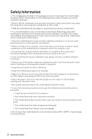
adhere to the following instructions to ensure successful motherboard checked by service personnel: ▪▪Liquid has penetrated into the computer. ▪▪The motherboard has been exposed to moisture. ▪▪The motherboard does not work well or you can not get it work according to user guide. ▪▪The motherboard - MSI Z490-A PRO | User Manual - Page 3
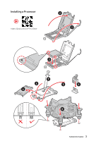
Installing a Processor ⚽ ⚽ https://youtu.be/4ce91YC3Oww 2 1 3 7 4 5 9 6 8 Safety Information 3 - MSI Z490-A PRO | User Manual - Page 4
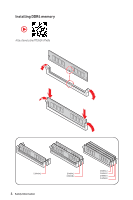
Installing DDR4 memory ⚽ ⚽ http://youtu.be/T03aDrJPyQs DIMMA2 4 Safety Information DIMMA2 DIMMB2 DIMMA1 DIMMA2 DIMMB1 DIMMB2 - MSI Z490-A PRO | User Manual - Page 5
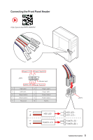
Connecting the Front Panel Header http://youtu.be/DPELIdVNZUI POPWOEWRELREHLDD-EDDL+ED RESET SW POWER SW Power LED Power Switch - -+ -- ++ JFP1 2 1 + 10 9 Reserved HDD LED Reset Switch 1 HDD LED + 2 3 HDD LED - 4 5 Reset Switch 6 7 Reset Switch 8 9 Reserved 10 Power LED + - MSI Z490-A PRO | User Manual - Page 6
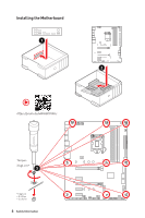
Installing the Motherboard 1 2 ⚽ ⚽ https://youtu.be/wWI6Qt51Wnc Torque: 3 kgf·cm* 3 *3 kgf·cm = 0.3 N·m = 2.6 lbf·in 6 Safety Information - MSI Z490-A PRO | User Manual - Page 7
Connecting the Power Connectors ⚽ ⚽ http://youtu.be/gkDYyR_83I4 ATX_PWR1 CPU_PWR2 CPU_PWR1 Safety Information 7 - MSI Z490-A PRO | User Manual - Page 8
Installing SATA Drives http://youtu.be/RZsMpqxythc 2 1 3 5 4 8 Safety Information - MSI Z490-A PRO | User Manual - Page 9
Installing a Graphics Card http://youtu.be/mG0GZpr9w_A 1 3 2 5 4 6 Safety Information 9 - MSI Z490-A PRO | User Manual - Page 10
Connecting Peripheral Devices 10 Safety Information - MSI Z490-A PRO | User Manual - Page 11
Power On 1 2 3 4 Safety Information 11 - MSI Z490-A PRO | User Manual - Page 12
Panel Header 5 Installing the Motherboard 6 Connecting the Power Slots 28 M2_1~2: M.2 Slots (Key M 29 SATA1~6: SATA 6Gb/s Connectors 31 JFP1, JFP2: Front Panel Connectors 32 JCOM1: Serial Port Connector 32 CPU_PWR1~2, ATX_PWR1: Power Connectors 33 JAUD1: Front Audio Connector 34 JUSB5: USB - MSI Z490-A PRO | User Manual - Page 13
RGB LED connectors 42 Onboard LEDs...43 EZ Debug LED...43 LED_SW1: EZ LED Control 43 Installing OS, Drivers & Utilities 44 Installing Windows® 10 44 Installing Drivers 44 Installing Utilities 44 UEFI BIOS...45 BIOS Setup...46 Entering BIOS Setup 46 Resetting BIOS...47 Updating BIOS - MSI Z490-A PRO | User Manual - Page 14
(from PCH) ∙∙1x HDMI port, supports a maximum resolution of 4096x2160 @ 30Hz ∙∙1x DisplayPort port supports a maximum resolution of 4096 x 2304 @ 60Hz Supports 2-Way AMD® CrossFire™ Technology Intel® Z490 Chipset ∙∙6x SATA 6Gb/s ports* ∙∙2x M.2 slots (Key M) ▪▪M2_1 supports up to PCIe 3.0 x4 and - MSI Z490-A PRO | User Manual - Page 15
10 for SATA storage devices ∙∙Supports RAID 0 and RAID 1 for M.2 PCIe storage devices 1x Realtek® RTL8125B-CG 2.5G LAN Controller ∙∙Intel® Z490 Chipset ▪▪2x USB 3.2 Gen 2 10Gbps ports (1 Type-A port and 1 Type-C port on the back panel) ▪▪7x USB 3.2 Gen 1 5Gbps ports (2 Type-A ports on the back panel - MSI Z490-A PRO | User Manual - Page 16
BIOS Features ∙∙1x 24-pin ATX main power connector ∙∙1x 8-pin ATX 12V power connector ∙∙1x 4-pin ATX 12V power connector ∙∙6x SATA 6Gb/s connectors ∙∙1x USB 3.2 Gen 1 5Gbps Type-C port ∙∙2x USB 3.2 Gen 1 5Gbps connectors (support additional 4 USB 3.2 Gen 1 5Gbps ports) ∙∙2x USB 2.0 connectors - MSI Z490-A PRO | User Manual - Page 17
User Scenario ∙∙ Monitor(Hardware Monitor) ∙∙True Color ∙∙Live Update ∙∙DPC Latency tuner ∙∙Speed Up Please refer to http://download.msi. com/manual/mb/DRAGONCENTER2. pdf for more details. ∙∙Smart Tool ∙∙Super Charger ∙∙ Audio ▪▪Audio Boost ∙∙ Network ▪▪2.5G LAN ▪▪LAN Manager ∙∙ Cooling - MSI Z490-A PRO | User Manual - Page 18
▪▪EZ DEBUG LED ∙∙ Performance ▪▪Multi GPU-CrossFire Technology ▪▪DDR4 Boost ▪▪Core Boost ▪▪Creator Genie ▪▪USB 3.2 Gen 2 10G ▪▪USB with type A+C ▪▪Front USB type-C ▪▪Dual CPU Power ∙∙ Protection ▪▪PCI-E Steel Armor ▪▪PCI-E Steel Slot ∙∙ Experience ▪▪DRAGON CENTER ▪▪Click BIOS 5 18 Specifications - MSI Z490-A PRO | User Manual - Page 19
Package contents Please check the contents of your motherboard package. It should contain: Motherboard Z490-A PRO Case stand-off notification 1 Documentation Quick installation guide 1 Application Driver DVD 1 Cables SATA 6G cables (2 cables/pack) 1 Case badge 1 Accessories Product - MSI Z490-A PRO | User Manual - Page 20
Diagram Processor 2 Channel DDR4 Memory PCI Express Bus 1x SATA 6Gb/s 1x M.2 Switch 2x SATA 6Gb/s 1x M.2 3x SATA 6Gb/s Switch 2x USB 3.2 Gen 2 6x USB 2.0 DMI 3.0 PCH NUVOTON 6687 Realtek ALC892 Rear Audio Jacks 3x PCIe x1 slots Realtek LAN RTL8125B 7x USB 3.2 Gen 1 20 Block Diagram - MSI Z490-A PRO | User Manual - Page 21
Rear I/O Panel PS/2 Combo port Audio Ports 2.5Gbps LAN USB 3.2 Gen 2 10Gbps Type A USB 2.0 Type-A USB 3.2 Gen 2 10Gbps Type C DisplayPort USB 3.2 Gen 1 5Gbps Type A LAN Port LED Status Table Link/ Activity LED Status Off Yellow Blinking Description No link Linked Data activity Speed LED - MSI Z490-A PRO | User Manual - Page 22
Realtek Audio Console After Realtek Audio Console is installed. You can use it to change sound settings to get better sound experience. Application Enhancement Device Selection Main Volume Connector Settings Jack Status ∙∙ Device Selection - allows you to select a audio output source to change - MSI Z490-A PRO | User Manual - Page 23
Audio jacks to headphone and microphone diagram Audio jacks to stereo speakers diagram AUDIO INPUT Audio jacks to 7.1-channel speakers diagram AUDIO INPUT Front Center/ Subwoofer Rear Side Rear I/O Panel 23 - MSI Z490-A PRO | User Manual - Page 24
Overview of Components CPU_PWR1 CPU_PWR2 CPU Socket DIMMB1 DIMMA2 DIMMB2 DIMMA1 JRAINBOW1 CPU_FAN1 PUMP_FAN1 SYS_FAN6 ATX_PWR1 SYS_FAN1 M2_1 PCI_E1 PCI_E2 JBAT JCI1 PCI_E3 PCI_E4 M2_2 PCI_E5 JTBT1 JAUD1 JRGB1 SATA6 JT1 SATA5 SYS_FAN2 SYS_FAN3 JTPM1 JUSB1 LED_SW1 JUSB2 JCOM1 JFP2 - MSI Z490-A PRO | User Manual - Page 25
Type Fan Connectors Power Connectors LGA 1200 CPU Socket Memory slots Front Audio Connector Clear CMOS (Reset BIOS) Jumper Chassis Intrusion Connector Serial Port Connector Front Panel Connectors Addressable RGB LED connectors RGB LED connector Intel RTD3 Connector Thunderbolt Add-on Card Connector - MSI Z490-A PRO | User Manual - Page 26
installing the processor. MSI will deal with Return Merchandise Authorization (RMA) requests if only the motherboard comes with the protective motherboard is designed to support overclocking. Before attempting to overclock, please make sure that all other system components can tolerate overclocking - MSI Z490-A PRO | User Manual - Page 27
modules in the DIMMA2 slot first. ∙∙To overclocking due to the memory frequency operates dependent on its Serial Presence Detect (SPD). Go to BIOS overclocking. ∙∙The stability and compatibility of installed memory module depend on installed CPU and devices when overclocking. ∙∙Please refer www.msi - MSI Z490-A PRO | User Manual - Page 28
3.0 x1 (PCH) ⚠⚠Important ∙∙If you install a large and heavy graphics card, you need to use a tool such as MSI Gaming Series Graphics Card Bolster to support its weight to prevent deformation of the slot. ∙∙For a single PCIe x16 expansion card installation with optimum performance, using the PCI_E1 - MSI Z490-A PRO | User Manual - Page 29
learn how to Install M.2 module. M2_1 http://youtu.be/JCTFABytrYA M2_2 ⚠⚠Important ∙∙Intel® RST only supports PCIe M.2 SSD with UEFI ROM. ∙∙Intel® Optane™ Memory Ready for all M.2 slots. Installing M.2 module 1. Loosen the screws of M.2 SHIELD FROZR heatsink. (For installing M.2 module to M2_2 - MSI Z490-A PRO | User Manual - Page 30
3. Move the position of the standoffs according to your M.2 SSDs length if need. 4. Insert your M.2 SSD into the M.2 slot at a 30-degree angle. 5. Secure the M.2 SSD in place with the supplied M.2 8.5H screw. 8.5H screw 5 Standoff 3 4 30º 6. Put the M.2 SHIELD FROZR heatsink back in - MSI Z490-A PRO | User Manual - Page 31
6Gb/s Connectors These connectors are SATA 6Gb/s interface ports. Each connector can connect to one SATA device. the flat connector be connected to the motherboard for space saving purposes. ∙∙SATA2 will be unavailable when installing M.2 SATA SSD in the M2_1 slot. ∙∙SATA5 & SATA6 will be - MSI Z490-A PRO | User Manual - Page 32
Reset Switch 8 9 Reserved 10 Power LED + Power LED Power Switch Power Switch No Pin JCOM1: Serial Port Connector This connector allows you to connect the optional serial port with bracket. 2 10 1 9 1 DCD 2 SIN 3 SOUT 4 DTR 5 Ground 6 DSR 7 RTS 8 CTS 9 RI 10 No Pin 32 - MSI Z490-A PRO | User Manual - Page 33
CPU_PWR1~2, ATX_PWR1: Power Connectors These connectors allow you to connect an ATX power supply. 8 5 CPU_PWR1 4 1 1 Ground 5 2 Ground 6 3 Ground 7 4 Ground 8 +12V +12V +12V to a proper ATX power supply to ensure stable operation of the motherboard. Overview of Components 33 - MSI Z490-A PRO | User Manual - Page 34
Connector This connector allows you to connect USB 3.2 Gen 1 Type-C connector on the front panel. The connector possesses a foolproof design. When you connect the cable, be sure to connect it with the corresponding orientation. JUSB5 USB Type-C Cable USB Type-C port on the front panel 34 Overview - MSI Z490-A PRO | User Manual - Page 35
3.2 Gen 1 Connectors These connectors allow you to connect USB 3.2 Gen 1 5Gbps ports on the front panel. 10 11 1 20 1 Power 11 2 USB3_RX_DN 12 3 USB3_RX_DP 13 4 Ground 14 5 USB3_TX_C_DN 15 6 USB3_TX_C_DP 16 7 Ground 17 8 USB2.0- 18 9 USB2.0+ 19 - MSI Z490-A PRO | User Manual - Page 36
. ∙∙In order to recharge your iPad,iPhone and iPod through USB ports, please install MSI® DRAGON CENTER utility. JTPM1: TPM Module Connector This connector is for TPM (Trusted Platform Module). Please refer to the TPM security platform manual for more details and usages. 2 12 1 11 1 SPI Power - MSI Z490-A PRO | User Manual - Page 37
fan connectors control fan speed by changing voltage. You can follow the instruction below to adjust the fan connector to PWM or DC Mode. Default You can switch between PWM mode and DC mode and adjust fan speed in BIOS > HARDWARE MONITOR. Select PWM mode or DC mode There are gradient points of - MSI Z490-A PRO | User Manual - Page 38
is opened again, a warning message will be displayed on screen when the computer is turned on. Resetting the chassis intrusion warning 1. Go to BIOS > SETTINGS > Security > Chassis Intrusion Configuration. 2. Set Chassis Intrusion to Reset. 3. Press F10 to save and exit and then press the Enter key - MSI Z490-A PRO | User Manual - Page 39
. 1 1 FORCE_PWR 2 3 SLP_S3# 4 5 GND SCI_EVENT SLP_S5# JRTD3: Intel RTD3 Connector This connector allows you to connect the RTD3 connector on the add-on Thunderbolt I/O card that supports RTD3. 1 1 WAKE 2 PWR EN 3 GND Overview of Components 39 - MSI Z490-A PRO | User Manual - Page 40
that is external powered from a battery located on the motherboard to save system configuration data. If you want to clear the system configuration, set the jumpers to clear the CMOS memory. Keep Data (default) Clear CMOS/ Reset BIOS Resetting BIOS to default values 1. Power off the computer and - MSI Z490-A PRO | User Manual - Page 41
The JRGB connector supports up to 2 meters continuous 5050 RGB LED strips (12V/G/R/B) with the maximum power rating of 3A (12V). ∙∙Always turn off the power supply and unplug the power cord from the power outlet before installing or removing the RGB LED strip. ∙∙Please use MSI's software to control - MSI Z490-A PRO | User Manual - Page 42
3A (5V). In the case of 20% brightness, the connector supports up to 200 LEDs. ∙∙Always turn off the power supply and unplug the power cord from the power outlet before installing or removing the RGB LED strip. ∙∙Please use MSI's software to control the extended LED strip. 42 Overview of Components - MSI Z490-A PRO | User Manual - Page 43
Onboard LEDs EZ Debug LED These LEDs indicate the debug status of the motherboard. CPU - indicates CPU is not detected or fail. DRAM - indicates DRAM is not detected or LED Control This switch is used to switch on/ off all the LEDs of motherboard. LED_OFF LED_SW1 LED_ON (Default) Onboard LEDs 43 - MSI Z490-A PRO | User Manual - Page 44
Press any key to boot from CD or DVD... message. 7. Follow the instructions on the screen to install Windows® 10. Installing Drivers 1. Start up your computer in Windows® 10. 2. Insert MSI® USB Drive into the USB port. 3. Click the Select to choose what happens with this disc pop-up notification - MSI Z490-A PRO | User Manual - Page 45
BIOS MSI UEFI BIOS is compatible with UEFI (Unified Extensible Firmware Interface) architecture. The UEFI BIOS firmware infrastructure has many new functions and advantages that traditional BIOS cannot achieve. It will fully support operating system - this motherboard supports only 64-bit Windows 10 - MSI Z490-A PRO | User Manual - Page 46
may vary from the product you purchased. ∙∙The BIOS items will vary with the processor. Entering BIOS Setup Press Delete key, when the Press DEL key mode F8: Load Overclocking Profile F9: Save Overclocking Profile F10: Save Change and Reset* F12: Take a screenshot and save it to USB flash drive (FAT - MSI Z490-A PRO | User Manual - Page 47
Before updating: Please download the latest BIOS file that matches your motherboard model from MSI website. And then save the BIOS file into the USB flash drive. Updating BIOS: 1. Insert the USB flash drive that contains the update file into the USB port. 2. Please refer the following methods to - MSI Z490-A PRO | User Manual - Page 48
and the internet connection is set properly. Updating BIOS: 1. Install and launch MSI DRAGON CENTER and go to Support page. 2. Select Live Update and click on Advance button. 3. Click on Scan button to search the latest BIOS file. 4. Select the BIOS file and click on Download icon to download and - MSI Z490-A PRO | User Manual - Page 49
both of the motherboard and CPU are supporting this function. overclock. This function is only available when the system, memory and CPU are supporting USB flash drive (FAT/ FAT32 format only). ∙∙ Search - click on this tab or the Ctrl+F keys to enter the search page. It allows you to search by BIOS - MSI Z490-A PRO | User Manual - Page 50
the motherboard you purchased. ∙∙ M-Flash - click on this button to enter the M-Flash menu that provides the way to update BIOS with a USB flash drive. ∙∙ Hardware Monitor - click on this button to enter the Hardware Monitor menu that allows you to manually control the - MSI Z490-A PRO | User Manual - Page 51
item to a favorite menu 1. Select a BIOS item not only on BIOS menu but also on search page. 2. Right-click or press F2 key. 3. Choose a favorite page and click on OK. ▪▪To delete a BIOS item from favorite menu 1. Select a BIOS item on favorite menu. 2. Right-click or press F2 key. 3. Choose Delete - MSI Z490-A PRO | User Manual - Page 52
with a USB flash drive. ▪▪OC PROFILE - allows you to manage overclocking profiles. ▪▪HARDWARE MONITOR - allows you to set the speeds of fans and monitor voltages of system. ▪▪BOARD EXPLORER - provides the information of installed devices on this motherboard. ∙∙ Menu display - provides BIOS setting - MSI Z490-A PRO | User Manual - Page 53
of the device and motherboard. ▶▶System Information Shows detailed system information, including CPU type, BIOS version, and Memory ( parameters and behaviors of PCIe, ACPI, integrated peripherals, integrated graphics, USB, power management and Windows . ▶▶PCIe/PCI Sub-system Settings sub- - MSI Z490-A PRO | User Manual - Page 54
USB controller and device function. Press Enter to enter the sub-menu. ▶▶Super IO Configuration sub-menu Sets system Super I/O chip parameters including COM ports is only supported with NVMe BIOS default values or factory default settings into the BIOS and exit the BIOS setup utility with or - MSI Z490-A PRO | User Manual - Page 55
PC manually is only recommended for advanced users. ∙∙Overclocking is not guaranteed, and if done improperly, it could void your warranty or severely damage your hardware. ∙∙If you are unfamiliar with overclocking, we advise you to use CREATOR GENIE function for easy overclocking. ∙∙The BIOS items - MSI Z490-A PRO | User Manual - Page 56
ratio manually. instructions. When set to Auto, BIOS will configure this setting automatically. This item appears when the installed CPU supports overclock the CPU by adjusting this value. Please note that overclocking behavior and stability is not guaranteed. This item appears when a CPU that support - MSI Z490-A PRO | User Manual - Page 57
a CPU that supports this adjustment is installed. ▶▶DRAM Frequency [Auto] Sets the DRAM frequency. Please note the overclocking behavior is not Clear CMOS jumper/ button section to clear the CMOS data, and enter the BIOS to load the default settings.) ▶▶Memory Fast Boot [Auto] * Enables or - MSI Z490-A PRO | User Manual - Page 58
▶▶PCH Voltages control [Auto] These options allow you to set the voltages related to PCH. If set to Auto, BIOS will set these voltages automatically or you can set it manually. ▶▶CPU Memory Changed Detect [Enabled]* Enables or disables the system to issue a warning message during boot when the CPU - MSI Z490-A PRO | User Manual - Page 59
provides the way to update BIOS with a USB flash drive. Please download the latest BIOS file that matches your motherboard model from MSI website, save the BIOS file into your USB flash drive. And then follow the steps below to update BIOS. 1. Insert the USB flash drive that contains the update - MSI Z490-A PRO | User Manual - Page 60
the current overclocking profile. ▶▶OC Profile Load from ROM Load OC profile from BIOS ROM. ▶▶OC Profile Save to USB Save OC profile to the USB flash drive. The USB flash drive should be FAT/ FAT32 format only. ▶▶OC Profile Load from USB Load OC profile from the USB flash drive. The USB flash drive - MSI Z490-A PRO | User Manual - Page 61
Menu This menu allows you to adjust the fan speed manually and monitor CPU/ system voltage. Select a temperature curve full operating speed. ▪▪All Set Default - configures all fans' speeds return the BIOS default values. ▪▪All Set Cancel - discards current changes and restores previous settings for - MSI Z490-A PRO | User Manual - Page 62
the fan speed. Select a fan to be adjusted Duty points ⚠⚠Important The pictures in this section are for reference only and may vary from the motherboard you purchased. 62 UEFI BIOS - MSI Z490-A PRO | User Manual - Page 63
to RAID/ Optane Mode. 4. Skip this step If you are only using SATA storage devices. If you are using NVMe PCIe SSDs, go to BIOS > SETTINGS > Advanced > Integrated Peripherals > M2_x Pcie Storage Remapping and change setting to Enabled. 5. Press F10 to save configuration and exit, and then reboot and - MSI Z490-A PRO | User Manual - Page 64
Creating RAID Volume 1. As previously mentioned, enable Intel(R) Rapid Storage Technology. 2. Enter Create RAID Volume screen. The following screen appears: 3. Specify a Name for RAID volume. 4. Select the RAID Level best suited to your usage model in RAID Level. 5. In the Select Disks field, press - MSI Z490-A PRO | User Manual - Page 65
be lost. ⚠⚠Important If your system currently boots to RAID and you delete the RAID volume, your system will become unbootable. 1. Go to BIOS > SETTING > Advanced > Intel(R) Rapid Storage Technology. 2. Select the RAID volume from the Intel(R) Rapid Storage Technology screen to enter the RAID VOLUME - MSI Z490-A PRO | User Manual - Page 66
Resetting Disks to Non-RAID 1. Go to BIOS > SETTING > Advanced > Intel(R) Rapid Storage Technology. 2. Select the RAID volume from the Intel(R) Rapid Storage Technology screen to enter the RAID VOLUME INFO screen. 3. Select - MSI Z490-A PRO | User Manual - Page 67
Power off. 2. Replace the failed hard drive with a new one that is of equal or greater capacity. 3. Reboot the system and go to BIOS > SETTING > Advanced > Intel(R) Rapid Storage Technology. 4. Select the Degraded RAID volume from the Intel(R) Rapid Storage Technology screen to enter the RAID VOLUME - MSI Z490-A PRO | User Manual - Page 68
previously mentioned, enable Intel(R) Rapid Storage Technology in BIOS. 2. Insert the MSI USB Drive into the optical drive. 3. Click the from the Windows Control Panel, you can still manually execute the DVDSetup. exe from the root path of the MSI USB Drive. 4. Under the Drivers/Software tab, check - MSI Z490-A PRO | User Manual - Page 69
Requirements ∙∙Intel® Optane™ memory ready MSI® motherboards ∙∙Supported 10th Gen, or later, Intel® the M.2 slot. 3. Enable M.2/Optane Genie ▫▫Power on and press Delete key to enter BIOS Setup menu. you can still manually execute the DVDSetup.exe from the root path of the MSI USB Drive. ▫▫Under the - MSI Z490-A PRO | User Manual - Page 70
follow the cautions listed below. ∙∙ DO NOT set the SATA mode back to AHCI in BIOS. ∙∙ DO NOT revert back to older version of the BIOS. ∙∙ DO NOT remove the Intel® Optane™ memory module. ∙∙ DO NOT replace the CPU that is not supported by Intel® Optane™ Memory. 70 Intel® Optane™ Memory Configuration - MSI Z490-A PRO | User Manual - Page 71
® Optane™ memory application (Intel® Rapid Storage Technology). ▫▫Click Yes in the dialog. ▫▫Reboot System. 2. Disable M.2/Optane Genie ▫▫Press Delete key to enter BIOS Setup menu during POST. ▫▫Disable M.2/Optane Genie by clicking M.2/Optane Genie item. ▫▫Click Ok in the dialog. ▫▫Press F10 to save - MSI Z490-A PRO | User Manual - Page 72
USB device is listed in Windows® Device Manager. ∙∙Connect the USB device to other USB port on the motherboard rear IO panel. The computer does not boot after updating the BIOS ∙∙Clear the CMOS. ∙∙Use the secondary BIOS to bootup the system (Only for motherboard with Dual BIOS) 72 Troubleshooting - MSI Z490-A PRO | User Manual - Page 73
energy and, if not installed and used in accordance with the instructions, may cause harmful interference to radio communications. However, there is no European Harmonized Standards. The point of contact for regulatory matters is MSI, MSI-NL Eindhoven 5706 5692 ER Son. B B クラスB VCCI-B - MSI Z490-A PRO | User Manual - Page 74
la communauté européenne. Par conséquent vous pouvez retourner localement ces matériels dans les points de collecte. MSI WEEE 2002/96/EC 13 2005 MSI MSI EC ESPAÑOL MSI como empresa comprometida con la protección del medio ambiente, recomienda: Bajo la directiva 2002/96/EC de la Uni - MSI Z490-A PRO | User Manual - Page 75
più vicino punto di raccolta 日本JIS C 0950材質宣言 JIS C 0950により、2006年7月1 http://www.msi.com/html/popup/csr/cemm_jp.html http://tw.msi.com/html/popup/csr_tw/cemm_jp.html India RoHS This product complies with the "India E-waste (Management and Handling) Rule 2011" and prohibits use of lead, mercury - MSI Z490-A PRO | User Manual - Page 76
If a problem arises with your system and no solution can be obtained from the user guide, please contact your place of purchase or local distributor. Alternatively, please try the following help resources for further guidance. yy Visit the MSI website for technical guide, BIOS updates, driver
-
 1
1 -
 2
2 -
 3
3 -
 4
4 -
 5
5 -
 6
6 -
 7
7 -
8
-
9
-
10
-
11
-
12
-
13
-
14
-
15
-
16
-
17
-
18
-
19
-
20
-
21
-
22
-
23
-
24
-
25
-
26
-
27
-
28
-
29
-
30
-
31
-
32
-
33
-
34
-
35
-
36
-
37
-
38
-
39
-
40
-
41
-
42
-
43
-
44
-
45
-
46
-
47
-
48
-
49
-
50
-
51
-
52
-
53
-
54
-
55
-
56
-
57
-
58
-
59
-
60
-
61
-
62
-
63
-
64
-
65
-
66
-
67
-
68
-
69
-
70
-
71
-
72
-
73
-
74
-
75
-
76
 |
 |
1
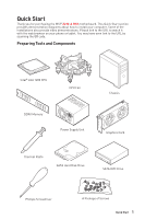
Quick Start
Quick Start
Thank you for purchasing the MSI®
Z490-A PRO
motherboard. This Quick Start section
provides demonstration diagrams about how to install your computer. Some of the
installations also provide video demonstrations. Please link to the URL to watch it
with the web browser on your phone or tablet. You may have even link to the URL by
scanning the QR code.
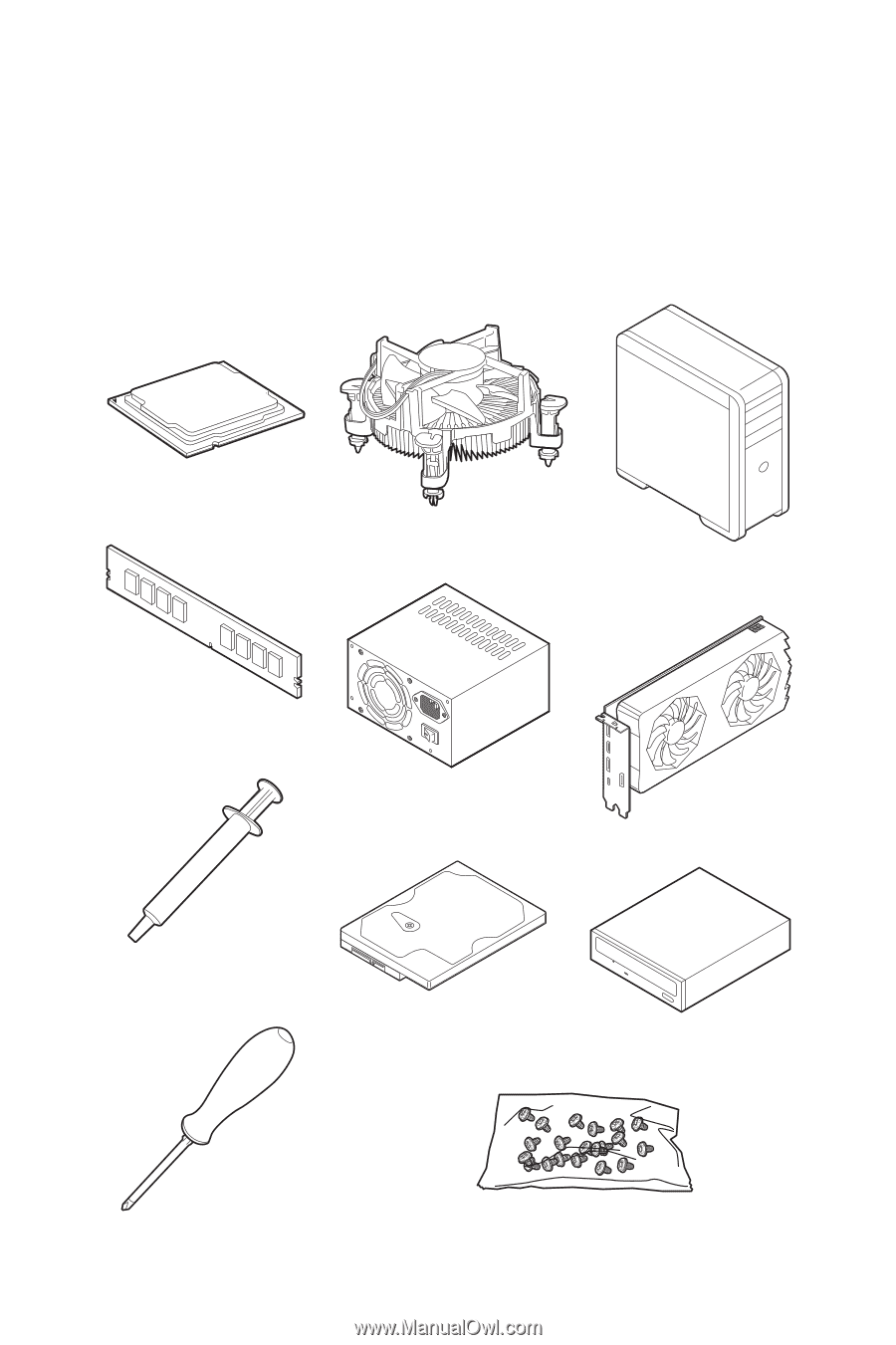
Preparing Tools and Components
Intel® LGA 1200 CPU
CPU Fan
DDR4 Memory
Graphics Card
SATA Hard Disk Drive
SATA DVD Drive
Phillips Screwdriver
Chassis
Power Supply Unit
A Package of Screws
Thermal Paste