Maytag MED5800TW Technical Education
Maytag MED5800TW - Electric Dryer Manual
 |
View all Maytag MED5800TW manuals
Add to My Manuals
Save this manual to your list of manuals |
Maytag MED5800TW manual content summary:
- Maytag MED5800TW | Technical Education - Page 1
ML-4 TECHNICAL EDUCATION CENTENNIAL™ ELECTRIC & GAS DRYERS MODELS: MED5900TW0 MGD5900TW0 MED5800TW0 MGD5800TW0 MED5700TW0 MGD5700TW0 MED5600TW0 MGD5600TW0 MED5500TW0 MGD5500TW0 JOB AID 8178629 - Maytag MED5800TW | Technical Education - Page 2
Maytag Job Aid, "Centennial™ Electric & Gas Dryers" (Part No.8178629), provides the InHome Service Professional with information on the installation, operation, and service of the Centennial™ Electric & Gas Dryers. For specific information on the model being serviced, refer to the "Use and Care Guide - Maytag MED5800TW | Technical Education - Page 3
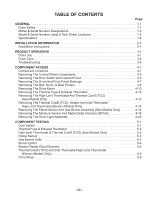
Specifications 1-4 INSTALLATION INFORMATION 2-1 Installation Instructions 2-1 PRODUCT OPERATION 3-1 Dryer Use 3-1 Dryer Care 3-4 Troubleshooting Cutoff (TCO), Heater, And Inlet Thermistor/ High-Limit Thermostat (Electric Models Only 4-14 Removing The Flame Sensor And Gas Burner Assembly - Maytag MED5800TW | Technical Education - Page 4
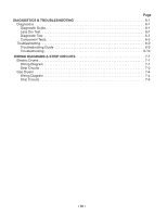
6-1 Less Dry Test 6-1 Diagnostic Test 6-1 Component Tests 6-3 Troubleshooting 6-9 Troubleshooting Guide 6-9 Troubleshooting 6-10 WIRING DIAGRAMS & STRIP CIRCUITS 7-1 Electric Dryers 7-1 Wiring Diagram 7-1 Strip Circuits 7-3 Gas Dryers 7-4 Wiring Diagram 7-4 Strip Circuits 7-6 - iv - - Maytag MED5800TW | Technical Education - Page 5
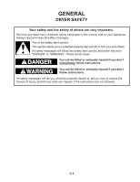
DRYER SAFETY Your safety and the safety of others are very important. We have provided many important safety messages in this manual and if you don't immediately follow instructions. WARNING You can be killed or seriously injured if you don't follow instructions. All safety messages will tell - Maytag MED5800TW | Technical Education - Page 6
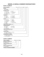
NUMBER DESIGNATIONS MODEL NUMBER MODEL NUMBER M E D 5 9 00 T W 0 BRAND M = Maytag ACCESS / FUEL T = Top Load F = Front Load W = Work Space E = Electric G = Gas H = Horizontal V = Vertical PRODUCT W = Washer D = Dryer T = Thin Twin P = Pedestal B = Combo C = Compact SERIES 1 = Innovation - Maytag MED5800TW | Technical Education - Page 7
MODEL & SERIAL NUMBER LABEL & TECH SHEET LOCATIONS The Model/Serial Number Label and Tech Sheet locations are shown below. Model/Serial Number Label Location Tech Sheet Location (Access Inside Console) 1-3 - Maytag MED5800TW | Technical Education - Page 8
SPECIFICATIONS Model Capacity (cu. ft.) GentIeBreeze™ Drying System Wrinkle Prevent Smooth BaIance™ Suspension DuraCushion™ Dryer Drum Interior Light Spill Guard Reversible Swing Door Commercial-Grade SteelReinforced Baseframe 360° Front & Rear Heat Seal High Torque Motor (1/3-HP) Front Serviceable - Maytag MED5800TW | Technical Education - Page 9
before starting installation. Read and follow the instructions provided with any tools listed here. Electric Models • Flat-blade screwdriver • #2 whom you purchased your dryer. For further information, please refer to the "Assistance or Service" section of the "Use & Care Guide." • Mobile Home - Maytag MED5800TW | Technical Education - Page 10
only). • If you are using a power supply cord, a grounded electrical outlet located within 2 ft (61 cm) of either side of the dryer. See "Electrical Requirements," pages 2-4, 2-6, or 2-14. • A sturdy floor to support the total weight (dryer and load) of 200 lbs. (90.7 kg). The combined weight of - Maytag MED5800TW | Technical Education - Page 11
B. Side view - closet or confined area C. Closet door with vents *Required spacing 3"* (7.6 cm) Mobile Home - Additional Installation Requirements This dryer is suitable for mobile home installations. The installation must conform to the Manufactured Home Construction and Safety Standard, Title 24 - Maytag MED5800TW | Technical Education - Page 12
it is recommended that a qualified electrician determine that the ground path is adequate. Electrical Connection To properly install your dryer, you must determine the type of electrical connection you will be using and follow the instructions provided for it here. • If local codes do not permit the - Maytag MED5800TW | Technical Education - Page 13
5 ft (1.52 m) long. GROUNDING INSTRUCTIONS • For a grounded, cord-connected dryer: This dryer must be grounded. In the event of malfunction or breakdown, grounding will reduce the risk of electric shock by providing a path of least resistance for electric current. This dryer uses a cord having an - Maytag MED5800TW | Technical Education - Page 14
that you use Power Supply Cord Replacement Part Number 3394208. For further information, please reference the service numbers located in the "Assistance or Service" section of the "Use & Care Guide." Electrical Shock Hazard Plug into a grounded 4 prong outlet. Failure to do so can result in death - Maytag MED5800TW | Technical Education - Page 15
DIRECT WIRE WARNING Fire Hazard Use a new UL listed 30 amp power supply cord. Use a UL listed strain relief. Disconnect power before making electrical connections. Connect neutral wire (white or center wire) to center terminal (silver). Ground wire (green or bare wire) must be connected to green - Maytag MED5800TW | Technical Education - Page 16
the strain relief. The strain relief should have a tight fit with the dryer cabinet and be in a horizontal position. Do not further tighten strain relief following instructions for your type of electrical connection: 4-wire (recommended) 3-wire (if 4-wire is not available) Electrical Connection - Maytag MED5800TW | Technical Education - Page 17
screws. 5. Tighten strain relief screws. 6. Insert tab of terminal block cover into slot of dryer rear panel. Secure cover with hold-down screw. 7. You have completed your electrical connection. Now go to "Venting Requirements," page 2-17. E D A. External ground conductor screw - Dotted line - Maytag MED5800TW | Technical Education - Page 18
mobile homes and where local codes do not permit the use of 3-wire connections. Direct wire cable must have 5 ft (1.52 m) of extra length so dryer can be moved if needed. Strip 5˝ (12.7 cm) of outer covering from end of cable, leaving bare ground wire at 5˝ (12.7 cm). Cut 1-1/2˝ (3.8 cm) from - Maytag MED5800TW | Technical Education - Page 19
screw. B C D 5. Tighten strain relief screw. 6. Insert tab of terminal block cover into slot of dryer rear panel. Secure cover with hold-down screw. 7. You have completed your electrical connection. Now go to "Venting Requirements," page 2-17. E A A. Neutral ground wire B. External ground - Maytag MED5800TW | Technical Education - Page 20
4. Tighten strain relief screws. 5. Insert tab of terminal block cover into slot of dryer rear panel. Secure cover with hold-down screw. 6. You have completed your electrical connection. Now go to "Venting Requirements," page 2-17. 3-wire connection: Direct Wire Use where local codes permit - Maytag MED5800TW | Technical Education - Page 21
strain relief screws. 5. Insert tab of terminal block cover into slot of dryer rear panel. Secure cover with hold-down screw. 6. Connect a separate ground conductor screw to an adequate ground. 7. You have completed your electrical connection. Now go to "Venting Requirements," page 2-17. E F - Maytag MED5800TW | Technical Education - Page 22
AC only, 15- or 20-amp, fused electrical supply is required. A timedelay fuse or circuit breaker is recommended. It is recommended that a separate circuit serving only this dryer be provided. GROUNDING INSTRUCTIONS • For a grounded, cord-connected dryer: This dryer must be grounded. In the event of - Maytag MED5800TW | Technical Education - Page 23
of a qualified person include: licensed heating personnel, authorized gas company personnel, and authorized service personnel. Failure to do so can . It is recommended that an individual manual shutoff valve be installed within six (6) feet (1.8 m) of the dryer. The location should be easy to - Maytag MED5800TW | Technical Education - Page 24
Use only pipe-joint compound. Do not use TEFLON®† tape. • This dryer must be connected to the gas supply line with a listed flexible gas m) increase in elevation. Gas Supply Pressure Testing • The dryer must be disconnected from the gas supply piping system during pressure testing at pressures greater - Maytag MED5800TW | Technical Education - Page 25
vent with rigid or flexible heavy metal vent. • Review Vent system chart. Modify existing vent system if necessary Maytag Services. For more information, see the "Assistance or Service" section of the "Use & Care Guide vent must be fully extended and supported when the dryer is in its final position. - Maytag MED5800TW | Technical Education - Page 26
latch. Improper venting can cause moisture and lint to collect indoors, which may result in: • Moisture damage to woodwork, furniture, paint, wallpaper, carpets, etc. • Housecleaning problems and health problems. 2-18 - Maytag MED5800TW | Technical Education - Page 27
or Service" section of the "Use & Care Guide" to order: • Over-the-Top Installation: Part Number 4396028 • Periscope Installation (For use with dryer vent close-clearance installations are shown. Refer to the manufacturer's instructions. A B A. Over-the-top installation (also available with - Maytag MED5800TW | Technical Education - Page 28
vent runs longer than those specified in the Vent system chart. Exhaust systems longer than those specified will: • Shorten the life of the dryer. • Reduce performance, resulting in longer drying times and increased energy usage. The Vent system chart provides venting requirements that will help to - Maytag MED5800TW | Technical Education - Page 29
hood. 2. Connect vent to exhaust hood. Vent must fit inside exhaust hood. Secure vent to exhaust hood with 4˝ (10.2 cm) clamp. 3. Run vent to dryer location. Use the straightest path possible. See "Determine vent path," page 2-20 in "Plan Vent System." Avoid 90° turns. Use clamps to seal all joints - Maytag MED5800TW | Technical Education - Page 30
are no kinks in the flexible gas line. 4. Once the exhaust vent connection is made, remove the corner posts and cardboard. LEVEL DRYER Check the levelness of the dryer. Check levelness first side to side, then front to back. A. Closed valve B. Open valve 4. Test all connections by brushing on an - Maytag MED5800TW | Technical Education - Page 31
between doors. Reattach outer door panel to inner door panel so handle is on the side where hinges were just removed. 7. Attach door hinges to dryer door so that the larger hole is at the bottom of the hinge. 8. Remove door strike (E) from cabinet. Use a small, flat-blade screwdriver to gently - Maytag MED5800TW | Technical Education - Page 32
. Do not use an extension cord. Failure to follow these instructions can result in death, fire, or electrical shock. dryer door and feel for heat. If you feel heat, cancel cycle and close the door. If you do not feel heat, turn off the dryer and check the following: • There may be 2 household fuses - Maytag MED5800TW | Technical Education - Page 33
WARNING Explosion Hazard Keep flammable materials and vapors, such as gasoline, away from dryer. Do not dry anything that has ever had anything flammable on it (even after washing). Failure to follow these instructions can result in death, explosion, or fire. Fire Hazard No washer can completely - Maytag MED5800TW | Technical Education - Page 34
dryer as soon as it stops, wrinkles can form. This feature periodically tumbles, rearranges and fluffs the load without heat to help smooth out wrinkles. 6. (OPTIONAL) Your dryer . See "Dryer Cycle Descriptions" (separate sheet). 8. If desired, add fabric softener sheet. Follow instructions on the - Maytag MED5800TW | Technical Education - Page 35
dried on a clothesline or by using an air cycle. Refer to the following table. 4. Start the dryer. Reset cycle to complete drying, if needed. Rack Dry Washable wool items (block to shape, lay filled Cycle Timed Drying Timed Drying Air (no heat) Temp Low Low N/A Time 60 min. 60 min. 90 min. 3-3 - Maytag MED5800TW | Technical Education - Page 36
with the brush to remove residue buildup. 4. Rinse screen with hot water. Explosion Hazard Keep flammable materials and vapors, such as gasoline, away from dryer. Place dryer at least 18 inches (46 cm) above the floor for a garage installation. Failure to do so can result in death, explosion, or fire - Maytag MED5800TW | Technical Education - Page 37
counterclockwise. Replace the bulb with a 10-watt appliance bulb only. Replace the cover and secure with the screw. 4. Plug in dryer or reconnect power. Electrical Shock Hazard Disconnect power before servicing. Replace all parts and panels before operating. Failure to do so can result in death or - Maytag MED5800TW | Technical Education - Page 38
may not have heat. Electric dryers use 2 household fuses or circuit breakers. Replace the fuse or reset the circuit breaker. If the problem continues, call an is the dryer level front to back and side to side? The dryer may vibrate if not properly installed. See the Installation Instructions. • Is - Maytag MED5800TW | Technical Education - Page 39
have ventilation openings at the top and bottom of the door. The rear of the dryer requires 5˝ (12.7 cm) of airspace, and the sides and front of the dryer require a minimum of 1˝ (2.5 cm). See the Installation Instructions. • Has the air dry cycle been selected? Select the right cycle for the types - Maytag MED5800TW | Technical Education - Page 40
painting, staining or varnishing in the area where your dryer is located? If so, ventilate the area. When the odors or fumes are gone from the area, rewash and dry the clothing. • Is the dryer being used for the first time? The new electric heating element may have an odor. The odor will be - Maytag MED5800TW | Technical Education - Page 41
COMPONENT ACCESS This section instructs you on how to service each component inside the Maytag Centennial™ Electric & Gas Dryers. The components and their locations are shown below. COMPONENT LOCATIONS Electric Dryer Components Electronic Control Wrinkle Prevent Switch DC Heater Relay DC Motor - Maytag MED5800TW | Technical Education - Page 42
cover is facing you, remove the six cover screws, and remove the cover. Electrical Shock Hazard Disconnect power before servicing. Replace all parts and panels before operating. Failure to do so can result in death or electrical shock. 1. Unplug dryer or disconnect power. 2. Turn off gas supply to - Maytag MED5800TW | Technical Education - Page 43
6. To remove the DC motor and DC heater relays: a) Disconnect the wire connectors from the relay terminals. b) Loosen one screw, remove the other screw, and remove the relay from the control panel. (2) RD-BK (DC Mtr.) (2) RD-WH (DC Htr.) (2) BU (DC Mtr.) (2) RD (DC Htr.) d) Unsnap the push to - Maytag MED5800TW | Technical Education - Page 44
9. To remove the control board: a) Disconnect wire connectors PS01 through PS04 from the board terminals. b) Push the end of the locking tab stop from against the control panel, press down on the locking tabs, and remove the control board from the holders. 10. To remove the timer: a) Pull the knob - Maytag MED5800TW | Technical Education - Page 45
: a) Disconnect the door switch connector from the harness connector. Electrical Shock Hazard Disconnect power before servicing. Replace all parts and panels before operating. Failure to do so can result in death or electrical shock. 1. Unplug dryer or disconnect power. 2. Turn off gas supply to - Maytag MED5800TW | Technical Education - Page 46
7. To remove the cabinet front: a) Disconnect the door switch connector from the harness connector. b) Remove the left and right screws from the inside of the cabinet front. Door Switch Connector Cabinet Front Screws c) Pull the cabinet front forward slightly, lift and unhook it from the two bottom - Maytag MED5800TW | Technical Education - Page 47
THE DRUM AND FRONT PANEL BEARINGS WARNING Drum Bearing Locking Tabs Electrical Shock Hazard Disconnect power before servicing. Replace all parts and panels before operating. Failure to do so can result in death or electrical shock. 1. Unplug dryer or disconnect power. 2. Turn off gas supply to - Maytag MED5800TW | Technical Education - Page 48
the drum and remove it with the belt from the dryer. Remove Drum & Belt Electrical Shock Hazard Disconnect power before servicing. Replace all parts and panels before operating. Failure to do so can result in death or electrical shock. 1. Unplug dryer or disconnect power. 2. Turn off gas supply to - Maytag MED5800TW | Technical Education - Page 49
a) Left Roller Only: Remove the support bracket screw, and pull the support bracket and the round press-on nut off the end of the roller shaft. Left Roller b) Push the triangular clip off the grooved slot in - Maytag MED5800TW | Technical Education - Page 50
top tab, and disconnect the wire harness connector from the drive motor. Electrical Shock Hazard Disconnect power before servicing. Replace all parts and panels before operating. Failure to do so can result in death or electrical shock. 1. Unplug dryer or disconnect power. 2. Turn off gas supply to - Maytag MED5800TW | Technical Education - Page 51
7. Place a 13/16˝ wrench on the back of the blower wheel, and a 7/16˝ wrench on the front of the drive motor shaft (flatted). Turn the drive motor shaft to the right (clockwise) and loosen the blower wheel (left-hand thread). 13/16˝ Wrench Blower Wheel Loosen Loosen REASSEMBLY NOTE : When you - Maytag MED5800TW | Technical Education - Page 52
FUSE & EXHAUST THERMISTOR WARNING Electrical Shock Hazard Disconnect power before servicing. Replace all parts and panels before operating. Failure to do so can result in death or electrical shock. 1. Unplug dryer or disconnect power. 2. Turn off gas supply to dryer. 3. Remove the rear panel - Maytag MED5800TW | Technical Education - Page 53
Electrical Shock Hazard Disconnect power before servicing. Replace all parts and panels before operating. Failure to do so can result in death or electrical Screw High-Limit Thermostat 1. Unplug dryer or disconnect power. 2. Turn off gas supply to dryer. 3. Pull the dryer out from the wall so that - Maytag MED5800TW | Technical Education - Page 54
MODELS ONLY) WARNING Thermal Cutoff (TCO) Electrical Shock Hazard Disconnect power before servicing. Replace all parts and panels before operating. Failure to do so can result in death or electrical shock. 1. Unplug dryer or disconnect power. 2. Remove the rear panel (see page 4-13 for the - Maytag MED5800TW | Technical Education - Page 55
d) Remove the two hex-head screws from the heater assembly and remove the assembly. e) Using a flat-blade screwdriver, pry the inlet thermistor terminal off the heater terminal, and remove the thermistor from the assembly. Heater Assembly Screws Heater Assembly Heater Assembly Terminal Pry Tab - Maytag MED5800TW | Technical Education - Page 56
Hazard Disconnect power before servicing. Replace all parts and panels before operating. Failure to do so can result in death or electrical shock. Flame Sensor Screw BU & WH Wires) Burner Venturi 1. Unplug dryer or disconnect power. Tab 2. Turn off gas supply to dryer. 3. Remove the cabinet front - Maytag MED5800TW | Technical Education - Page 57
from the coil terminals. c) Remove the two screws from the bracket, and lift the two coils off their cores. Coil Screws Burner Harness Connector Support Bracket Screw d) Remove the two 5/16˝ hex-head screws from the burner bracket. e) Pull the burner assembly forward, unhook the bracket tabs from - Maytag MED5800TW | Technical Education - Page 58
lint screen air duct. Electrical Shock Hazard Disconnect power before servicing. Replace all parts and panels before operating. Failure to do so can result in death or electrical shock. 1. Unplug dryer or disconnect power. 2. Turn off gas supply to dryer. 3. Open the dryer door. 4. To remove the - Maytag MED5800TW | Technical Education - Page 59
e) Disconnect the two wires from the terminals of the moisture sensor strips. f) Unlock and disconnect the moisture sensor harness connector with the Metal Oxide Varistors (MOVs) from the main harness. Moisture Sensor Strip Terminal Connectors Sensor MOVs Moisture Sensor Harness Connector 4-19 - Maytag MED5800TW | Technical Education - Page 60
Drum Light Holder Screw Electrical Shock Hazard Disconnect power before servicing. Replace all parts and panels before operating. Failure to do so can result in death or electrical shock. 1. Unplug dryer or disconnect power. 2. Turn off gas supply to dryer. 3. Open the dryer door. 4. Remove the - Maytag MED5800TW | Technical Education - Page 61
disconnected. ohms-per-volt DC, or greater. WARNING Electrical Shock Hazard Disconnect power before servicing. Replace all parts and panels before operating. Failure to do so can result in death or electrical shock. DOOR SWITCH 1. Unplug dryer or disconnect power. 2. Turn off gas supply to - Maytag MED5800TW | Technical Education - Page 62
power before servicing. Replace all parts and panels before operating. Failure to do so can result in death or electrical shock. THERMAL limit thermostat and thermal cutoff (TCO). 1. Unplug dryer or disconnect power. 2. Turn off gas supply to dryer. 3. Disconnect the wire connectors from the high- - Maytag MED5800TW | Technical Education - Page 63
Hazard Disconnect power before servicing. Replace all parts and panels before operating. Failure to do so can result in death or electrical shock. FLAME SENSOR GAS BURNER COILS Burner Coils Refer to page 4-16 for the procedure for accessing the flame sensor. 1. Unplug dryer or disconnect power - Maytag MED5800TW | Technical Education - Page 64
servicing. Replace all parts and panels before operating. Failure to do so can result in death or electrical shock. BURNER IGNITOR Burner Ignitor 2-Wire Connector ELECTRIC 4-14 for the procedure for accessing the electric heater. 1. Unplug dryer or disconnect power. 2. Disconnect the wires from - Maytag MED5800TW | Technical Education - Page 65
Shock Hazard Disconnect power before servicing. Replace all parts and panels before operating. Failure to do so can result in death or electrical shock. THERMAL CUTOFF (TCO) AND INLET THERMISTOR/ HIGH-LIMIT THERMOSTAT (ELECTRIC MODELS ONLY) Thermal Cutoff (TCO) Thermal Cutoff (TCO) Inlet Thermistor - Maytag MED5800TW | Technical Education - Page 66
before servicing. Replace all parts and panels before operating. Failure to do so can result in death or electrical shock. DRIVE MOTOR Main Winding: Blue Wire (In Back and Bare) Copper Wire (Pin 5) Connector Refer to page 4-10 for the procedure for accessing the drive motor. 1. Unplug dryer or - Maytag MED5800TW | Technical Education - Page 67
DIAGNOSTICS & TROUBLESHOOTING DIAGNOSTICS WARNING Electrical Shock Hazard Disconnect power before servicing. Replace all parts and panels before operating. Failure to do so can result in death or electrical shock. DIAGNOSTIC GUIDE Before servicing, check the following: • Make sure there is power at - Maytag MED5800TW | Technical Education - Page 68
Activating The Test Mode 1. Set the following configuration: • Door - must be open • Temperature switch - Air Fluff • End of Cycle Signal switch - Louder • Timer - Timed Drying or Sensor Drying selection 2. Turn the Wrinkle Prevent switch from Off to On three times within a five second period. A - Maytag MED5800TW | Technical Education - Page 69
terminal block. See illustration below. Power Cord N Plug Terminal Block L1 COM Plug-to-terminal connections for electric dryer. • If there is no continuity, replace the power cord and test the dryer. • If there is continuity, go to step 4. 4. In a similar way, check which terminal of the plug is - Maytag MED5800TW | Technical Education - Page 70
to determine that the timer motor advances (should run continuously). If the timer does not advance or fails the diagnostic test: 1. Unplug dryer or disconnect power. 3. Access the electronic control without disconnecting any wiring to the control board. 4. With an ohmmeter, check for continuity - Maytag MED5800TW | Technical Education - Page 71
Temperature Switch Table SWITCH CONTACTS POSITION 3-5 2-4 1-4 FUNCTION 12 o'clock O O O Air Fluff, No Heat 2 o'clock O O X Ex-Low 4 o'clock O X O Low 5 o'clock O X Test White-Black Tan-White White 12 4 SIGNAL 1. Unplug dryer or disconnect power. 2. Remove the wires from the switch to - Maytag MED5800TW | Technical Education - Page 72
thermal cut-off and high limit thermostat. In addition, check for failed heat system, or blocked or improper exhaust system. Thermal Fuse Test-Electric A thermal fuse is used on this model. The thermal fuse is wired in series with the dryer drive motor. If the thermal fuse opens, power is shut off - Maytag MED5800TW | Technical Education - Page 73
(63° ± 6°) 10°-15° (6°-8°) Medium, Energy Saver 135° ± 10° below the (57° ± 6°) heat turn off Low 125° ± 10° temperature (52° ± 6°) Ex-Low 115° ± 10° (46° ± the exhaust temperature is not within specified limits: - Unplug dryer or disconnect power. - Disconnect wires from thermistor, then check - Maytag MED5800TW | Technical Education - Page 74
Gas Valve Test 1. Unplug dryer or disconnect power. 2. Remove harness plugs. 3. Use an ohmmeter to determine if a gas valve coil has failed. Measure resistance across terminals. See the illustration. • Readings - Maytag MED5800TW | Technical Education - Page 75
TROUBLESHOOTING TROUBLESHOOTING GUIDE PROBLEM POSSIBLE CAUSE / TEST Refer to Motor Strip Circuit, page 7-3 or 7-6. - SUPPLY CONNECTIONS - HARNESS/CONNECTION - MOTOR RELAY DRYER WILL NOT - PUSH TO START (PTS) SWITCH RUN. - THERMAL FUSE - MOTOR - DOOR SWITCH - ELECTRONIC CONTROL For more - Maytag MED5800TW | Technical Education - Page 76
replace the motor. PROBLEM: Dryer Will Not Heat Electric Only Refer to Heater Strip Circuit, page 7-3; and Troubleshooting Guide, page 6-9. 1. the heat element assembly. 6. Check continuity of motor centrifugal switch: • 1M to 2M terminals should be open the off condition. Manually operating - Maytag MED5800TW | Technical Education - Page 77
Air Fluff. If the dryer still heats: • Unplug dryer or disconnect power. • Replace the electronic control assembly. PROBLEM: Dryer Won't Shut Off Refer to Motor and Moisture Sensor Strip Circuits, page 7-3 or 7-6; and Troubleshooting Guide, page 6-9. 1. With the dryer fully assembled, set the timer - Maytag MED5800TW | Technical Education - Page 78
PROBLEM: Timer Continuously Advances Refer to Timer Drawing, page 7-2 or 7-5; Motor Strip Circuit, page 7-3 or 7-6; and Troubleshooting Guide, page 6-9. 1. Unplug dryer or disconnect power. 2. Verify the Blue wire and the Black L1 wires are in the correct positions. See timer illustration on page - Maytag MED5800TW | Technical Education - Page 79
WIRING DIAGRAMS & STRIP CIRCUITS Electric Dryers WIRING DIAGRAM 7-1 L1 LINE - BK BK DRUM LAMP BK DL 240 VOLTS 120 VOLTS OR R BK TIMER ELECTRONIC CONTROL BK PT-1 TIMER P2-6 DOOR R TCO - Maytag MED5800TW | Technical Education - Page 80
Start Winding Main Winding Black Blue Violet White GreenYellow Red Red Function Start Contacts 1M 2M 3M 5M 6M Run = Contacts closed Centrifugal Switch (Motor) Timer BU BK R V W Wire Colors Blue Black Red Violet White R B B K U PT-1 DATE W V Pluggable Drive Motor Switch Timer - Maytag MED5800TW | Technical Education - Page 81
MOTOR STRIP CIRCUITS L1 LINE - BK TIMER ELECTRONIC CONTROL BK BK PT-1 TIMER P2-6 DOOR BU P1-1 MTR BU BU BK BU NO MOTOR RELAY P3-2 HEATER LOW PK-BK PTS BK COM BU BU-BK P2-7 MOTOR PK-BK START P1-5 START SENSE BU 240 VOLTS 120 VOLTS W - NEUTRAL BU BU W R - LINE L2 DOOR SWITCH - Maytag MED5800TW | Technical Education - Page 82
L1 LINE - BK W - NEUTRAL BK DRUM LAMP 5-15P PLUG G 120 VOLTS BK DL OR W Gas Dryers WIRING DIAGRAM 7-4 TIMER BK BU ELECTRONIC CONTROL BK PT-1 TIMER DOOR P2-6 BU P1-1 MTR V P1-2 T2 R P1-3 T3 W P1-4 T4 MOIST. GND P2-5 G-Y P2-4 Y-R - Maytag MED5800TW | Technical Education - Page 83
Start Winding Main Winding Black Blue Violet White Green/Yellow Red Red Pluggable Drive Motor Switch Contacts Function 1M 2M 3M 5M 6M Start Run = Contacts closed Centrifugal Switch (Motor) Timer BU BK R V W Wire Colors Blue Black Red Violet White R B B K U PT-1 DATE W V Black Blue - Maytag MED5800TW | Technical Education - Page 84
MOTOR STRIP CIRCUITS L1 LINE - BL TIMER BK ELECTRONIC CONTROL BL PT-1 TIMER P2-6 DOOR BU P1-1 MTR 5-15P PLUG G 120 VOLTS BU P3-2 R-W HEATER LOW BK BU PK-BK NO MOTOR RELAY PTS COM P2-7 48 VDC PK-BK MOTOR START BU BU BK P1-5 START SENSE BU-BK BU W - NEUTRAL BU BU W W DOOR - Maytag MED5800TW | Technical Education - Page 85
- NOTES - 7-7 - Maytag MED5800TW | Technical Education - Page 86
- NOTES - 7-8 - Maytag MED5800TW | Technical Education - Page 87
PROFESSIONAL FOR LITERATURE ORDERS: PHONE: 1-800-851-4605 FOR TECHNICAL INFORMATION AND SERVICE POINTERS: www.servicematters.com IN CANADA: FOR PRODUCT SPECIFICATIONS AND WARRANTY INFORMATION CALL: 1-800-461-5681 FOR TECHNICAL ASSISTANCE WHILE AT THE CUSTOMER'S HOME CALL: THE TECHNICAL ASSISTANCE - Maytag MED5800TW | Technical Education - Page 88
-
 1
1 -
 2
2 -
 3
3 -
 4
4 -
 5
5 -
 6
6 -
 7
7 -
8
-
9
-
10
-
11
-
12
-
13
-
14
-
15
-
16
-
17
-
18
-
19
-
20
-
21
-
22
-
23
-
24
-
25
-
26
-
27
-
28
-
29
-
30
-
31
-
32
-
33
-
34
-
35
-
36
-
37
-
38
-
39
-
40
-
41
-
42
-
43
-
44
-
45
-
46
-
47
-
48
-
49
-
50
-
51
-
52
-
53
-
54
-
55
-
56
-
57
-
58
-
59
-
60
-
61
-
62
-
63
-
64
-
65
-
66
-
67
-
68
-
69
-
70
-
71
-
72
-
73
-
74
-
75
-
76
-
77
-
78
-
79
-
80
-
81
-
82
-
83
-
84
-
85
-
86
-
87
-
88
 |
 |
TECHNICAL EDUCATION
JOB AID 8178629
ML-4
ELECTRIC & GAS
DRYERS
MODELS: MED5900TW0
MGD5900TW0
MED5800TW0
MGD5800TW0
MED5700TW0
MGD5700TW0
MED5600TW0
MGD5600TW0
MED5500TW0
MGD5500TW0
CENTENNIAL
™