Maytag MEDC300BW Installation Guide
Maytag MEDC300BW Manual
 |
View all Maytag MEDC300BW manuals
Add to My Manuals
Save this manual to your list of manuals |
Maytag MEDC300BW manual content summary:
- Maytag MEDC300BW | Installation Guide - Page 1
6 Install Leveling Legs 7 Electrical Connection 7 VENTING 13 Venting Requirements 13 Plan Vent System 14 Venting Kits 14 Install Vent System 16 Connect Vent 16 Level Dryer 16 Complete Installation Checklist 16 Reverse Door Swing (Optional 17 Troubleshooting 19 W10562358A W10562359A-SP 1 - Maytag MEDC300BW | Installation Guide - Page 2
DRYER SAFETY 2 - Maytag MEDC300BW | Installation Guide - Page 3
3 - Maytag MEDC300BW | Installation Guide - Page 4
purchasing parts. Mobile home installations require metal exhaust system hardware, available for purchase from the dealer from whom you purchased your dryer. For further information, please reference the "Assistance or Service" section of the "Use and Care Guide". If using a power supply cord: Use - Maytag MEDC300BW | Installation Guide - Page 5
■■ If you are using power supply cord, a grounded electrical outlet located within 2 ft. (610 mm) of either side of dryer. See "Electrical Requirements." ■■ A sturdy floor to support the total weight (dryer and load) of 200 lbs. (90.7 kg). The combined weight of a companion appliance should also be - Maytag MEDC300BW | Installation Guide - Page 6
/NFPA 70-latest edition and all local codes and ordinances. The National Electrical Code requires a 4-wire power supply connection for homes built after 1996, dryer circuits involved in remodeling after 1996, and all mobile home installations. A copy of the above code standards can be obtained from - Maytag MEDC300BW | Installation Guide - Page 7
. capacity washer) from bottom of dryer. Now stand the dryer on its legs. Slide the dryer until it is close to its final location. Leave enough room for electrical connection and to connect the exhaust vent. Electrical Connection Options 1. Choose electrical connection type Power supply cord 4-wire - Maytag MEDC300BW | Installation Guide - Page 8
E. Neutral ground wire F. Hole below terminal block cover Put power supply cord through the strain relief. Be sure that the wire insulation on the power supply cord is inside the strain relief. The strain relief should have a tight fit with the dryer cabinet and be in a horizontal position. Do not - Maytag MEDC300BW | Installation Guide - Page 9
4-wire Power Supply Cord Connection IMPORTANT: A 4-wire connection is required for mobile homes and where local codes do not permit the use of 3-wire connections. slot of dryer rear panel. Secure cover with hold-down screw. Now, go to Venting Requirements. 3-wire Power Supply Cord Connection Use - Maytag MEDC300BW | Installation Guide - Page 10
of power supply cord to dryer rear panel. Secure cover with hold-down screw. Now, go to Venting Requirements. Direct Wire Connection Direct wire strain relief 1. Attach direct wire strain relief A B C 4-wire Direct Wire Connection IMPORTANT: A 4-wire connection is required for mobile homes - Maytag MEDC300BW | Installation Guide - Page 11
Squeeze hooked ends together and tighten screws. Finally, reinsert tab of terminal block cover into slot of dryer rear panel. Secure cover with holddown screw. Now, go to Venting Requirements. 3-wire Direct Wire Connection Use where local codes permit connecting cabinet-ground conductor to neutral - Maytag MEDC300BW | Installation Guide - Page 12
wire (E) and neutral wire (white or center wire) (C) of power supply cord or cable under center terminal block screw (B). Tighten screw. 3. Connect terminal block cover into slot of dryer rear panel. Secure cover with holddown screw. Now, go to Venting Requirements. Place hooked ends of remaining - Maytag MEDC300BW | Installation Guide - Page 13
kinking. Flexible metal vent: (Acceptable only if accessible to clean) ■■ Must be fully extended and supported in final dryer location. ■■ plastic or metal foil vents with rigid metal or flexible metal vents. Review "Vent System Chart" and, if necessary, modify existing vent system to achieve best - Maytag MEDC300BW | Installation Guide - Page 14
installation. Two close-clearance installations are shown. Refer to the manufacturer's instructions. A A. Dryer B. Elbow C. Wall D. Exhaust hood C D E F G B H E. Clamps F. Rigid metal or flexible metal vent G. Vent length necessary to connect elbows H. Exhaust outlet Over-The-Top installation - Maytag MEDC300BW | Installation Guide - Page 15
home structure and must not terminate beneath the mobile home. Terminate the exhaust vent outside. Vent System Chart (Long Vent Models Only) Number of 90° turns or elbows Type of vent Vent must fit over the exhaust hood. Secure vent to exhaust hood with 4" (102 mm) clamp. Run vent to dryer - Maytag MEDC300BW | Installation Guide - Page 16
installed. If there is an extra part, go back through steps to see what was skipped. q Check that you have all of your tools. q Dispose of/recycle all packaging materials. q Check dryer's final location. Be sure vent is not crushed or kinked. q For power supply cord installation, plug into an outlet - Maytag MEDC300BW | Installation Guide - Page 17
when the dryer is first heated. This odor is common when the heating element is first used. The odor will go away. Reverse Door Swing (Optional) 29" Super Wide Side-Swing Door 1. Place towel on dryer 3. Lift door off top screws Lift door until top screws in dryer cabinet are in large part of hinge - Maytag MEDC300BW | Installation Guide - Page 18
outer door panel to inner door panel so handle is on the side where hinges were just removed. Insert 4 door screws. Reattach door hinges to dryer door so that the larger hole is at the bottom of the hinge. 18 - Maytag MEDC300BW | Installation Guide - Page 19
door. Insert screws into the bottom holes on left side of dryer cabinet. Tighten screws halfway. dryer cabinet. Close door and check that door strike aligns with door catch. If it is needed, slide door catch left or right within slot to adjust alignment. Troubleshooting See the Use and Care Guide - Maytag MEDC300BW | Installation Guide - Page 20
W10562358A W10562359A-SP ®/™ ©2013. All rights reserved. 05/13 Printed in U.S.A.
-
 1
1 -
 2
2 -
 3
3 -
 4
4 -
 5
5 -
 6
6 -
 7
7 -
8
-
9
-
10
-
11
-
12
-
13
-
14
-
15
-
16
-
17
-
18
-
19
-
20
 |
 |

W10562358A
W10562359A-SP
DRYER SAFETY
.........................................................................
2
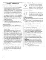
INSTALLATION REQUIREMENTS
.............................................
4
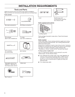
Tools and Parts
......................................................................
4
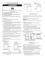
Location Requirements
.........................................................
5
Electrical Requirements
........................................................
6
Install Leveling Legs
..............................................................
7
Electrical Connection
............................................................
7
VENTING
...................................................................................
13
Venting Requirements
.........................................................
13
Plan Vent System
.................................................................
14
Venting Kits
..........................................................................
14
Install Vent System
..............................................................
16
Connect Vent
........................................................................
16
Level Dryer
...........................................................................
16
Complete Installation Checklist
.........................................
16
Reverse Door Swing (Optional)
..........................................
17
Troubleshooting
...................................................................
19
ELECTRIC DRYER INSTALLATION INSTRUCTIONS
29" WIDE MODELS - U.S.A. ONLY
Para obtener acceso al manual de uso y cuidado en español, o para obtener información adicional acerca de su producto, visite:
www.whirlpool.com
Tenga listo su número de modelo completo. Puede encontrar el número de modelo y de serie dentro de la cavidad superior de la puerta.
Table of Contents