Maytag MER7775WB Installation Instructions
Maytag MER7775WB Manual
 |
View all Maytag MER7775WB manuals
Add to My Manuals
Save this manual to your list of manuals |
Maytag MER7775WB manual content summary:
- Maytag MER7775WB | Installation Instructions - Page 1
INSTALLATION INSTRUCTIONS 30" (76 CM) FREESTANDING ELECTRIC RANGES Table of Contents RANGE SAFETY 2 INSTALLATION REQUIREMENTS 3 Tools and Parts 3 Location Requirements 3 Electrical Requirements - U.S.A. Only 4 INSTALLATION INSTRUCTIONS 6 Unpack Range 6 Install Anti-Tip Bracket 6 Electrical - Maytag MER7775WB | Installation Instructions - Page 2
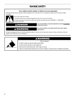
RANGE SAFETY Your safety and the safety of others are very important. We have provided many important safety messages in this manual and the range and be killed. Connect anti-tip bracket to rear range foot. Reconnect the anti-tip bracket, if the range is moved. Failure to follow these instructions - Maytag MER7775WB | Installation Instructions - Page 3
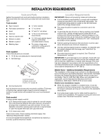
REQUIREMENTS Tools and Parts Gather the required tools and parts before starting installation. Read and follow the instructions provided with any tools listed here. Tools needed ■ Tape measure ■ ¼" drive ratchet ■ Flat-blade screwdriver ■ Level ■ Hammer ■ Hand or electric drill ■ Wrench or - Maytag MER7775WB | Installation Instructions - Page 4
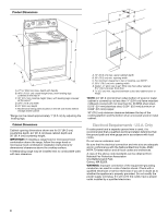
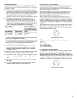
less than No. 28 MSG sheet steel, 0.015" (0.4 mm) stainless steel, 0.024" (0.6 mm) aluminum or 0.020" (0.5 mm) copper. 30" (76.2 cm) minimum clearance between the top of the cooking platform and the bottom of an uncovered wood or metal cabinet. Electrical Requirements - U.S.A. Only If codes permit - Maytag MER7775WB | Installation Instructions - Page 5
, you must determine the type of electrical connection you will be using and follow the instructions provided for it here. ■ Range must be connected to the proper electrical voltage and frequency as specified on the model/serial number rating plate. The model/serial number rating plate is located - Maytag MER7775WB | Installation Instructions - Page 6
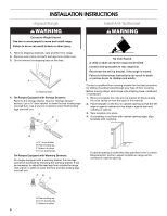
INSTALLATION INSTRUCTIONS Unpack Range WARNING Excessive Weight Hazard Use two or more people to move and install range. Failure to do so can result in back or other injury. 1. Remove shipping materials, tape and film from range. 2. Remove oven racks and parts package from inside oven. 3. Do not - Maytag MER7775WB | Installation Instructions - Page 7
grounded outlet. Failure to follow these instructions can result in death, fire, or electrical shock. Electrical Shock Hazard Disconnect power before servicing. Use 8 gauge copper or 6 gauge aluminum wire. Electrically ground range. Failure to follow these instructions can result in death, fire, or - Maytag MER7775WB | Installation Instructions - Page 8
volt minimum, 40-amp, range power supply cord 3-wire homes ■ Recreational vehicles ■ In an area where local codes prohibit grounding through the neutral 1. Part of metal ground strap must be cut out and removed. A B C 5. Complete installation following instructions for your type of electrical - Maytag MER7775WB | Installation Instructions - Page 9
UL listed strain relief D. Power supply cord wires 4. Use a Phillips screwdriver to connect the green ground wire from the power supply cord to the range with the ground-link screw and ground-link section. The ground wire must be attached first. 5. Use ³⁄₈" nut driver to connect the neutral (white - Maytag MER7775WB | Installation Instructions - Page 10
electrical supply (4-wire or 3-wire connection). 4-wire Connection: Direct Wire Use this method for: ■ New branch-circuit installations (1996 NEC) ■ Mobile homes ■ Recreational vehicles ■ In an area where local codes prohibit grounding through the neutral 1. Part wire to the range with the ground- - Maytag MER7775WB | Installation Instructions - Page 11
local codes permit connecting ground conductor to neutral supply wire. 1. Pull the wires through the conduit on cord/conduit plate on bottom of range. Allow enough slack to easily attach the wiring to the terminal block. A B C 2. Attach terminal lugs to line 2 (red), bare (green) ground, and line - Maytag MER7775WB | Installation Instructions - Page 12
back into position. Check that rear leveling leg is engaged in anti-tip bracket. NOTE: Range must be level for satisfactory baking performance. 4. Replace the storage drawer (on some models). A. Drawer clip 3. Depress the drawer clip by pressing the screwdriver handle toward the side of the storage - Maytag MER7775WB | Installation Instructions - Page 13
the Use and Care Guide for specific instruction on range operation. If range does not operate, check the following: ■ Household fuse is intact and tight; or circuit breaker has not tripped. ■ Range is plugged into an outlet. ■ Electrical supply is connected. ■ See "Troubleshooting" in the Use and - Maytag MER7775WB | Installation Instructions - Page 14
-tip bracket is installed: ■ Look for the anti-tip bracket securely attached to floor. ■ Slide range back so rear range foot is under anti-tip bracket. Electrical Shock Hazard Disconnect power before servicing. Replace all parts and panels before operating. Failure to do so can result in death or - Maytag MER7775WB | Installation Instructions - Page 15
Left edge ANTI-TIP BRACKET TEMPLATE Cut on dotted lines and place the left edge against the left side cabinet and the top edge against the rear wall. Top edge 15 - Maytag MER7775WB | Installation Instructions - Page 16
W10252706B © 2009. All rights reserved. 9/09 Printed in U.S.A.
-
 1
1 -
 2
2 -
 3
3 -
 4
4 -
 5
5 -
 6
6 -
 7
7 -
8
-
9
-
10
-
11
-
12
-
13
-
14
-
15
-
16
 |
 |

INSTALLATION INSTRUCTIONS
30" (76 CM) FREESTANDING ELECTRIC RANGES
Table of Contents
RANGE SAFETY
...................................................................................
2
INSTALLATION REQUIREMENTS
......................................................
3
Tools and Parts
..................................................................................
3
Location Requirements
......................................................................
3
Electrical Requirements - U.S.A. Only
...............................................
4
INSTALLATION INSTRUCTIONS
........................................................
6
Unpack Range
....................................................................................
6
Install Anti-Tip Bracket
.......................................................................
6
Electrical Connection - U.S.A. Only
...................................................
7
Verify Anti-Tip Bracket Location
......................................................
12
Level Range
......................................................................................
12
Storage Drawer
................................................................................
12
Complete Installation
.......................................................................
13
Moving the Range
............................................................................
14
ANTI-TIP BRACKET TEMPLATE
.....................................................
15
IMPORTANT:
Save for local electrical inspector's use.
W10252706B