Maytag MER8670AW Installation Guide
Maytag MER8670AW Manual
 |
View all Maytag MER8670AW manuals
Add to My Manuals
Save this manual to your list of manuals |
Maytag MER8670AW manual content summary:
- Maytag MER8670AW | Installation Guide - Page 1
INSTALLATION INSTRUCTIONS 30" (76 CM) FREESTANDING ELECTRIC RANGES Table of Contents RANGE SAFETY 2 INSTALLATION REQUIREMENTS 3 Tools and Parts 3 Location Requirements 3 Electrical Requirements - U.S.A. Only 5 INSTALLATION INSTRUCTIONS 6 Unpack Range 6 Install Anti-Tip Bracket 6 Electrical - Maytag MER8670AW | Installation Guide - Page 2
RANGE SAFETY Your safety and the safety of others are very important. We have provided many important safety messages in this manual anti-tip bracket if range is moved. Do not operate range without anti-tip bracket installed and engaged. Failure to follow these instructions can result in death - Maytag MER8670AW | Installation Guide - Page 3
for Manufactured Home Installations, ANSI A225.1/NFPA 501A or local codes. Mobile home installations require: ■ When this range is installed in a mobile home, it must be secured per the instructions in this document. ■ Four-wire power supply cord or cable must be used in a mobile home installation - Maytag MER8670AW | Installation Guide - Page 4
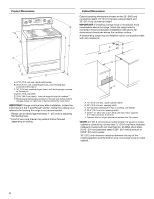
to front of cooktop** F. Model/serial rating plate (located on the left side frame behind storage drawer or right side of frame behind the oven door) IMPORTANT: Range must be level after installation. Follow the instructions in the "Level Range" section. Using the cooktop as a reference for leveling - Maytag MER8670AW | Installation Guide - Page 5
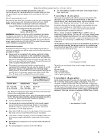
conductor can result in a risk of electric shock. Check with a qualified electrician or service technician if you are in doubt as 22 m) long. ■ Range must be connected to the proper electrical voltage and frequency as specified on the model/serial rating plate. The model/serial rating plate is - Maytag MER8670AW | Installation Guide - Page 6
Wrench or pliers D. Front leveling leg WARNING Tip Over Hazard A child or adult can tip the range and be killed. Install anti-tip bracket to floor or wall per installation instructions. Slide range back so rear range foot is engaged in the slot of the anti-tip bracket. Re-engage anti-tip bracket if - Maytag MER8670AW | Installation Guide - Page 7
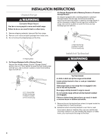
to the wall or floor with the two #12 x 1⁵⁄₈" screws provided. 6. Move range close enough to opening to allow for final electrical connections. Remove shipping base, cardboard or hardboard from under range. 7. Move range into its final location, making sure rear leveling leg slides into anti-tip - Maytag MER8670AW | Installation Guide - Page 8
grounded outlet. Failure to follow these instructions can result in death, fire, or electrical shock. Electrical Shock Hazard Disconnect power before servicing. Use 8 gauge copper or 6 gauge aluminum wire. Electrically ground range. Failure to follow these instructions can result in death, fire, or - Maytag MER8670AW | Installation Guide - Page 9
following instructions for your type of electrical connection: 4-wire (recommended) 3-wire (if 4-wire is not available) Electrical 2. Use a Phillips screwdriver to remove the ground-link screw from the back of the range. Save the ground-link screw and the end of the ground link under the screw - Maytag MER8670AW | Installation Guide - Page 10
6. Replace terminal block access cover. Direct Wire Installation: Copper or Aluminum Wire This range may be connected directly to the fuse disconnect or circuit breaker box. Depending on your electrical supply, make the required 3-wire or 4-wire connection. 1. Strip outer covering back 3" (7.6 cm - Maytag MER8670AW | Installation Guide - Page 11
Specifications chart. A B A B C A. Metal ground strap B. Discard C. Ground-link screw 2. Use a Phillips screwdriver to remove the ground-link screw from the back of the range. Save the ground-link screw and the end of the ground link under the screw. 3. Pull the wires through the strain relief on - Maytag MER8670AW | Installation Guide - Page 12
if local codes permit connecting ground conductor to neutral supply wire. 1. Pull the wires through the conduit on cord/conduit plate on bottom of range. Allow enough slack to easily attach the wiring to the terminal block. A 3. Use ³⁄₈" nut driver to connect the bare (green) ground wire to the - Maytag MER8670AW | Installation Guide - Page 13
without anti-tip bracket installed and engaged. Please reference the "Assistance or Service" section of the Use and Care Guide, or the cover or "Warranty" section of the User Instructions, to contact service. Level Range Determine if you have AquaLift™ Technology or Steam Clean by referring to the - Maytag MER8670AW | Installation Guide - Page 14
glides on both sides. Storage Drawer (on some models) The storage drawer can be removed. Before removing, placed in the drawer. Oven Door For normal range use, it is not suggested to remove the sure the oven is off and cool. Then, follow these instructions. The oven door is heavy. To Remove: 1. Open - Maytag MER8670AW | Installation Guide - Page 15
an "F9" or "F9, E0" error code, the electrical outlet in the home may be miswired. Contact a qualified electrician to verify the electrical supply. ■ See the "Troubleshooting" section in the Use and Care Guide or User Instructions. When the range has been on for 5 minutes, check for heat. If - Maytag MER8670AW | Installation Guide - Page 16
W10403811B © 2011. All rights reserved. TM AQUALIFT is a trademark of Whirlpool, U.S.A. 12/11 Printed in U.S.A.
-
 1
1 -
 2
2 -
 3
3 -
 4
4 -
 5
5 -
 6
6 -
 7
7 -
8
-
9
-
10
-
11
-
12
-
13
-
14
-
15
-
16
 |
 |

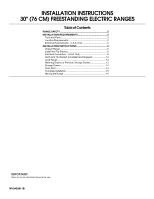
INSTALLATION INSTRUCTIONS
30" (76 CM) FREESTANDING ELECTRIC RANGES
Table of Contents
RANGE SAFETY
.............................................................................
2
INSTALLATION REQUIREMENTS
................................................
3
Tools and Parts
............................................................................
3
Location Requirements
................................................................
3
Electrical Requirements - U.S.A. Only
.........................................
5
INSTALLATION INSTRUCTIONS
..................................................
6
Unpack Range
.............................................................................
6
Install Anti-Tip Bracket
.................................................................
6
Electrical Connection - U.S.A. Only
.............................................
8
Verify Anti-Tip Bracket Is Installed and Engaged
......................
12
Level Range
...............................................................................
13
Warming Drawer or Premium Storage Drawer
..........................
13
Storage Drawer
..........................................................................
14
Oven Door
..................................................................................
14
Complete Installation
.................................................................
15
Moving the Range
......................................................................
15
IMPORTANT:
Save for local electrical inspector's use.
W10403811B