Maytag MGC4430BDB Installation Instructions
Maytag MGC4430BDB - 30 Inch Gas Cooktop Manual
 |
UPC - 883049141862
View all Maytag MGC4430BDB manuals
Add to My Manuals
Save this manual to your list of manuals |
Maytag MGC4430BDB manual content summary:
- Maytag MGC4430BDB | Installation Instructions - Page 1
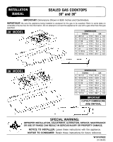
INSTALLATION MANUAL SEALED GAS COOKTOPS 30" and 36" IMPORTANT: Dimensions Shown in Both Inches and Centimeters. IMPORTANT: Be sure the appliance being installed is equipped for the gas to be supplied. Refer to serial plate on underside of burner box for this information. Do not attempt to convert - Maytag MGC4430BDB | Installation Instructions - Page 2
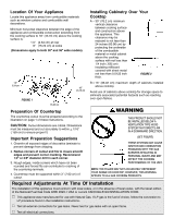
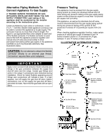
36″ wide models). Installing Cabinetry Over Your Cooktop A = 30 must be supported within 3″ PROBLEMS WITH THE GAS Gas. If LP gas is the fuel of choice, follow the conversion to LP procedure found in the installation instructions. V Test all external connections for gas leaks. Never test for gas - Maytag MGC4430BDB | Installation Instructions - Page 3
of the conversion adjustments described on pages 7 and 8 must be made by a qualified service technician before attempting to operate the cooktop on that gas. Natural gas should be supplied to the appliance pressure regulator at a line pressure between 6 and 14 inches of water column or, if converted - Maytag MGC4430BDB | Installation Instructions - Page 4
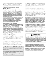
Connecting Appliance To Gas Supply A QUALIFIED SERVICE TECHNICIAN OR GAS APPLIANCE INSTALLER MUST MAKE THE GAS SUPPLY CONNECTION. Leak testing of the appliance shall be conducted by the installer according to the instructions given. Gas supply piping MUST conform to all local, municipal and state - Maytag MGC4430BDB | Installation Instructions - Page 5
Gas Supply A TRAINED SERVICE TECHNICIAN OR GAS APPLIANCE INSTALLER MUST MAKE THE GAS SUPPLY CONNECTION. Leak testing of the appliance shall be conducted by the installer according to the instructions and manual shut-off valve are joined solidly to other permanent hard piping (either gas supply or - Maytag MGC4430BDB | Installation Instructions - Page 6
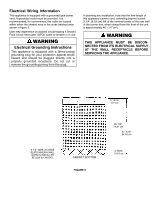
outlet or breaker is in use. WARNING Electrical Grounding Instructions This appliance is equipped with a (three-prong) AT THE WALL RECEPTACLE BEFORE SERVICING THE APPLIANCE. 3 13/16″ 9.7 cm 3 1/2″ (8.89 cm) WIDE SLATS WHEN A WALL OVEN IS INSTALLED BELOW 30″ MODEL CABINET BOTTOM FIGURE 5 29 - Maytag MGC4430BDB | Installation Instructions - Page 7
For Use With LP Gas WARNING Propane conversion is to be performed by a AUTHORIZED SERVICER (or other qualified agency) in accordance with the manufacturer's instructions and all codes and requirements of the authority having jurisdiction. Failure to follow instructions could result in serious - Maytag MGC4430BDB | Installation Instructions - Page 8
against figure 12. If the flames appear too large or too small, review each step to make sure it was completed correctly. FIGURE 10 C. LOW FLAME ADJUSTMENT (See figure 11) This appliance is shipped from the factory with low and high flame settings adjusted for use with natural gas - Maytag MGC4430BDB | Installation Instructions - Page 9
Natural Gas Orifice Spuds 5 BURNER MODEL (36″ WIDE) 1.55 1.42 1.42 1.42 1.61 FIGURE 13 4 BURNER MODEL (30 and follow the instructions in the appropriate illustration. C. RESET THE VALVES FOR NATURAL GAS 1. Light one pictured "low" setting on figure 12. Proper adjustment will produce a stable - Maytag MGC4430BDB | Installation Instructions - Page 10
air, obtain the services of a qualified service technician. Some yellow tipping on LP gas is normal. Specified input rates are as shown in figures 15 and 16 below. 5 BURNER MODEL (36″ Wide) 4 BURNER MODEL (30″ Wide) FIGURE 15 36″ Cooktop INPUT RATES - NATURAL GAS / LP GAS (BTU/HR) BURNER - Maytag MGC4430BDB | Installation Instructions - Page 11
follow installation instructions provided with the gas appliance connector and the warning label attached to the connector. Service-Parts Information When your cooktop requires service or replacement parts, contact your dealer or authorized service agency. Please give the complete model and serial - Maytag MGC4430BDB | Installation Instructions - Page 12
pulgadas y centímetros. IMPORTANTE: Asegúrese de que el electrodoméstico que se instalará esté equipado con el gas que se surtirá. Consulte la placa de datos que se encuentra en la parte inferior de la caja del quemador para obtener esa información. No trate de convertir este electrodoméstico para - Maytag MGC4430BDB | Installation Instructions - Page 13
con cuando menos 1/4 pulgadas (0,635 cm) de un aislante de FIGURA 2 partículas de madera con una hoja metálica de cuando menos 0,0122 pulgadas de CAUSAR PROBLEMAS DE IGNICIÓN Y DE COMBUSTIÓN CON LOS QUEMADORES A GAS RESULTANDO EN LESIONES PERSONALES Y PUEDEN AFECTAR LA MANERA DE COCINAR DE - Maytag MGC4430BDB | Installation Instructions - Page 14
La placa de datos se encuentra localizada en la parte inferior de la unidad. Si está aprobada, de gas tipo "T" manual en la tubería del suministro de gas. Cuando se utiliza un conector flexible de gas, la acción del gas LP. PRECAUCIÓN: La garantía queda anulada en el equipo Maytag que se instale de - Maytag MGC4430BDB | Installation Instructions - Page 15
) CAJA DEL QUEMADOR (PARTE POSTERIOR DEL ELECTRODOMÉSTICO) ENTRADA AL MÚLTIPLE (3/8″ N.P.T.) REGULADOR DE PRESIÓN DEL ELECTRODOMÉSTICO TODAS LAS UNIONES DE TUBERÍA LATERAL DE SUMINISTRO 1/2″ N.P.T. VÁLVULA MANUAL DE CIERRE CODO FIGURA 3 HACIA LA ENTRADA DE GAS ADVERTENCIA Puede ocurrir un - Maytag MGC4430BDB | Installation Instructions - Page 16
conector flexible asegúrese de que tanto el regulador de presión como la válvula de cierre manual están firmemente unidas a otra tubería rígida permanente (ya sea el suministro de gas o el múltiple del electrodoméstico) para que esté fijo físicamente. Vea las ilustraciones a continuación. PRECAUCI - Maytag MGC4430BDB | Installation Instructions - Page 17
cm 37 3/16″ 94,46 cm TABLILLA DE 3 1/2″ (8,89 cm) DE ANCHO CUANDO SE INSTALA UN HORNO DE PARED DEBAJO DE UN MODELO DE 30″ PARTE INFERIOR DEL GABINETE FIGURA 5 4″ MÁX. 10,16 cm - Maytag MGC4430BDB | Installation Instructions - Page 18
debe estar cerrada antes de realizar la conversión. Este electrodoméstico está ajustado de fábrica para usarse con gas natural. Para convertirlo a gas LP (propano o butano), deben realizarse cada una de las siguientes modificaciones: (A, B y C) A. REEMPLACE TODAS LAS COPAS DE ORIFICIO Paso 1: Quite - Maytag MGC4430BDB | Installation Instructions - Page 19
de llama alta y baja listos para usarse con gas natural. Si desea ajustarlos para usarse con gas LP siga las instrucciones a continuación: 1. Quite la llama de cada quemador en los ajustes HI y LO contra los de la figura 12. Si las llamas parecen estar demasiado grandes o pequeñas, revise cada paso - Maytag MGC4430BDB | Installation Instructions - Page 20
según se muestra en las figuras 13 y 14. Instalación de las copas de orificio de gas natural MODELO DE 5 QUEMADORES (DE 36″ DE ANCHO) 1,55 1,42 1,42 1,42 1,61 el ajuste Hi y Lo contra la figura 12. Si las llamas parecen estar demasiado grandes o pequeñas, asegúrese de que - Maytag MGC4430BDB | Installation Instructions - Page 21
otra parte parece no tener suficiente aire, consiga los servicios de un técnico calificado. Algunas puntas amarillas del gas LP FIGURA 15 36″ Modelo CLASIFICACIÓN DE ENTRADA - GAS NATURAL / GAS LP (BTU/HR) UBICACIÓN DEL QUEMADOR Hi Lo Delantero derecho 12 500 / 10 500 1 300 / 1 300 - Maytag MGC4430BDB | Installation Instructions - Page 22
asegurarla al mostrador. Pueden añadirse soportes de sujeción al frente y en la parte posterior. Comuníquese con el proveedor o con la agencia autorizada de servicio. de instalación provistas con el conector del electrodoméstico de gas y la etiqueta de advertencia sujeta al conector. Información - Maytag MGC4430BDB | Installation Instructions - Page 23
INTÉGRÉS MISE EN SERVICE 36 po et 30 0,2 E 29 1/2 + 1/16 74,9 + 0,2 F 21 + 1/16 53,3 + 0,2 G 3 13/16 + 1/16 9,7 + 0,2 H 12 1/4 + 1/16 31,1 + 0,2 MODÈLE DE 36 PO (91,4 cm) DIMENSIONS pouces cm A 34 1/2 + 1/16 87,6 + 0,2 B instructions avec l'appareil. À L'INTENTION DU CONSOMMATEUR : - Maytag MGC4430BDB | Installation Instructions - Page 24
doit avoir un support à une distance maximum Gas Code américain ou du CODE DES INSTALLATIONS B149 CAN/ACG en vigueur. V Cet appareil est conçu pour fonctionner au gaz naturel. S'il doit être utilisé avec du GPL, suivre la méthode de conversion au GPL qui se trouve dans les instructions de mise en service - Maytag MGC4430BDB | Installation Instructions - Page 25
dernière édition, du National Fuel Gas Code aux États--Unis ou avec le code de mise en service CAN/ACG- B149 en vigueur. Une fois les raccords. ATTENTION : La garantie est nulle si les consignes de Maytag concernant la pose du matériel ne sont pas respectées. L'appareil instructions en conséquence. - Maytag MGC4430BDB | Installation Instructions - Page 26
les joints et raccords de l'appareil si ceux--ci ont pu se trouver desserrés pendant la mise en service. Vérifier les fuites ! Si des bulles apparaissent autour des joints et des raccords, il y a une (homologation UL). Installer et utiliser le d tecteur conform ment aux instructions du fabricant. - Maytag MGC4430BDB | Installation Instructions - Page 27
la conduite de gaz et l'appareil. Inclure les joints et raccords de l'appareil si ceux--ci ont pu se trouver desserrés pendant la mise en service. Vérifier les fuites ! Si des bulles apparaissent autour des joints et des raccords, il y a une fuite. En cas de fuite, fermer le robinet d'alimentation - Maytag MGC4430BDB | Installation Instructions - Page 28
, vue de l'avant de l'appareil, est d'environ 46 po (117 cm). AVERTISSEMENT CETTE APPAREIL DOIT ÊTRE DÉBRANCHÉ DE LA PRISE MURALE AVANT TOUTE INTERVENTION DE SERVICE APRÈSVENTE. 3 13/16″ 9,7 cm LATTES DE 3 1/2 PO (8,9 cm) DE LARGE LORSQU'UN FOUR ENCASTRÉ EST MONTÉ SOUS LE MODÈLE DE 30 PO (76 - Maytag MGC4430BDB | Installation Instructions - Page 29
de toutes autorités compétentes. La non--observation des consignes pourrait entraîner des blessures graves ou des dégâts. Le prestataire de service qualifié qui effectue la conversion en assume l'entière responsabilité. AVERTISSEMENT Fermer le gaz et l'électricité avant de procéder à la conversion - Maytag MGC4430BDB | Installation Instructions - Page 30
et C de la conversion terminées, vérifier l'apparence de la flamme de chaque brûleur à feu doux et à plein feu (Hi) par rapport à la figure 12. Si la flamme paraît trop grande ou trop petite, revoir chaque étape pour s'assurer qu'elle a été effectuée correctement. APPARENCE DE LA FLAMME À PLEIN FEU - Maytag MGC4430BDB | Installation Instructions - Page 31
4 et 5). Identifier le type de détendeur de l'appareil et suivre les instructions de l'illustration qui convient. C. RÉGLER LES BOUTONS DE COMMANDE AU GAZ la flamme illustrée pour le réglage « feu doux » de la figure 12. Une flamme correctement réglée est stable, bleue et d'une longueur minimum. - Maytag MGC4430BDB | Installation Instructions - Page 32
apport d'air insuffisant, faire appel à un technicien de service après--vente qualifié. Il est normal que la flamme pr /GPL (BTU/H) EMPLACEMENT DU BRÛLEUR Avant droit Arrière droit Avant gauche Arrière gauche Centre Hi (plein feu) 12 500 / 10 500 9 200 / 9 100 9 200 / 9 100 10 500 / 9 100 9 200 / - Maytag MGC4430BDB | Installation Instructions - Page 33
rebord de chaque côté. Visser les longues vis de fixation fournies dans les supports de fixation. Serrer les vis de façon à maintenir fermement l'appareil technicien de service après--vente qualifié. La personne effectuant le dépannage DOIT suivre les instructions de mise en service fournies avec
-
 1
1 -
 2
2 -
 3
3 -
 4
4 -
 5
5 -
 6
6 -
 7
7 -
8
-
9
-
10
-
11
-
12
-
13
-
14
-
15
-
16
-
17
-
18
-
19
-
20
-
21
-
22
-
23
-
24
-
25
-
26
-
27
-
28
-
29
-
30
-
31
-
32
-
33
 |
 |
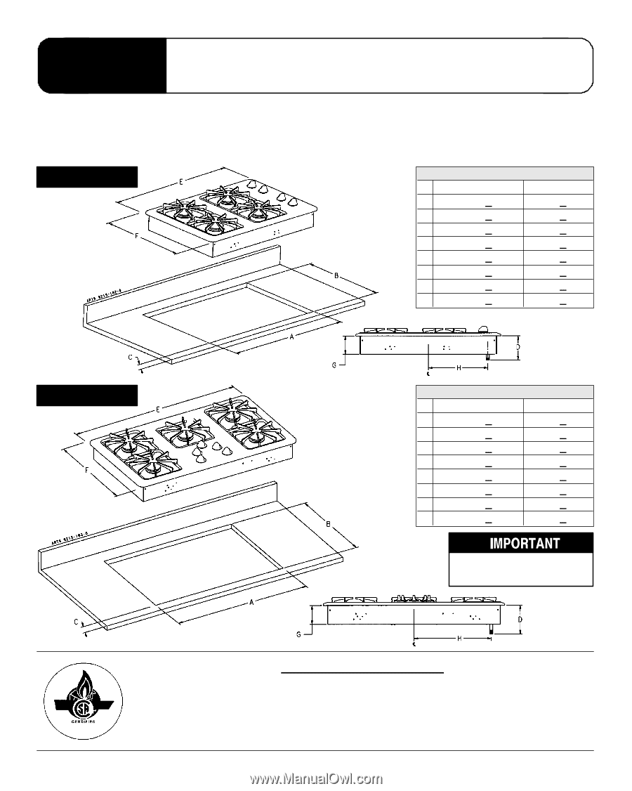
IMPORTANT:
Dimensions Shown in Both Inches and Centimeters.
IMPORTANT:
Be sure the appliance being installed is equipped for the gas to be supplied. Refer to serial plate on
underside of burner box for this information. Do not attempt to convert this appliance for use with a gas other than the type
specified.
W10187822
(01-08-00)
CUTOUT DIMENSIONS
ARE CRITICAL
30
″
MODEL
INSTALLATION
MANUAL
SEALED GAS COOKTOPS
30” and 36”
SPECIAL W
ARNING:
IMPROPER INSTALLATION, ADJUSTMENT, ALTERATION, SERVICE, MAINTENANCE
OR USE OF RANGE CAN RESULT IN SERIOUS INJURY OR PROPERTY DAMAGE.
NOTICE TO INSTALLER:
Leave these instructions with the appliance.
NOTICE TO CONSUMER:
Retain these instructions for future reference.
DIMENSIONS
inches
cm
A
28 1/2
+
1/16
72.4
+
0.2
B
19 15/16 +
1/16
50.6
+
0.2
C
2 1/8
+
1/16
5.4
+
0.2
D
5 1/4
+
1/16
13.3
+
0.2
E
29 1/2
+
1/16
74.9
+
0.2
F
21
+
1/16
53.3
+
0.2
G
3 13/16
+
1/16
9.7
+
0.2
H
12 1/4
+
1/16
31.1
+
0.2
36
″
MODEL
DIMENSIONS
inches
cm
A
34 1/2
+
1/16
87.6
+
0.2
B
19 15/16 +
1/16
50.6
+
0.2
C
2 1/8
+
1/16
5.4
+
0.2
D
5 1/4
+
1/16
13.3
+
0.2
E
36
+
1/16
91.4
+
0.2
F
21
+
1/16
53.3
+
0.2
G
3 13/16
+
1/16
9.7
+
0.2
H
15 1/4
+
1/16
38.7
+
0.2
Reviewed by Stewart, Steven | Released