Maytag MGR6600FZ Installation Guide
Maytag MGR6600FZ Manual
 |
View all Maytag MGR6600FZ manuals
Add to My Manuals
Save this manual to your list of manuals |
Maytag MGR6600FZ manual content summary:
- Maytag MGR6600FZ | Installation Guide - Page 1
Installation 13 GAS CONVERSIONS 14 LP Gas Conversion 14 Natural Gas Conversion 17 SÉCURITÉ DE LA CUISINIÈRE 20 EXIGENCES D'INSTALLATION 21 Outillage et pièces 21 Exigences d'emplacement 22 Spécifications électriques 23 Spécifications de l'alimentation en gaz 24 INSTRUCTIONS D'INSTALLATION - Maytag MGR6600FZ | Installation Guide - Page 2
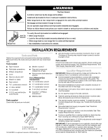
from a neighbor's phone. Follow the gas supplier's instructions. • If you cannot reach your gas supplier, call the fire department. - Installation and service must be performed by a qualified installer, service agency or the gas supplier. WARNING: Gas leaks cannot always be detected by smell - Maytag MGR6600FZ | Installation Guide - Page 3
floor or wall. • Slide range back so rear range foot is under anti-tip bracket. • See installation instructions for details. INSTALLATION REQUIREMENTS Tools and Parts Gather the required tools and parts before starting installation. Read and follow the instructions provided with any tools listed - Maytag MGR6600FZ | Installation Guide - Page 4
range to front of cooktop** F. Model/serial rating plate (located on the oven frame behind the top left side of the oven door) IMPORTANT: Range must be level after installation. Follow the instructions in the "Level Range shaded areas are recommended for installation of rigid gas pipe. G. 4¹⁄₂" (11.4 - Maytag MGR6600FZ | Installation Guide - Page 5
/CGA B149 - latest edition. IMPORTANT: Leak testing of the range must be conducted according to the manufacturer's instructions. Type of Gas Natural gas: This range is factory set for use with Natural gas. See "Gas Conversions" section. The model/serial rating plate located on the oven frame behind - Maytag MGR6600FZ | Installation Guide - Page 6
½ psi (3.5 kPa). Line pressure testing at ½ psi gauge (14" WCP) or lower The range must be isolated from the gas supply piping system by closing its individual manual shutoff valve during any pressure testing of the gas supply piping system at test pressures equal to or less than ½ psi (3.5 kPa). 6 - Maytag MGR6600FZ | Installation Guide - Page 7
INSTALLATION INSTRUCTIONS Unpack Range Install Anti-Tip Bracket WARNING Excessive Weight Hazard Use two or more people to move and install range. Failure to do so can result in back or other injury. WARNING 1. Remove shipping materials, tape and film from range. 2. Remove oven racks and parts - Maytag MGR6600FZ | Installation Guide - Page 8
base, cardboard or hardboard to continue installing the range using the following installation instructions. Explosion Hazard Use a new CSA International approved gas supply line. Install a shut-off valve. Securely tighten all gas connections. If connected to LP, have a qualified person make sure - Maytag MGR6600FZ | Installation Guide - Page 9
manual shutoff valve in the gas supply line. The valve is open when the handle is parallel to the gas pipe. A B WARNING Electrical Shock Hazard Plug into a grounded 3 prong outlet. Do not remove ground prong. Do not use an adapter. Do not use an extension cord. Failure to follow these instructions - Maytag MGR6600FZ | Installation Guide - Page 10
installed correctly. Do not operate the range without anti-tip bracket installed and engaged. Please reference the "Assistance or Service" section of the Use and Care Guide, or the cover or "Warranty" section of the User Instructions, to contact service. Level Range ignites the gas. Check Operation - Maytag MGR6600FZ | Installation Guide - Page 11
and Care Guide or User Instructions for proper operation of the oven controls. Adjust Oven Bake Burner Flame (if needed) 1. On models with a needs to be adjusted, locate the air shutter near the center rear of the range. Loosen the locking screw and rotate the air shutter until the proper flame - Maytag MGR6600FZ | Installation Guide - Page 12
B. Air shutter 4. Press CANCEL/OFF when finished. Warming Drawer or Premium Storage Drawer (on some models) Remove all items from inside the warming drawer or premium storage drawer, and allow the range to cool completely before attempting to remove the drawer. To Remove: 1. Open the warming drawer - Maytag MGR6600FZ | Installation Guide - Page 13
grounded 3 prong outlet. ■ Electrical supply is connected. ■ See "Troubleshooting" in the Use and Care Guide or User Instructions. 8. When the range has been on for 5 minutes, check for heat. If the range is cold, turn off the range and check that the gas supply line shutoff valve is open. ■ If the - Maytag MGR6600FZ | Installation Guide - Page 14
personnel, authorized gas company personnel, and authorized service personnel. Failure to do so can result in death, explosion, or fire. Tip Over Hazard A child or adult can tip the range and be killed. Install anti-tip bracket to floor or wall per installation instructions. Slide range back so - Maytag MGR6600FZ | Installation Guide - Page 15
correct LP gas orifice spud placement. LP Gas Orifice Spud Chart for Surface Burners Burner Rating Color Size ID Number 14,000 BTU 11,000 BTU 8,000 BTU 5,000 BTU Yellow/Orange Yellow/Brown Yellow/Black Yellow/White 1.07 mm 0.99 mm 0.85 mm 0.70 mm L107 L99 L85 L70 NOTE: Refer to the Model - Maytag MGR6600FZ | Installation Guide - Page 16
broil burner orifice hood counterclockwise to remove. The hood will be stamped with a "53." 4. Replace the "53" hood with a "090" hood. Install the LP gas broiler burner orifice hood, turning it clockwise until snug. IMPORTANT: Do not overtighten. A x.xx A. Orifice spud 9. Position the back of the - Maytag MGR6600FZ | Installation Guide - Page 17
to "Complete Installation" in the "Installation Instructions" section of this manual to complete this procedure. NOTE: Be sure to save the orifices that have just been replaced in the conversion. Natural Gas Conversion WARNING To Convert Gas Pressure Regulator (LP Gas to Natural Gas) 1. Remove - Maytag MGR6600FZ | Installation Guide - Page 18
N180 N155 N140 N110 NOTE: Refer to the Model Number and Serial Number Plate located on the oven frame behind the top left side of the oven door for proper sizing of spuds for each burner location. 5. Place LP gas orifice spuds in plastic parts bag for future use and keep with package containing - Maytag MGR6600FZ | Installation Guide - Page 19
is very important. Natural gas flames do not have yellow tips. 3. Refer to "Complete Installation" in the "Installation Instructions" section of this manual to complete this procedure. NOTE: Be sure to save the orifices that have just been replaced in the conversion. C A. Broil burner B. Screws - Maytag MGR6600FZ | Installation Guide - Page 20
de gaz à partir du téléphone d'un voisin. Suivre ses instructions. • À défaut de joindre votre fournisseur de gaz, appeler les pompiers. - L'installation et l'entretien doivent être effectués par un installateur qualifié, une agence de service ou le fournisseur de gaz. AVERTISSEMENT : L'odorat ne - Maytag MGR6600FZ | Installation Guide - Page 21
la bride antibasculement au plancher ou au mur, conformément aux instructions d'installation. Faire glisser de nouveau la cuisinière de façon à ce de ■ Niveau détection des fuites ■ Perceuse manuelle ou Pour la conversion pour électrique l'alimentation au gaz propane/ ■ Clé ou pince gaz - Maytag MGR6600FZ | Installation Guide - Page 22
Part 280). Lorsque cette norme n'est pas applicable, l'installation doit satisfaire aux critères de la norme Standard for Manufactured Home Installations ) IMPORTANT : La cuisinière doit être d'aplomb après l'installation. Suivre les instructions de la section "Réglage de l'aplomb de la cuisinière". - Maytag MGR6600FZ | Installation Guide - Page 23
24" (61,0 cm) de profondeur et 36" (91,4 cm) de hauteur. IMPORTANT : En cas d'installation d'une hotte ou d'un ensemble hotte/micro-ondes au-dessus de la cuisinière, suivre les instructions d'installation fournies avec la hotte ou l'ensemble hotte/micro-ondes concernant les dimensions de dégagement - Maytag MGR6600FZ | Installation Guide - Page 24
instructions peut causer un décès, une explosion ou un incendie. Observer toutes les prescriptions des codes et règlements en vigueur. IMPORTANT : L'installation é, consulter le fournisseur de gaz local. Conversion pour l'alimentation au propane : L'opération de conversion doit être exécutée par un - Maytag MGR6600FZ | Installation Guide - Page 25
ou inférieure à ½ lb/po² (3,5 kPa), on doit isoler la cuisinière de la canalisation de gaz par fermeture de son robinet d'arrêt manuel individuel. INSTRUCTIONS D'INSTALLATION Déballage de la cuisinière AVERTISSEMENT AD Risque du poids excessif Utiliser deux ou plus de personnes pour déplacer et - Maytag MGR6600FZ | Installation Guide - Page 26
personne adulte peut faire basculer la cuisinière, ce qui peut causer un décès. Fixer la bride antibasculement au plancher ou au mur, conformément aux instructions d'installation. Faire glisser de nouveau la cuisinière de façon à ce que le pied arrière de la cuisinière se trouve dans la fente - Maytag MGR6600FZ | Installation Guide - Page 27
d'adaptation. Veiller à ne pas déformer/écraser le raccord flexible. A Installer un robinet d'arrêt. Bien serrer chaque organe de connexion de la canalisation et le personnel d'entretien autorisé. Le non-respect de ces instructions peut causer un décès, une explosion ou un incendie. A. Détendeur - Maytag MGR6600FZ | Installation Guide - Page 28
fonctionner la cuisinière si la bride antibasculement n'est pas installée et engagée. Consulter la section "Assistance ou Service" du guide d'utilisation et d'entretien, la couverture ou la section "Garantie" des instructions d'utilisation pour obtenir les coordonnées des personnes à contacter. 28 - Maytag MGR6600FZ | Installation Guide - Page 29
ère n'est pas d'aplomb, la tirer vers l'avant jusqu'à ce que le pied de nivellement arrière se dégage de la bride antibasculement. 4. Suivre les instructions fournies pour le type 1 ou 2, en fonction du type de tiroir fourni avec la cuisinière. Style 1 : Sur les cuisinières équipées d'un tiroir - Maytag MGR6600FZ | Installation Guide - Page 30
de la tige de commande; ajuster les flammes à la taille désirée. 3. Réinstaller le bouton de commande. 4. Tester le fonctionnement du brûleur : faire passer du four et du gril. Consulter le Guide d'utilisation et d'entretien ou les instructions d'utilisation pour le bon fonctionnement des commandes - Maytag MGR6600FZ | Installation Guide - Page 31
après 50 à 60 secondes. Consulter le Guide d'utilisation et d'entretien ou les instructions d'utilisation pour le bon fonctionnement des commandes du tiroir de remisage de qualité supérieure pour le retirer complètement. Réinstallation : 1. Aligner les encoches de l'avant du tiroir avec les encoches - Maytag MGR6600FZ | Installation Guide - Page 32
, s'assurer que le four est éteint et froid. Puis, suivre ces instructions. La porte du four est lourde. Dépose : 1. Ouvrir la porte de la butée du tiroir 2. Soulever l'avant du tiroir et retirer ce dernier. Réinstallation : 1. Soulever l'avant du tiroir et placer l'arrière du tiroir dans la cuisini - Maytag MGR6600FZ | Installation Guide - Page 33
1. Vérifier que toutes les pièces sont maintenant installées. S'il reste une pièce inutilisée, passer en revue d'assistance ou de service : Veuillez consulter la section "Assistance ou service" dans le Guide d'utilisation et d'entretien ou la page de couverture des instructions d'utilisation, ou - Maytag MGR6600FZ | Installation Guide - Page 34
Fixer la bride antibasculement au plancher ou au mur, conformément aux instructions d'installation. Faire glisser de nouveau la cuisinière de façon à ce que Débrancher la cuisinière ou déconnecter la source de courant électrique. Conversion du détendeur de gaz (de gaz naturel à gaz propane ) 1. - Maytag MGR6600FZ | Installation Guide - Page 35
"LP" soit orientée de la manière indiquée à l'illustration ci-dessus. 6. Réinstaller le couvercle de plastique par-dessus le capuchon du détendeur. Conversion soulever pour enlever le gicleur. Conserver à part le gicleur du brûleur. C A D B A. Gicleur B. Support du gicleur C. Vis D. Électrode - Maytag MGR6600FZ | Installation Guide - Page 36
thermique Couleur Taille Code d'identification 14 000 BTU 11 000 BTU 8 000 BTU 5 000 BTU Jaune/Orange Jaune/Marron Jaune/Noir Jaune/Blanc installer la base du brûleur - utiliser les deux vis. 7. Réinstaller le chapeau de brûleur. 8. Répéter les étapes 1 à 7 pour les autres brûleurs. Conversion - Maytag MGR6600FZ | Installation Guide - Page 37
Conversion du brûleur de cuisson au gril (de gaz naturel à gaz propane) 1. alimenté au propane comportent une pointe légèrement jaune. 3. Voir le paragraphe "Achever l'installation" de la section "Instructions d'installation" du présent manuel pour achever cette procédure. REMARQUE : S'assurer de - Maytag MGR6600FZ | Installation Guide - Page 38
au plancher ou au mur, conformément aux instructions d'installation. Faire glisser de nouveau la cuisinière de ou déconnecter la source de courant électrique. Conversion du détendeur de gaz (de gaz propane à situé sous le capuchon. Vue de côté - avant A LP LP B D E NG NG C Vue de côté - apr - Maytag MGR6600FZ | Installation Guide - Page 39
Conserver à part le gicleur du brûleur. C A D B Conversion du br A B A. Gicleur B. Support du gicleur C. Vis D. BTU 17 000 BTU 15 000/15 500 BTU 14 200 BTU 13 000/13 500 BTU 12 000/12 500 BTU 9 500 BTU 8 000 BTU 5 000 BTU 6. Réinstaller la base du brûleur à l'aide des deux vis. 7. Réinstaller le - Maytag MGR6600FZ | Installation Guide - Page 40
" de la section "Instructions d'installation" du présent manuel pour achever cette procédure. REMARQUE : S'assurer de bien conserver les gicleurs qui ont été remplacés au cours de la conversion. ®/™ ©2015 Whirlpool. Used under license in Canada. All rights reserved. W10545337B Utilisée sous
-
 1
1 -
 2
2 -
 3
3 -
 4
4 -
 5
5 -
 6
6 -
 7
7 -
8
-
9
-
10
-
11
-
12
-
13
-
14
-
15
-
16
-
17
-
18
-
19
-
20
-
21
-
22
-
23
-
24
-
25
-
26
-
27
-
28
-
29
-
30
-
31
-
32
-
33
-
34
-
35
-
36
-
37
-
38
-
39
-
40
 |
 |
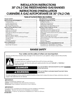
INSTALLATION INSTRUCTIONS
30" (76.2 CM) FREESTANDING GAS RANGES
INSTRUCTIONS D'INSTALLATION
CUISINIÈRE À GAZ AUTOPORTANTE DE 30" (76,2 CM)
RANGE SAFETY
W10545337B
Table of Contents/Table des matières
RANGE SAFETY
.............................................................................
1
INSTALLATION REQUIREMENTS
................................................
3
Tools and Parts
............................................................................
3
Location Requirements
................................................................
3
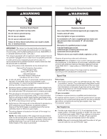
Electrical Requirements
...............................................................
5
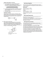
Gas Supply Requirements
...........................................................
5
INSTALLATION INSTRUCTIONS
..................................................
7
Unpack Range
..............................................................................
7
Install Anti-Tip Bracket
.................................................................
7
Make Gas Connection
.................................................................
8
Verify Anti-Tip Bracket Is Installed and Engaged
........................
9
Level Range
................................................................................
10
Electronic Ignition System
.........................................................
10
Warming Drawer or Premium Storage Drawer
..........................
12
Storage Drawer
..........................................................................
12
Oven Door
..................................................................................
13
Complete Installation
.................................................................
13
GAS CONVERSIONS
....................................................................
14
LP Gas Conversion
....................................................................
14
Natural Gas Conversion
.............................................................
17
SÉCURITÉ DE LA CUISINIÈRE
...................................................
20
EXIGENCES D’INSTALLATION
...................................................
21
Outillage et pièces
......................................................................
21
Exigences d'emplacement
.........................................................
22
Spécifications électriques
..........................................................
23
Spécifications de l’alimentation en gaz
.....................................
24
INSTRUCTIONS D'INSTALLATION
.............................................
25
Déballage de la cuisinière
..........................................................
25
Installation de la bride antibasculement
....................................
26
Raccordement à la canalisation de gaz
.....................................
27
Vérifier que la bride antibasculement est bien installée
et engagée
..................................................................................
28
Réglage de l'aplomb de la cuisinière
.........................................
29
Système d'allumage électronique
..............................................
29
Tiroir-réchaud ou tiroir de remisage de qualité supérieure
.......
31
Tiroir de remisage
.......................................................................
32
Porte du four
...............................................................................
32
Achever l’installation
..................................................................
33
CONVERSIONS POUR CHANGEMENT DE GAZ
.......................
34
Conversion pour l'alimentation au propane
...............................
34
Conversion pour l'alimentation au gaz naturel
..........................
38
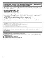
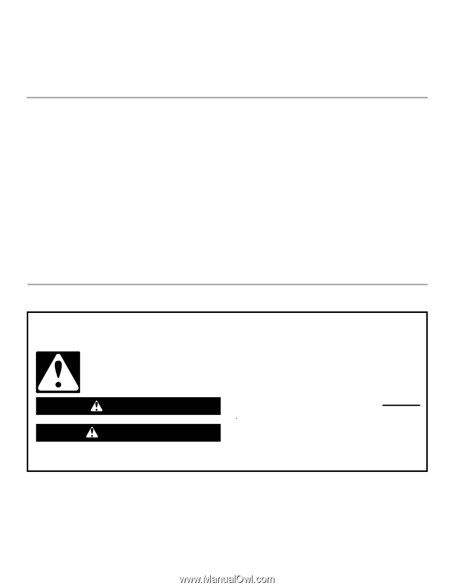
You can be killed or seriously injured if you don't immediately
You
can be killed or seriously injured if you don't follow
All safety messages will tell you what the potential hazard is, tell you how to reduce the chance of injury, and tell you what can
happen if the instructions are not followed.
Your safety and the safety of others are very important.
We have provided many important safety messages in this manual and on your appliance. Always read and obey all safety
messages.
This is the safety alert symbol.
This symbol alerts you to potential hazards that can kill or hurt you and others.
All safety messages will follow the safety alert symbol and either the word “DANGER” or “WARNING.”
These words mean:
follow instructions.
instructions.
DANGER
WARNING
IMPORTANT:
Save for local electrical inspector's use.
Installer:
Leave installation instructions with the homeowner.
Homeowner:
Keep installation instructions for future reference.
IMPORTANT :
À conserver pour consultation par l'inspecteur local des installations électriques.
Installateur :
Remettre les instructions d'installation au propriétaire.
Propriétaire :
Conserver les instructions d'installation pour référence ultérieure.