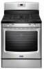
Maytag MGR8650ES Installation Guide
Maytag MGR8650ES Manual
 |
View all Maytag MGR8650ES manuals
Add to My Manuals
Save this manual to your list of manuals |
Maytag MGR8650ES manual content summary:
- Maytag MGR8650ES | Installation Guide - Page 1
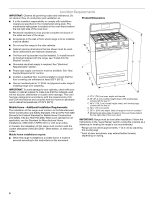
LA CUISINIÈRE 20 INSTALLATION REQUIREMENTS 3 Tools and Parts 3 Location Requirements 4 Electrical Requirements 5 Gas Supply Requirements 6 INSTALLATION INSTRUCTIONS 7 Unpack Range 7 Install Anti-Tip Bracket 8 Make Gas Connection 8 Verify Anti-Tip Bracket Is Installed and Engaged 10 Level - Maytag MGR8650ES | Installation Guide - Page 2
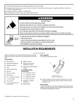
tell you what can happen if the instructions are not followed. WARNING: If the information in this manual is not followed exactly, a fire or instructions. • If you cannot reach your gas supplier, call the fire department. - Installation and service must be performed by a qualified installer, service - Maytag MGR8650ES | Installation Guide - Page 3
foot is engaged in the slot of the anti-tip bracket. Re-engage anti-tip bracket if range is moved. Do not operate range without anti-tip bracket installed and engaged. Failure to follow these instructions can result in death or serious burns to children and adults. Anti-Tip Bracket To verify the - Maytag MGR8650ES | Installation Guide - Page 4
E. 25 64.6 cm) depth. Back of range to front of cooktop** F. Model/serial rating plate (located on the oven frame behind the top right side of the oven door) IMPORTANT: Range must be level after installation. Follow the instructions in the "Level Range" section. Using the cooktop as a reference - Maytag MGR8650ES | Installation Guide - Page 5
not remove ground prong. Do not use an adapter. Do not use an extension cord. Failure to follow these instructions can result in death, fire, or electrical shock. IMPORTANT: The range must be electrically grounded in accordance with local codes and ordinances, or in the absence of local codes, with - Maytag MGR8650ES | Installation Guide - Page 6
and authorized service personnel. instructions. Type of Gas Natural gas: This range is design-certified by CSA International for use with Natural gas or, after proper conversion, for use with LP gas. ■ This range is factory set for use with Natural gas. See "Gas Conversions" section. The model - Maytag MGR8650ES | Installation Guide - Page 7
shown on the model/serial rating plate. Line pressure testing above ½ psi gauge (14" WCP) The range and its individual manual shutoff valve during any pressure testing of the gas supply piping system at test pressures equal to or less than ½ psi (3.5 kPa). INSTALLATION INSTRUCTIONS Unpack Range - Maytag MGR8650ES | Installation Guide - Page 8
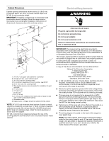
tip the range and be killed. Install anti-tip bracket to floor or wall per installation instructions. Slide range back so rear range foot is engaged : licensed heating personnel, authorized gas company personnel, and authorized service personnel. Failure to do so can result in death, explosion - Maytag MGR8650ES | Installation Guide - Page 9
A. Gas pressure regulator shutoff valve shown in the "on" position 2. Open the manual shutoff valve in the gas supply line. The valve is open when the handle to follow these instructions can result in death, fire, or electrical shock. 5. Plug into a grounded 3 prong outlet. 6. Slide range into final - Maytag MGR8650ES | Installation Guide - Page 10
without anti-tip bracket installed and engaged. Please reference the "Assistance or Service" section of the Use and Care Guide, or the cover or "Warranty" section of the User Instructions, to contact service. Level Range Determine if you have AquaLift® Technology or Steam Clean by referring to the - Maytag MGR8650ES | Installation Guide - Page 11
■ Check that the range is plugged in. Check contact your dealer or authorized service company for assistance. Check the control knob. If the "low" flame needs to be adjusted: Guide or User Instructions for proper operation of the oven controls. Adjust Oven Bake Burner Flame (if needed) 1. On models - Maytag MGR8650ES | Installation Guide - Page 12
Drawer (on some models) Remove all items from inside the warming drawer or premium storage drawer, and allow the range to cool completely before 50 to 60 seconds to light. Refer to the Use and Care Guide or User Instructions for proper operation of the oven controls. Adjust Oven Broil Burner Flame - Maytag MGR8650ES | Installation Guide - Page 13
models) Troubleshooting" in the Use and Care Guide or User Instructions. 8. When the range has been on for 5 minutes, check for heat. If the range is cold, turn off the range Service: Please reference the "Assistance or Service" section of the Use and Care Guide or the cover of the User Instructions - Maytag MGR8650ES | Installation Guide - Page 14
instructions can result in death or serious burns to children and adults. 1. Turn the manual shutoff valve to the closed position. B A C A. To range B. Manual shutoff valve "closed" position C. Gas supply line 2. Unplug range warming drawer compartment. NOTE: On models with a warming drawer, an - Maytag MGR8650ES | Installation Guide - Page 15
screwdriver, remove the burner base. NOTE: Reinstall one of the screws through the range cooktop to hold the orifice spud holder in place while removing and replacing the 85 mm 0.70 mm L107 L99 L85 L70 NOTE: Refer to the Model Number and Serial Number Plate located on the oven frame behind the top - Maytag MGR8650ES | Installation Guide - Page 16
To Convert Oven Bake Burner (Natural Gas to LP Gas) 1. Remove the oven racks. 2. Remove 2 screws at the rear of the oven bottom. 3. Lift the rear of the oven bottom up and back until the front of the panel is away from the front frame. Remove from oven and set it aside on a covered surface. A B 8. - Maytag MGR8650ES | Installation Guide - Page 17
storage or warming drawer compartment. NOTE: On models with a warming drawer, an access cover must range is moved. Do not operate range without anti-tip bracket installed and engaged. Failure to follow these instructions can result in death or serious burns to children and adults. 1. Turn the manual - Maytag MGR8650ES | Installation Guide - Page 18
1.90 mm 1.85 mm 1.80 mm 1.55 mm 1.40 mm 1.10 mm N216 N210 N200 N190 N185 N180 N155 N140 N110 NOTE: Refer to the Model Number and Serial Number Plate located on the oven frame behind the top right side of the oven door for proper sizing of spuds for - Maytag MGR8650ES | Installation Guide - Page 19
1. Refer to the "Make Gas Connection" section for properly connecting the range to the gas supply. 2. Refer to the "Electronic Ignition System" tips. 3. Refer to "Complete Installation" in the "Installation Instructions" section of this manual to complete this procedure. NOTE: Make sure to save the - Maytag MGR8650ES | Installation Guide - Page 20
entretien doivent être effectués par un installateur qualifié, une agence de service ou le fournisseur de gaz. AVERTISSEMENT : L'odorat ne permet pas gaz local. En cas de détection d'une fuite de gaz, exécuter les instructions "Que faire dans le cas d'une odeur de gaz". IMPORTANT : Ne pas installer - Maytag MGR8650ES | Installation Guide - Page 21
Fixer la bride antibasculement au plancher ou au mur, conformément aux instructions d'installation. Faire glisser de nouveau la cuisinière de façon à antibasculement n'est pas installée et engagée. Le non-respect de ces instructions peut causer un décès ou des brûlures graves aux enfants et aux - Maytag MGR8650ES | Installation Guide - Page 22
Outillage et pièces Avant d'entreprendre l'installation, rassembler tous les outils et le matériel nécessaires. Lire et suivre les instructions fournies avec les outils indiqués ici. Outillage nécessaire ■ Mètre-ruban ■ Crayon ou marqueur ■ Tournevis à lame plate ■ Composé d'étanchéité des - Maytag MGR8650ES | Installation Guide - Page 23
du four, derrière le côté supérieur droit de la porte du four) IMPORTANT : La cuisinière doit être d'aplomb après l'installation. Suivre les instructions de la section "Réglage de l'aplomb de la cuisinière". Il n'est pas recommandé d'utiliser la table de cuisson comme référence pour établir l'aplomb - Maytag MGR8650ES | Installation Guide - Page 24
Standard), ou CAN/CGA B149 (édition la plus récente). IMPORTANT : Les tests de fuite de la cuisinière doivent être effectués selon les instructions du fabricant. Type de gaz Gaz naturel : La conception de cette cuisinière a été homologuée par CSA International pour l'alimentation au gaz naturel, ou - Maytag MGR8650ES | Installation Guide - Page 25
Conversion pour l'alimentation au propane : L'opération de conversion doit être exécutée par un technicien qualifié. Consulter le fournisseur de gaz avant toute conversion de l'appareil pour l'utilisation d'un type de gaz qui n'est pas mentionné sur la plaque signalétique. Voir la section " - Maytag MGR8650ES | Installation Guide - Page 26
é ou une pince. C A Risque du poids excessif Utiliser deux ou plus de personnes pour déplacer et installer la cuisinière. Le non-respect de cette instruction peut causer une blessure au dos ou d'autre blessure. 1. Ôter les matériaux d'emballage, le ruban adhésif et le film protecteur de la cuisini - Maytag MGR8650ES | Installation Guide - Page 27
personnel autorisé de chauffage, le personnel autorisé d'une compagnie de gaz, et le personnel d'entretien autorisé. Le non-respect de ces instructions peut causer un décès, une explosion ou un incendie. Positionnement par l'arrière Montage mural Positionnement par l'avant En diagonale (2 options - Maytag MGR8650ES | Installation Guide - Page 28
enlever la broche de liaison à la terre. Ne pas utiliser un adaptateur. Ne pas utiliser un câble de rallonge. Le non-respect de ces instructions peut causer un décès, un incendie ou un choc électrique. A. Détendeur B. Appliquer un composé d'étanchéité C. Raccord d'adaptation (avec filetage mâle de - Maytag MGR8650ES | Installation Guide - Page 29
ère si la bride antibasculement n'est pas installée et engagée. Consulter la section "Assistance ou Service" du guide d'utilisation et d'entretien, la couverture ou la section "Garantie" des instructions d'utilisation pour obtenir les coordonnées des personnes à contacter. Réglage de l'aplomb de la - Maytag MGR8650ES | Installation Guide - Page 30
ne survenir qu'après 50 à 60 secondes. Un dispositif d'allumage électronique est utilisé pour l'allumage des brûleurs du four et du gril. Consulter le Guide d'utilisation et d'entretien pour le bon fonctionnement des commandes du four. Réglage de la taille des flammes sur le brûleur du four (le cas - Maytag MGR8650ES | Installation Guide - Page 31
Le brûleur du four devrait s'allumer en moins de 8 secondes; dans certaines conditions, l'allumage peut ne survenir qu'après 50 à 60 secondes. Consulter le Guide d'utilisation et d'entretien pour le bon fonctionnement des commandes du four. Réglage de la taille des flammes sur le brûleur du gril (le - Maytag MGR8650ES | Installation Guide - Page 32
la porte du four pour une utilisation normale. Toutefois, si la dépose est nécessaire, s'assurer que le four est éteint et froid. Puis, suivre ces instructions. La porte du four est lourde. Dépose : 1. Ouvrir la porte du four complètement. 2. Pincer le loquet de charnière entre les deux doigts et - Maytag MGR8650ES | Installation Guide - Page 33
et contacter un technicien qualifié. Si vous avez besoin d'assistance ou de service : Veuillez consulter la section "Assistance ou service" dans le Guide d'utilisation et d'entretien ou la page de couverture des instructions d'utilisation, ou contacter le revendeur qui vous a vendu la cuisinière - Maytag MGR8650ES | Installation Guide - Page 34
Fixer la bride antibasculement au plancher ou au mur, conformément aux instructions d'installation. Faire glisser de nouveau la cuisinière de façon bride antibasculement n'est pas installée et engagée. Le non-respect de ces instructions peut causer un décès ou des brûlures graves aux enfants et aux - Maytag MGR8650ES | Installation Guide - Page 35
orientée de la manière indiquée à l'illustration ci-dessus. 6. Réinstaller le couvercle de plastique par-dessus le capuchon du détendeur. LP B A. Gicleur B. Support du gicleur C. Vis D. Électrode d'étincelle 4. Retirer le porte-gicleur de carton qu'on trouve à l'arrière de la cuisinière, près de - Maytag MGR8650ES | Installation Guide - Page 36
Gicleur pour propane pour brûleurs de surface Puissance thermique Couleur Taille Code d'identification 14 000 BTU 11 000 BTU 8 000 BTU 5 000 BTU Jaune/Orange Jaune/Marron Jaune/Noir Jaune/Blanc 1,07 mm 0,99 mm 0,85 mm 0,70 mm L107 L99 L85 L70 REMARQUE : Voir la plaque signalétique située - Maytag MGR8650ES | Installation Guide - Page 37
Fixer la bride antibasculement au plancher ou au mur, conformément aux instructions d'installation. Faire glisser de nouveau la cuisinière de façon bride antibasculement n'est pas installée et engagée. Le non-respect de ces instructions peut causer un décès ou des brûlures graves aux enfants et aux - Maytag MGR8650ES | Installation Guide - Page 38
pour qu'elle maintienne le portegicleur en place pendant les opérations de retrait et de remplacement des gicleurs. 38 A. Gicleur B. Support du gicleur C. Vis D. Électrode d'étincelle 4. Chaque gicleur est marqué d'un code d'identification gravé sur le côté. Remplacer le gicleur pour propane par - Maytag MGR8650ES | Installation Guide - Page 39
Conversion du brûleur de cuisson au four (de gaz propane à gaz naturel) 1. Retirer les grilles du four. 2. Ôter 2 vis à l'arrière de la partie inférieure du four. 3. Soulever l'arrière de la partie inférieure du four vers le haut et l'arrière jusqu'à ce que l'avant du panneau se trouve hors du cadre - Maytag MGR8650ES | Installation Guide - Page 40
d'un brûleur alimenté au gaz naturel ne comportent pas de pointe jaune. 3. Voir le paragraphe "Achever l'installation" de la section "Instructions d'installation" du présent manuel pour achever cette procédure. REMARQUE : S'assurer de bien conserver les gicleurs qui ont été remplacés au cours
-
 1
1 -
 2
2 -
 3
3 -
 4
4 -
 5
5 -
 6
6 -
 7
7 -
8
-
9
-
10
-
11
-
12
-
13
-
14
-
15
-
16
-
17
-
18
-
19
-
20
-
21
-
22
-
23
-
24
-
25
-
26
-
27
-
28
-
29
-
30
-
31
-
32
-
33
-
34
-
35
-
36
-
37
-
38
-
39
-
40
 |
 |

INSTALLATION INSTRUCTIONS
30" (76.2 CM) FREESTANDING GAS RANGES
INSTRUCTIONS D’INSTALLATION DES CUISINIÈRES À GAZ
AUTOPORTANTES DE 30" (76,2 CM)
Table of Contents/Table des matières
RANGE SAFETY
.............................................................................
2
INSTALLATION REQUIREMENTS
................................................
3
Tools and Parts
............................................................................
3
Location Requirements
................................................................
4
Electrical Requirements
...............................................................
5
Gas Supply Requirements
...........................................................
6
INSTALLATION INSTRUCTIONS
..................................................
7
Unpack Range
..............................................................................
7
Install Anti-Tip Bracket
.................................................................
8
Make Gas Connection
.................................................................
8
Verify Anti-Tip Bracket Is Installed and Engaged
......................
10
Level Range
................................................................................
10
Electronic Ignition System
.........................................................
11
Warming Drawer or Premium Storage Drawer
..........................
12
Storage Drawer
..........................................................................
13
Oven Door
..................................................................................
13
Complete Installation
.................................................................
13
GAS CONVERSIONS
....................................................................
14
LP Gas Conversion
....................................................................
14
Natural Gas Conversion
.............................................................
17
SÉCURITÉ DE LA CUISINIÈRE
...................................................
20
EXIGENCES D’INSTALLATION
...................................................
22
Outillage et pièces
......................................................................
22
Exigences d'emplacement
.........................................................
22
Spécifications électriques
..........................................................
24
Spécifications de l’alimentation en gaz
.....................................
24
INSTRUCTIONS D'INSTALLATION
............................................
26
Déballage de la cuisinière
..........................................................
26
Installation de la bride antibasculement
....................................
26
Raccordement à la canalisation de gaz
.....................................
27
Vérifier que la bride antibasculement est bien
installée et engagée
...................................................................
28
Réglage de l'aplomb de la cuisinière
.........................................
29
Système d'allumage électronique
.............................................
29
Tiroir-réchaud ou tiroir de remisage de qualité
supérieure
...................................................................................
31
Tiroir de remisage
......................................................................
32
Porte du four
..............................................................................
32
Achever l’installation
..................................................................
33
CONVERSIONS POUR CHANGEMENT DE GAZ
......................
34
Conversion pour l'alimentation au propane
..............................
34
Conversion pour l'alimentation au gaz naturel
..........................
37
IMPORTANT:
Installer:
Leave installation instructions with the homeowner.
Homeowner:
Keep installation instructions for future reference.
IMPORTANT :
Installateur :
Remettre les instructions d'installation au propriétaire.
Propriétaire :
Conserver les instructions d'installation pour référence ultérieure.
W10553363A