Maytag MGR8800DS Installation Guide
Maytag MGR8800DS Manual
 |
View all Maytag MGR8800DS manuals
Add to My Manuals
Save this manual to your list of manuals |
Maytag MGR8800DS manual content summary:
- Maytag MGR8800DS | Installation Guide - Page 1
É DE LA CUISINIÈRE 20 INSTALLATION REQUIREMENTS 3 Tools and Parts 3 Location Requirements 4 Electrical Requirements 5 Gas Supply Requirements 6 INSTALLATION INSTRUCTIONS 7 Unpack Range 7 Install Anti-Tip Bracket 8 Make Gas Connection 8 Verify Anti-Tip Bracket Is Installed and Engaged 10 - Maytag MGR8800DS | Installation Guide - Page 2
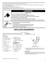
from a neighbor's phone. Follow the gas supplier's instructions. • If you cannot reach your gas supplier, call the fire department. - Installation and service must be performed by a qualified installer, service agency or the gas supplier. WARNING: Gas leaks cannot always be detected by smell - Maytag MGR8800DS | Installation Guide - Page 3
or wall. • Slide range back so rear range foot is under anti-tip bracket. • See installation instructions for details. INSTALLATION REQUIREMENTS Tools and Parts Gather the required tools and parts before starting installation. Parts supplied Read and follow the instructions provided with any - Maytag MGR8800DS | Installation Guide - Page 4
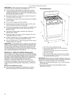
E. 25 64.6 cm) depth. Back of range to front of cooktop** F. Model/serial rating plate (located on the oven frame behind the top right side of the oven door) IMPORTANT: Range must be level after installation. Follow the instructions in the "Level Range" section. Using the cooktop as a reference - Maytag MGR8800DS | Installation Guide - Page 5
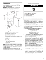
extension cord. Failure to follow these instructions can result in death, fire, or electrical shock. IMPORTANT: The range must be electrically grounded in accordance outlet provides 120-volt power and is correctly grounded. ■ This gas range is not required to be plugged into a GFCI (Ground-Fault - Maytag MGR8800DS | Installation Guide - Page 6
instructions. Type of Gas Natural gas: This range is design-certified by CSA International for use with Natural gas or, after proper conversion, for use with LP gas. ■ This range is factory set for use with Natural gas. See "Gas Conversions" section. The model/serial rating plate located on the oven - Maytag MGR8800DS | Installation Guide - Page 7
or lower The range must be isolated from the gas supply piping system by closing its individual manual shutoff valve during any pressure testing of the gas supply piping system at test pressures equal to or less than ½ psi (3.5 kPa). INSTALLATION INSTRUCTIONS Unpack Range WARNING Excessive Weight - Maytag MGR8800DS | Installation Guide - Page 8
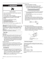
to continue installing the range using the following installation instructions. Make Gas Connection WARNING Explosion Hazard Use a new CSA International approved gas supply line. Install a shut-off valve. Securely tighten all gas connections. If connected to LP, have a qualified person make - Maytag MGR8800DS | Installation Guide - Page 9
Manual gas shutoff valve G. ½" or ¾" gas pipe H. Nipple I. Union J. 90° elbow Typical flexible connection 1. Apply pipe-joint compound made for use with LP gas follow these instructions can result in death, fire, or electrical shock. 5. Plug into a grounded 3 prong outlet. 6. Slide range into final - Maytag MGR8800DS | Installation Guide - Page 10
between the range and the mounting wall. Changes to the gas supply must be performed by a qualified service technician. If you need assistance or service, refer to the "Assistance or Service" section of the Use and Care Guide, or the cover or "Warranty" section of the User Instructions, for contact - Maytag MGR8800DS | Installation Guide - Page 11
gas line. If burners do not light properly: ■ Turn cooktop control knob to the "OFF" position. ■ Check that the range "low" flame needs to be adjusted: A A. Screws B. Oven Guide or User Instructions for proper operation of the oven controls. Adjust Oven Bake Burner Flame (if needed) 1. On models - Maytag MGR8800DS | Installation Guide - Page 12
(on some models) Remove all items from inside the warming drawer or premium storage drawer, and allow the range to cool completely the Use and Care Guide or User Instructions for proper operation of the oven controls. Adjust Oven Broil Burner Flame (if needed) Look through oven window to check broil - Maytag MGR8800DS | Installation Guide - Page 13
grounded 3 prong outlet. ■ Electrical supply is connected. ■ See "Troubleshooting" in the Use and Care Guide or User Instructions. 8. When the range has been on for 5 minutes, check for heat. If the range is cold, turn off the range and check that the gas supply line shutoff valve is open. ■ If the - Maytag MGR8800DS | Installation Guide - Page 14
instructions can result in death or serious burns to children and adults. 1. Turn the manual shutoff valve to the closed position. B A C A. To range B. Manual shutoff valve "closed" position C. Gas supply line 2. Unplug range or disconnect power. To Convert Gas Pressure Regulator (Natural Gas to LP - Maytag MGR8800DS | Installation Guide - Page 15
0.85 mm 0.70 mm L107 L99 L85 L70 NOTE: Refer to the Model Number and Serial Number Plate located on the oven frame behind the top right side of the oven door for proper sizing of spuds for each burner location. 5. Place Natural gas orifice spuds in the cardboard orifice spud holder. 6. Replace the - Maytag MGR8800DS | Installation Guide - Page 16
bottom panel toward the front frame and lower the rear of the oven bottom panel into the oven. 11. Reattach the oven bottom panel with screws. To Convert Oven Broil Burner (Natural Gas to LP Gas) 1. Remove the screw from the broil burner. 2. Remove the broil burner from the broil burner orifice hood - Maytag MGR8800DS | Installation Guide - Page 17
cm) to ½" (1.3 cm) long. The outer cone is not as distinct as the inner cone. LP gas flames have a slightly yellow tip. 3. Refer to "Complete Installation" in the "Installation Instructions" section of this manual to complete this procedure. NOTE: Make sure to save the orifices that have just been - Maytag MGR8800DS | Installation Guide - Page 18
N180 N155 N140 N110 NOTE: Refer to the Model Number and Serial Number Plate located on the oven frame behind the top right side of the oven door for proper sizing of spuds for each burner location. 5. Place LP gas orifice spuds in plastic parts bag for future use and keep with package containing - Maytag MGR8800DS | Installation Guide - Page 19
or Premium Storage Drawer" section. 8. Replace the oven door. See the "Oven Door" section. 9. Replace the oven racks. Complete Installation (LP Gas to Natural Gas) 1. Refer to the "Make Gas Connection" section for properly connecting the range to the gas supply. 2. Refer to the "Electronic Ignition - Maytag MGR8800DS | Installation Guide - Page 20
entretien doivent être effectués par un installateur qualifié, une agence de service ou le fournisseur de gaz. AVERTISSEMENT : L'odorat ne permet pas gaz local. En cas de détection d'une fuite de gaz, exécuter les instructions "Que faire dans le cas d'une odeur de gaz". IMPORTANT : Ne pas installer - Maytag MGR8800DS | Installation Guide - Page 21
Fixer la bride antibasculement au plancher ou au mur, conformément aux instructions d'installation. Faire glisser de nouveau la cuisinière de façon à antibasculement n'est pas installée et engagée. Le non-respect de ces instructions peut causer un décès ou des brûlures graves aux enfants et aux - Maytag MGR8800DS | Installation Guide - Page 22
cessaires. Lire et suivre les instructions fournies avec les outils indiqués Part 280). Lorsque cette norme n'est pas applicable, l'installation doit satisfaire aux critères de la norme Standard for Manufactured Home Installations, ANSI A225.1/NFPA 501A ou aux dispositions des codes locaux. Au Canada - Maytag MGR8800DS | Installation Guide - Page 23
du four, derrière le côté supérieur droit de la porte du four) IMPORTANT : La cuisinière doit être d'aplomb après l'installation. Suivre les instructions de la section "Réglage de l'aplomb de la cuisinière". Il n'est pas recommandé d'utiliser la table de cuisson comme référence pour établir l'aplomb - Maytag MGR8800DS | Installation Guide - Page 24
satisfaire aux prescriptions de la plus récente édition du : National Fuel Gas Code ANSI Z223.1 (American National Standard), ou CAN/CGA B149 (édition tests de fuite de la cuisinière doivent être effectués selon les instructions du fabricant. Type de gaz Gaz naturel : La conception de cette cuisini - Maytag MGR8800DS | Installation Guide - Page 25
on doit réduire le débit thermique indiqué de 4 % pour chaque tranche de 1000 pi (304,8 m) au-dessus du niveau de la mer (pas applicable au Canada). Tests de pressurisation de la canalisation de gaz On doit tester le détendeur sous une pression supérieure d'au moins 1" à la pression de la tubulure - Maytag MGR8800DS | Installation Guide - Page 26
é ou une pince. C A Risque du poids excessif Utiliser deux ou plus de personnes pour déplacer et installer la cuisinière. Le non-respect de cette instruction peut causer une blessure au dos ou d'autre blessure. 1. Ôter les matériaux d'emballage, le ruban adhésif et le film protecteur de la cuisini - Maytag MGR8800DS | Installation Guide - Page 27
personnel autorisé de chauffage, le personnel autorisé d'une compagnie de gaz, et le personnel d'entretien autorisé. Le non-respect de ces instructions peut causer un décès, une explosion ou un incendie. Positionnement par l'arrière Montage mural Positionnement par l'avant En diagonale (2 options - Maytag MGR8800DS | Installation Guide - Page 28
enlever la broche de liaison à la terre. Ne pas utiliser un adaptateur. Ne pas utiliser un câble de rallonge. Le non-respect de ces instructions peut causer un décès, un incendie ou un choc électrique. A. Détendeur B. Appliquer un composé d'étanchéité C. Raccord d'adaptation (avec filetage mâle de - Maytag MGR8800DS | Installation Guide - Page 29
ère si la bride antibasculement n'est pas installée et engagée. Consulter la section "Assistance ou Service" du guide d'utilisation et d'entretien, la couverture ou la section "Garantie" des instructions d'utilisation pour obtenir les coordonnées des personnes à contacter. Réglage de l'aplomb de la - Maytag MGR8800DS | Installation Guide - Page 30
ne survenir qu'après 50 à 60 secondes. Un dispositif d'allumage électronique est utilisé pour l'allumage des brûleurs du four et du gril. Consulter le Guide d'utilisation et d'entretien pour le bon fonctionnement des commandes du four. Réglage de la taille des flammes sur le brûleur du four (le cas - Maytag MGR8800DS | Installation Guide - Page 31
Le brûleur du four devrait s'allumer en moins de 8 secondes; dans certaines conditions, l'allumage peut ne survenir qu'après 50 à 60 secondes. Consulter le Guide d'utilisation et d'entretien pour le bon fonctionnement des commandes du four. Réglage de la taille des flammes sur le brûleur du gril (le - Maytag MGR8800DS | Installation Guide - Page 32
la porte du four pour une utilisation normale. Toutefois, si la dépose est nécessaire, s'assurer que le four est éteint et froid. Puis, suivre ces instructions. La porte du four est lourde. Dépose : 1. Ouvrir la porte du four complètement. 2. Pincer le loquet de charnière entre les deux doigts et - Maytag MGR8800DS | Installation Guide - Page 33
et contacter un technicien qualifié. Si vous avez besoin d'assistance ou de service : Veuillez consulter la section "Assistance ou service" dans le Guide d'utilisation et d'entretien ou la page de couverture des instructions d'utilisation, ou contacter le revendeur qui vous a vendu la cuisinière - Maytag MGR8800DS | Installation Guide - Page 34
Fixer la bride antibasculement au plancher ou au mur, conformément aux instructions d'installation. Faire glisser de nouveau la cuisinière de façon bride antibasculement n'est pas installée et engagée. Le non-respect de ces instructions peut causer un décès ou des brûlures graves aux enfants et aux - Maytag MGR8800DS | Installation Guide - Page 35
antihoraire et soulever pour enlever le gicleur. Conserver à part le gicleur du brûleur. C A D LP C Vue de côté - après A. Capuchon en installer le couvercle de plastique par-dessus le capuchon du détendeur. LP B A. Gicleur B. Support du gicleur C. Vis D. Électrode d'étincelle 4. Retirer le - Maytag MGR8800DS | Installation Guide - Page 36
Gicleur pour propane pour brûleurs de surface Puissance thermique Couleur Taille Code d'identification 14 000 BTU 11 000 BTU 8 000 BTU 5 000 BTU Jaune/Orange Jaune/Marron Jaune/Noir Jaune/Blanc 1,07 mm 0,99 mm 0,85 mm 0,70 mm L107 L99 L85 L70 REMARQUE : Voir la plaque signalétique située - Maytag MGR8800DS | Installation Guide - Page 37
Fixer la bride antibasculement au plancher ou au mur, conformément aux instructions d'installation. Faire glisser de nouveau la cuisinière de façon bride antibasculement n'est pas installée et engagée. Le non-respect de ces instructions peut causer un décès ou des brûlures graves aux enfants et aux - Maytag MGR8800DS | Installation Guide - Page 38
sens antihoraire et soulever pour enlever le gicleur. Conserver à part le gicleur du brûleur. C A D B situé sous le capuchon. Vue de côté - avant A LP LP B D E NG NG C Vue de côté - après remplacement des gicleurs. 38 A. Gicleur B. Support du gicleur C. Vis D. Électrode d'étincelle - Maytag MGR8800DS | Installation Guide - Page 39
Conversion du brûleur de cuisson au four (de gaz propane à gaz naturel) 1. Retirer les grilles du four. 2. Ôter 2 vis à l'arrière de la partie inférieure du four. 3. Soulever l'arrière de la partie inférieure du four vers le haut et l'arrière jusqu'à ce que l'avant du panneau se trouve hors du cadre - Maytag MGR8800DS | Installation Guide - Page 40
jaune. 3. Voir le paragraphe "Achever l'installation" de la section "Instructions d'installation" du présent manuel pour achever cette procédure. ©2012 Whirlpool Corporation. Used under license in Canada. All rights reserved. Utilisée sous licence au Canada. Tous droits réservés. 10/12 Printed in
-
 1
1 -
 2
2 -
 3
3 -
 4
4 -
 5
5 -
 6
6 -
 7
7 -
8
-
9
-
10
-
11
-
12
-
13
-
14
-
15
-
16
-
17
-
18
-
19
-
20
-
21
-
22
-
23
-
24
-
25
-
26
-
27
-
28
-
29
-
30
-
31
-
32
-
33
-
34
-
35
-
36
-
37
-
38
-
39
-
40
 |
 |

INSTALLATION INSTRUCTIONS
30" (76.2 CM) FREESTANDING GAS RANGES
INSTRUCTIONS D’INSTALLATION DES CUISINIÈRES À GAZ
AUTOPORTANTES DE 30" (76,2 CM)
Table of Contents/Table des matières
RANGE SAFETY
.............................................................................
2
INSTALLATION REQUIREMENTS
................................................
3
Tools and Parts
............................................................................
3
Location Requirements
................................................................
4
Electrical Requirements
...............................................................
5
Gas Supply Requirements
...........................................................
6
INSTALLATION INSTRUCTIONS
..................................................
7
Unpack Range
..............................................................................
7
Install Anti-Tip Bracket
.................................................................
8
Make Gas Connection
.................................................................
8
Verify Anti-Tip Bracket Is Installed and Engaged
......................
10
Level Range
................................................................................
10
Electronic Ignition System
.........................................................
11
Warming Drawer or Premium Storage Drawer
..........................
12
Storage Drawer
..........................................................................
13
Oven Door
..................................................................................
13
Complete Installation
.................................................................
13
GAS CONVERSIONS
....................................................................
14
LP Gas Conversion
....................................................................
14
Natural Gas Conversion
.............................................................
17
SÉCURITÉ DE LA CUISINIÈRE
...................................................
20
EXIGENCES D’INSTALLATION
...................................................
22
Outillage et pièces
......................................................................
22
Exigences d'emplacement
.........................................................
22
Spécifications électriques
..........................................................
24
Spécifications de l’alimentation en gaz
.....................................
24
INSTRUCTIONS D'INSTALLATION
............................................
26
Déballage de la cuisinière
..........................................................
26
Installation de la bride antibasculement
....................................
26
Raccordement à la canalisation de gaz
.....................................
27
Vérifier que la bride antibasculement est bien
installée et engagée
...................................................................
28
Réglage de l'aplomb de la cuisinière
.........................................
29
Système d'allumage électronique
.............................................
29
Tiroir-réchaud ou tiroir de remisage de qualité
supérieure
...................................................................................
31
Tiroir de remisage
......................................................................
32
Porte du four
..............................................................................
32
Achever l’installation
..................................................................
33
CONVERSIONS POUR CHANGEMENT DE GAZ
......................
34
Conversion pour l'alimentation au propane
..............................
34
Conversion pour l'alimentation au gaz naturel
..........................
37
IMPORTANT:
Installer:
Leave installation instructions with the homeowner.
Homeowner:
Keep installation instructions for future reference.
IMPORTANT :
Installateur :
Remettre les instructions d'installation au propriétaire.
Propriétaire :
Conserver les instructions d'installation pour référence ultérieure.
W10553363A