Maytag MMV1174FW Installation Guide
Maytag MMV1174FW Manual
 |
View all Maytag MMV1174FW manuals
Add to My Manuals
Save this manual to your list of manuals |
Maytag MMV1174FW manual content summary:
- Maytag MMV1174FW | Installation Guide - Page 1
from the illustration in these installation instructions. Table of Contents MICROWAVE HOOD COMBINATION SAFETY 1 INSTALLATION REQUIREMENTS MICROWAVE HOOD COMBINATION SAFETY Your safety and the safety of others are very important. We have provided many important safety messages in this manual - Maytag MMV1174FW | Installation Guide - Page 2
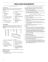
tools and parts before starting installation. Read and follow the instructions provided with any tools listed here. ■■ Measuring tape ■■ within cabinet opening. ■■ Support for weight of 150 lbs (68 kg), which includes microwave oven and items placed inside the microwave oven and upper cabinet. - Maytag MMV1174FW | Installation Guide - Page 3
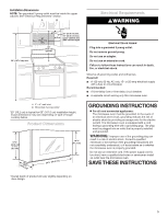
.3 cm) (42.15U6c³p⁄m₄t"o)* 29⁷⁄₈" (76.0 cm) *Overall depth of product will vary slightly depending on door design. GROUNDING INSTRUCTIONS I For all cord connected appliances: The microwave oven must be grounded. In the event of an electrical short circuit, grounding reduces the risk of electric - Maytag MMV1174FW | Installation Guide - Page 4
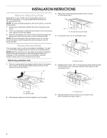
INSTRUCTIONS Remove Mounting Plate Depending on your model, the mounting plate may be in the foam packaging, or it may be attached to the back of the microwave oven. NOTE: To avoid possible damage to the work surface, cover the work surface. 1. Remove any remaining contents from the microwave - Maytag MMV1174FW | Installation Guide - Page 5
7. Reattach damper plate. Make sure damper plate tabs are inserted into the slots in the top of the microwave oven. A B C 6. Reattach blower motor to back of microwave oven with 2 screws removed in Step 3 of "Wall Venting Installation Only." Securely tighten screws. NOTE: If blower motor is not - Maytag MMV1174FW | Installation Guide - Page 6
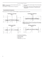
studs exist within the cabinet opening, do not install the microwave oven. See illustrations in "Possible Wall Stud Configurations." holes (on mounting plate) B. Cabinet opening vertical centerline C. Wall stud centerlines D. Holes for lag screws E. Support tabs F. Mounting plate center markers 6 - Maytag MMV1174FW | Installation Guide - Page 7
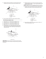
Mark Rear Wall The microwave oven must be installed on a minimum of 1 wall stud, preferably 2, each other. They must each be 14¹⁄₈" (35.9 cm) from the centerline. 5. With the support tabs facing forward (see illustrations in "Locate Wall Stud(s)" section), align the mounting plate center markers to - Maytag MMV1174FW | Installation Guide - Page 8
on at least 1 wall stud as well as at both ends. 1. With the support tabs of the mounting plate facing forward, insert 3/16-24 x 3" round-head bolts cabinet bottom. The template has trim lines to use as guides. ■■ If the wall behind the microwave oven (as installed) has a partial wall covering (for - Maytag MMV1174FW | Installation Guide - Page 9
oven B. Damper assembly C. Damper blade D. Sheet metal screws 3. Secure damper assembly with 2 sheet metal screws. A B A. Mounting plate B. Support tabs 4. With front of microwave oven still tilted, thread power supply cord through the power supply cord hole in the bottom of the upper cabinet - Maytag MMV1174FW | Installation Guide - Page 10
vent fan and exhaust by operating the vent fan. 5. If the microwave oven does not operate: ■■ Check that a household fuse has not problem continues, call an electrician. ■■ Check that the power supply cord is plugged into a grounded 3 prong outlet. ■■ See the User Instructions for troubleshooting - Maytag MMV1174FW | Installation Guide - Page 11
the roof, and rectangular to round transition is used, be sure there is at least 3" (7.6 cm) of clearance between the top of the microwave oven and the transition piece. See "Rectangular to Round Transition" illustration. Rectangular to Round Transition NOTE: The minimum 3" (7.6 cm) clearance must - Maytag MMV1174FW | Installation Guide - Page 12
ASSISTANCE Call your authorized dealer or service center. When you call, you will need the microwave oven model number and serial number visit our website listed in the User Guide. Accessories Filler Panel Kits are available from your dealer to use when installing this microwave oven in a 36" (91.4
-
 1
1 -
 2
2 -
 3
3 -
 4
4 -
 5
5 -
 6
6 -
 7
7 -
8
-
9
-
10
-
11
-
12
 |
 |
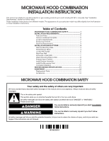
MICROWAVE HOOD COMBINATION
INSTALLATION INSTRUCTIONS
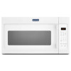
This product is suitable for use above electric or gas cooking products up to and including 36" (91.4 cm) wide. See “Installation
Requirements” section for further notes.
These installation instructions cover different models. The appearance of your particular model may differ slightly from the illustration
in these installation instructions.
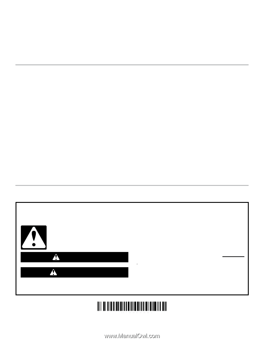
MICROWAVE HOOD COMBINATION SAFETY
You can be killed or seriously injured if you don't immediately
You
can be killed or seriously injured if you don't follow
All safety messages will tell you what the potential hazard is, tell you how to reduce the chance of injury, and tell you what can
happen if the instructions are not followed.
Your safety and the safety of others are very important.
We have provided many important safety messages in this manual and on your appliance. Always read and obey all safety
messages.
This is the safety alert symbol.
This symbol alerts you to potential hazards that can kill or hurt you and others.
All safety messages will follow the safety alert symbol and either the word “DANGER” or “WARNING.”
These words mean:
follow instructions.
instructions.
DANGER
WARNING
MICROWAVE HOOD COMBINATION SAFETY
............................
1
INSTALLATION REQUIREMENTS
.................................................
2
Tools and Parts
.............................................................................
2
Remove Cardboard Template
......................................................
2
Location Requirements
................................................................
2
Product Dimensions
.....................................................................
3
Electrical Requirements
...............................................................
3
INSTALLATION INSTRUCTIONS
...................................................
4
Remove Mounting Plate
...............................................................
4
Rotate Blower Motor
....................................................................
4
Locate Wall Stud(s)
......................................................................
6
Mark Rear Wall
.............................................................................
7
Drill Holes in Rear Wall
.................................................................
7
Attach Mounting Plate to Wall
.....................................................
8
Prepare Upper Cabinet
................................................................
8
Install Damper Assembly
.............................................................
9
Install the Microwave Oven
..........................................................
9
Complete Installation
.................................................................
10
VENTING DESIGN SPECIFICATIONS
.........................................
11
ASSISTANCE
................................................................................
12
Replacement Parts
.....................................................................
12
Accessories
................................................................................
12
Table of Contents
W10823831A