Maytag MVWB765FC Owners Manual
Maytag MVWB765FC Manual
 |
View all Maytag MVWB765FC manuals
Add to My Manuals
Save this manual to your list of manuals |
Maytag MVWB765FC manual content summary:
- Maytag MVWB765FC | Owners Manual - Page 1
Care 3 Nonuse and Vacation Care 4 Winter Storage Care 4 Transporting Your Washer 4 Reinstalling/Using Washer Again 4 Installation Instruction. s 5 Requirements 5 Tools and Parts 5 Location Requirements 5 Drain System 6 Electrical Requirements 6 Installation 7 Unpacking 7 Connect Drain - Maytag MVWB765FC | Owners Manual - Page 2
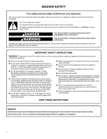
water system has not been used for such a period, before using a washing machine, turn on all hot-water faucets and let the water flow from any part of the appliance or attempt any servicing unless specifically recommended in the usermaintenance instructions or in published user-repair instructions - Maytag MVWB765FC | Owners Manual - Page 3
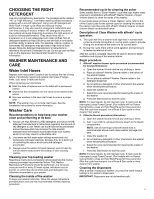
, once per month or every 30 wash cycles, whichever occurs sooner, to control the rate at which soils and detergent may otherwise accumulate in your washer. Cleaning the inside of the washer To keep your washer odor-free, follow the usage instructions provided above and use this recommended monthly - Maytag MVWB765FC | Owners Manual - Page 4
Instructions to locate, level, and connect washer. 2. Before using again, run washer through the following recommended procedure: To use washer again 5. See your online Cycle Guide for information about which cycle(s) to run your washer through to clean washer and remove antifreeze, if used - Maytag MVWB765FC | Owners Manual - Page 5
Drain hose with clamp, U-form, and cable tie Parts Needed: (if not supplied with washer) Inlet hoses with flat washers NOTE: Various inlet hose options are available; check your Quick Start Guide for ordering information. NOTE: All 27″ wide washers should have 19″ clearance, while all 29″ wide - Maytag MVWB765FC | Owners Manual - Page 6
All dimensions show recommended spacing allowed, except for closet door ventilation openings, which are the minimum required. This washer has been tested for installation with spacing of 0″ (0 mm) clearance on the sides. Consider allowing more space for ease of installation and servicing, and - Maytag MVWB765FC | Owners Manual - Page 7
. Check with a qualified electrician or service representative if you are in doubt as instructions included with the sound shield to install it at this time. To avoid damaging floor, place cardboard supports from shipping carton on floor behind washer. Tip washer back and place on cardboard supports - Maytag MVWB765FC | Owners Manual - Page 8
directions. See "Tools and Parts." It is the responsibility of the installer to install and secure the drain hose into the provided plumbing/drain in a manner that will avoid the drain hose coming out of and leaking from the plumbing/drain. Connect Inlet Hoses Washer must be connected to water - Maytag MVWB765FC | Owners Manual - Page 9
. Check for leaks Move the washer to its final location. Place a level on top edges of washer. Use side seam as a guide to check levelness of sides. may enter washer. It will drain later. 05-Aug-2019 13:05:14 EDT | RELEASED 9 In some European factories the letter "W" of the part code mentioned - Maytag MVWB765FC | Owners Manual - Page 10
4″ (102 mm) with a wood block or similar object that will support weight of washer. WARNING Complete Installation Checklist � Check electrical requirements. Be sure you have correct electrical supply and recommended grounding method. � Check that all parts are now installed. If there is an extra - Maytag MVWB765FC | Owners Manual - Page 11
-respect des instructions. IMPORTANTES INSTRUCTIONS DE SÉCURIT porte de l'appareil avant de le retirer du service ou de le mettre au rebut. Ne support de thermostat lorsque l'appareil est sous tension. 05-Aug-2019 13:05:14 EDT | RELEASED 11 In some European factories the letter "W" of the part - Maytag MVWB765FC | Owners Manual - Page 12
libre de toute odeur, suivre les instructions d'utilisation indiquées ci-dessus et équipés d'un programme « Clean Washer » (nettoyage de la laveuse) qui de nettoyage de la laveuse, consulter le guide de programmes en ligne pour connaître the part code mentioned herein will be automatically replaced by - Maytag MVWB765FC | Owners Manual - Page 13
le nettoyer avec une lingette de nettoyage de machine affresh® ou un chiffon humide et sécher avec un câble de rallonge. Le non-respect de ces instructions peut causer un décès, un incendie ou un choc é letter "W" of the part code mentioned herein will be automatically replaced by the - Maytag MVWB765FC | Owners Manual - Page 14
pour une charge de taille moyenne. INSTRUCTIONS D'INSTALLATION SPÉCIFICATIONS Outillage et pi mentaires. Pour commander, consulter les coordonnées indiquées dans le guide de démarrage rapide. Si vous avez : Égout surélevé the part code mentioned herein will be automatically replaced by the number " - Maytag MVWB765FC | Owners Manual - Page 15
endos en mousse. � Un plancher capable de supporter le poids total de 315 lb (143 Toutes les dimensions représentent les dégagements recommandés permis achetés séparément; consulter le guide de démarrage rapide pour les renseignements part code mentioned herein will be automatically replaced by the number - Maytag MVWB765FC | Owners Manual - Page 16
un adaptateur. Ne pas utiliser un câble de rallonge. Le non-respect de ces instructions peut causer un décès, un incendie ou un choc électrique. Une source d'alimentation factories the letter "W" of the part code mentioned herein will be automatically replaced by the number "4000" - Maytag MVWB765FC | Owners Manual - Page 17
laveuse vers l'arrière et la placer sur les supports en carton. Retirer la base d'expédition ( à l'étape 7. Des pièces supplémentaires avec des instructions distinctes s'avèreront peut-être nécessaires. Voir la section letter "W" of the part code mentioned herein will be automatically replaced by - Maytag MVWB765FC | Owners Manual - Page 18
permettre une fixation correcte des tuyaux à la laveuse. 18 05-Aug-2019 13:05:14 EDT | RELEASED In some European factories the letter "W" of the part code mentioned herein will be automatically replaced by the number "4000" (e.g. "W12345678" becomes "400012345678") - Maytag MVWB765FC | Owners Manual - Page 19
sur les bords supérieurs de la laveuse. Utiliser une rive latérale comme guide pour déterminer l'aplomb des côtés. Vérifier l'aplomb de l'avant à l'aide some European factories the letter "W" of the part code mentioned herein will be automatically replaced by the number "4000" (e.g. - Maytag MVWB765FC | Owners Manual - Page 20
adaptateur. Ne pas utiliser un câble de rallonge. Le non-respect de ces instructions peut causer un décès, un incendie ou un choc électrique. 15. Brancher sur éeseEruvréosp. eToadnofsaclotsordieesretchheoslertetesrer"vWad"oosf. the part code mentioned herein will be automatically 05-Aug
-
 1
1 -
 2
2 -
 3
3 -
 4
4 -
 5
5 -
 6
6 -
 7
7 -
8
-
9
-
10
-
11
-
12
-
13
-
14
-
15
-
16
-
17
-
18
-
19
-
20
 |
 |
W11354658A
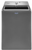
TOP
LOAD WASHER OWNER’S MANUAL
MANUEL DE L’UTILISATEUR DE LA LAVEUSE À
CHARGEMENT PAR LE DESSUS
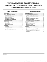
Table of Contents
WasherSafety
.........................................................
2
Washer Maintenance and Care
...............................
3
Water Inlet Hoses
...............................................
3
Washer Care
......................................................
3
Nonuse and Vacation Care
.................................
4
Winter Storage Care
...........................................
4
Transporting Your Washer
...................................
4
Reinstalling/Using Washer Again
.........................
4
Installation Instructions
. ..........................................
5
Requirements
..........................................................
5
Tools and Parts
..................................................
5
Location Requirements
.......................................
5
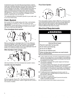
Drain System
.....................................................
6
Electrical Requirements
......................................
6
Installation
...............................................................
7
Unpacking
.........................................................
7
Connect Drain Hose
...........................................
8
Connect Inlet Hoses
...........................................
8
Level Washer
.....................................................
9
Complete Installation Checklist
..........................
10
Sécuritéde la laveuse
............................................
11
Entretienet réparation de la laveuse
.....................
12
Tuyaux d’arrivée d’eau
......................................
12
Entretien de la laveuse
.....................................
12
Non utilisation et entretien avant les
vacances
.........................................................
13
Entretien pour entreposage hivernal
..................
13
Transport de la laveuse
.....................................
13
Réinstallation/réutilisation de la laveuse
.............
13
Instructions d'installation
.........................................
14
Spécifications
........................................................
14
Outillage et pièces
............................................
14
Exigences d’emplacement
................................
14
Système de vidange
.........................................
15
Spécifications électriques
.................................
16
Installation
.............................................................
16
Déballage
........................................................
16
Raccordement du tuyau de vidange
...................
17
Raccordement des tuyaux d’alimentation
...........
18
Établissement de l'aplomb de la laveuse
............
19
Liste de vérification pour l’achèvement de
l’installation
......................................................
20
Table des matières
W11354659-SP
05-Aug-2019 13:05:14 EDT | RELEASED
In some European factories the letter "W" of the part code mentioned herein will be automatically
replaced by the number "4000" (e.g. "W12345678" becomes "400012345678")