NEC MT1075 MT1065/1075_1 IG
NEC MT1075 - XGA LCD Projector Manual
 |
UPC - 050927246272
View all NEC MT1075 manuals
Add to My Manuals
Save this manual to your list of manuals |
NEC MT1075 manual content summary:
- NEC MT1075 | MT1065/1075_1 IG - Page 1
and Right Bottom, Back and Left Ceiling Mount Dimensions Input Panel and Control Codes Pg. 1 Pg. 2 Pg. 3 Pg. 4 Pg. 5 Pg. 6 Pg. 7 NEC Solutions (America), Inc. Visual Systems v3.1 Product Description Type: 3 panel LCD projector, 1.0" p-Si TFT w/MLA Resolution: 1024 x 768 (4:3) 1024 x 576 (16 - NEC MT1075 | MT1065/1075_1 IG - Page 2
the relationship between projector position and the screen. Refer to the chart below for data. Distances are in inches. For millimeters multiply by 25.4. Ceiling Mounted Screen Top / Lens Ctr* C Throw Distance 4.4" 4.4" α B Screen Ctr Lens Offset from Mount Pipe Desktop 2.9" * lens set back - NEC MT1075 | MT1065/1075_1 IG - Page 3
projector position and the screen. Refer to the chart below for data. Distances are in inches. For millimeters multiply by 25.4. Ceiling Mounted Screen Top / Lens Ctr* C Throw Distance 4.4" 4.4" α B Screen Ctr Lens Offset from Mount Pipe Desktop 2.9" * lens .com MT1065/1075 Page 3 of 7 - NEC MT1075 | MT1065/1075_1 IG - Page 4
Dimensions The following drawings show the cabinet dimensions. Dimensions are in inches. For millimeters multiply by 25.4. IR SENSOR 12.71 6.28 2.21 INTAKE LAMP EXHAUST 13.14 4.92 3.63 IR SENSOR 3.09 5.48 5.14 4.53 3.49 www.necvisualsystems.com 3.19 IMAGE SENSOR MT1065/1075 Page 4 of 7 - NEC MT1075 | MT1065/1075_1 IG - Page 5
) The following drawings show the cabinet dimensions. Dimensions are in inches. For millimeters multiply by 25.4. IR SENSOR INTAKE MAX M4x8 FOR MOUNT IR SENSOR 10.63 9.92 10.27 3.50 3.39 0.35 2.38 INTAKE (AIR FILTER) 0.67 www.necvisualsystems.com 9.49 0.47 MT1065/1075 Page 5 of 7 - NEC MT1075 | MT1065/1075_1 IG - Page 6
Optional Ceiling Mount Dimensions (Model #: MT60CM) The following drawings show ceiling mount dimensions. Dimensions are in inches. For millimeters multiply by 25.4. 3.75 5.75 11.00 11.50 5.45 3.66 2.07 www.necvisualsystems.com MT1065/1075 Page 6 of 7 - NEC MT1075 | MT1065/1075_1 IG - Page 7
AUDIO B/Cb USB (PC) PC CARD REMOTE USB (MOUSE/HUB) H V AUDIO L/MONO R PC CONTROL RGB 2 IN RGB 1 IN RGB OUT AUDIO L/MONO R AUDIO L/MONO R S-VIDEO IN AUDIO VIDEO IN AUDIO Control Codes Function Code Data POWER ON 02H 00H 00H 00H 00H 02H POWER OFF 02H 01H 00H 00H 00H 03H
-
 1
1 -
 2
2 -
 3
3 -
 4
4 -
 5
5 -
 6
6 -
 7
7
 |
 |

NEC Solutions (America), Inc.
Visual Systems
MT1065/1075 Installation Guide
Used with 4:3 and 16:9 screens
v3.1
Contents
www.necvisualsystems.com
MT1065/1075
Page 1 of 7
Product Description, Lens Specs,
Screen/Aspect Ratio, Notes and Formulas
Pg. 1
Diagrams and Distance Charts,
4:3 Screens
Pg. 2
16:9 Screens
Pg. 3
Cabinet Dimensions, Top, Front and Right
Pg. 4
Bottom, Back and Left
Pg. 5
Ceiling Mount Dimensions
Pg. 6
Input Panel and Control Codes
Pg. 7
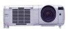
Product Description
Type:
3 panel LCD projector,
Brightness:
MT1065: 3400 ANSI lumens
1.0” p-Si TFT w/MLA
MT1075: 4200 ANSI lumens
Resolution:
1024 x 768 (4:3)
Dimensions:
13.14”(W) x 5.48”(H) x 12.71”(D)
1024 x 576 (16:9)
Weight:
13.0 lbs
Lens Specifications
Throw Ratio: 1.5 - 2.1:1(for 100” diagonal)
Focal Length: 30.8mm – 41.6mm
Offset Angle: 10.4
°
-13.9
°
(for 100” diagonal)
F/#:
1.74 – 2.18
Screen Sizes: 25”-500” diagonal (4:3)
Power Zoom / Power Focus (w/autofocus)
Screen/Aspect Ratio
Both 4:3 and 16:9 screens are fully supported
with proper aspect ratio control for both type sources using NEC developed
scaling technology. By selecting the screen type in the menus, Aspect Ratio control is reconfigured for that screen type.
•
For a 4:3 screen; select “4:3” in the “Screen” menu for proper aspect ratio control of 4:3 and 16:9 sources.
•
For a 16:9 screen; select “16:9” in the “Screen” menu for proper aspect ratio control of 4:3 and 16:9 sources.
*Factory default “Screen” setting is “4:3”.
Notes
For screen sizes not indicated on the projection charts, use the formulas below.
If a value in a chart does not match the results of the formulas, use the values in the chart.
The ceiling must be strong enough to support the projector and the installation must be in accordance with any local
building codes.
Distances are in inches, for millimeters multiply by 25.4.
Distances may vary
±
5%.
Formulas
The Projection Formulas use the image width for calculation. Image width is the same for all aspect ratios, only vertical image size
varies. For proper projector placement, determine the image width for a desired screen size. Use the Screen Formulas below to
calculate all screen dimensions. Plug in the image width for “W” in the Projection Formulas.
Refer to the diagrams and charts for popular screen sizes on page 2.
Definitions:
4:3 Screen Formulas:
W
= Image Width
W
= H x 4/3
H
= Image Height (Size)
H
= W x 3/4
B
= Vertical distance between lens center and screen center
Screen Diagonal
= W x 5/4
C
= Throw distance
α
= Projection angle
16:9 Screen Formulas:
W
= H x 16/9
Projection Formulas:
H
= W x 9/16
B
= 0.375W
Screen Diagonal
= W x 18.358/16
C
(wide) = 1.5419W – 1.922
C
(tele)
= 2.0738W – 1.922
Vertical Position for a 16:9 screen:
The Vertical Position adjustment moves the 16:9
α
(wide) = tan
-1
(B/C(wide))
image up and down in the unused portion of the 4:3 panel. This adjustment is only
α
(tele)
= tan
-1
(B/C(tele))
available when the projector is set for ‘16:9’ in the
‘
Screen’ menu. The range of Vertical
Position is dependent on aspect ratio and 3D Reform used. If 3D Reform is not used,
the approximate range of Vertical
P
osition is +/-0.167H (H=Screen Height) when using
a 16:9 screen.
Note:
To avoid premature lamp failure, do not tilt the front of the projector up or down by more than 75° from level. Tilting the front of the
projector up or down from 15° to 75° might reduce lamp life by up to 25%.