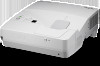
NEC NP-UM351W NP04WK1 Installation Manual
NEC NP-UM351W Manual
 |
View all NEC NP-UM351W manuals
Add to My Manuals
Save this manual to your list of manuals |
NEC NP-UM351W manual content summary:
- NEC NP-UM351W | NP04WK1 Installation Manual - Page 1
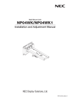
Wall Mount Unit NP04WK/NP04WK1 Installation and Adjustment Manual NP04WK-IAM-01 - NEC NP-UM351W | NP04WK1 Installation Manual - Page 2
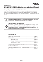
NP04WK/NP04WK1 Installation and Adjustment Manual Thank you for your purchase of this NEC wall mount unit. Please read this installation and adjustment manual carefully to ensure proper use. For a list of the supported projectors, please see the NEC website or NEC catalogs. The descriptions in the - NEC NP-UM351W | NP04WK1 Installation Manual - Page 3
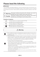
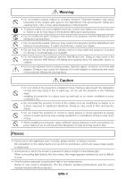
Symbol expresses compulsory actions. Concrete instructions are specified in figures. Warning be sure to do so as explained in this manual. The projector may fall and cause injury if to ensure sufficient strength to support the combined weight of the projector, the wall mount unit and so on for - NEC NP-UM351W | NP04WK1 Installation Manual - Page 4
to constant vibration. Extended vibration may cause loosening of the screws and result in the Wall Mount Unit and projector falling and causing injury. Also, it may cause breakdown of the projector. (For the ambient operating temperature, see the user's manual included with the projector.) ENG-3 - NEC NP-UM351W | NP04WK1 Installation Manual - Page 5
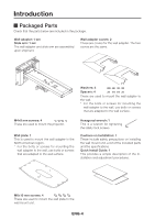
the safety lock screws. Cautions on Installation: 1 These include safety precautions on installing the wall mount unit, a list of the included parts and the specifications. Quick Install Guide: 1 This provides a simple description of the installation and adjustment procedures. M6×10 mm screws - NEC NP-UM351W | NP04WK1 Installation Manual - Page 6
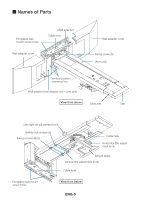
M Names of Parts Elongated wall mount screw holes (Wall adapter) Cable hole Wall adapter cover Wall adapter cover Fixing screw knob Safety lock screws (2) Fixing screws (B) (2) Cable hole Horizontal title adjustment knob (Mount plate) Vertical title adjustment knob Cable hole Elongated wall - NEC NP-UM351W | NP04WK1 Installation Manual - Page 7
following shows an external view of the wall mount unit, the positions of the wall adapter's wall mount screws and the amount of movement when mounting the projector. Units: mm 530 Center of wall adapter 60 572 (min.) to 994 (max.) (When wall plate mounted: 575 (min.) to 997 (max.) 422 (arm unit - NEC NP-UM351W | NP04WK1 Installation Manual - Page 8
as the optimum height of the projector and screen. Refer to the dimensions on the diagram to determine the position of installation, then perform the mounting procedure. CAUTION - When the screen is installed in front of the wall surface, the distance between the projector and the screen will be - NEC NP-UM351W | NP04WK1 Installation Manual - Page 9
31.5 65.8 38.8 73.2 Height between wall adapter's lower edge screw hole center and screen's upper edge - H1 (cm) 21.2 23.1 25.4 27.6 29.9 NP-UM330W/NP-UM280W Screen Size (D) W (width) x H2 (height) (cm) 58 124.9 78.1 60 129.2 80.8 70 150.8 94.2 80 172.3 107.7 90 193.9 121.2 100 - NEC NP-UM351W | NP04WK1 Installation Manual - Page 10
screen is to be installed and determine the position in which the wall mount unit is to be mounted. (See page ENG-7) - It is not possible to install in in "Be sure to read before installing" on page ENG-2 of these instructions. - Because the elevation angle of the projector's optical axis is large, - NEC NP-UM351W | NP04WK1 Installation Manual - Page 11
wall adapter with the M6 screws (or bolts). - For the position for mounting the wall adapter onto the wall and the dimensions, see "Dimensions of page ENG-7. - Be sure to fasten the screws at the center of the mount holes, as they will serve as the refer- ence points for the horizontal position - NEC NP-UM351W | NP04WK1 Installation Manual - Page 12
4. Insert the slide arm on the arm unit. Arm unit Slide arm 5. Attach the safety lock screws and fixing screws (B). (1) Use the included hexagonal wrench to securely tighten the two safety lock screws. (2) Leave the two fixing screws (B) loose. Tighten them after adjustments are made. (2) Fixing - NEC NP-UM351W | NP04WK1 Installation Manual - Page 13
6. Make the initial setting of the arm unit's vertical position. Upon shipment from the factory, the arm unit is set to the uppermost position. (1) Loosen the arm unit's fixing screw (A), then holding the arm unit's base, lower the arm unit to the lowermost position. (2) Temporarily fasten the - NEC NP-UM351W | NP04WK1 Installation Manual - Page 14
noise interference. (2) Upward cable hole Through-to-wall cable hole Downward cable hole Wall adapter Arm unit (1) Slide arm This completes installation of the projector. Mount the projector's cable cover and the wall adapter's covers after adjusting the projected image. ENG-13 - NEC NP-UM351W | NP04WK1 Installation Manual - Page 15
, then first move the projector's focus ring to roughly adjust the focus of the projected image. For instructions on projecting images, see "Projecting Images (Basic Operation)" of the user's manual (CD-ROM) supplied with the projector. - At "Installation" or "Settings" on the on-screen menu, select - NEC NP-UM351W | NP04WK1 Installation Manual - Page 16
2. Adjust the projector's tilt in the vertical direction. Turn the vertical tilt adjustment knob and adjust so that the left and right edges of the projected image are parallel. - The adjustment range is ±5°. Vertical tilt adjustment knob 3. Adjust the projector's tilt in the rotational direction. - NEC NP-UM351W | NP04WK1 Installation Manual - Page 17
screws (B). (2) Holding the slide arm's cap, move forward or back- ward to project the image over the entire screen. - When installed following the instructions under "Projection Distance and Screen Size", the image is projected at about the center. - The slide arm moves a maximum of 422 mm. - In - NEC NP-UM351W | NP04WK1 Installation Manual - Page 18
5. Adjust in the vertical direction. Loosen the fixing screw (A), then hold the base of the arm and move the arm upwards, targeting the reference line. Adjust so that the projected image is at the center of the screen surface. * If the projected image moves too far upwards with respect to the screen - NEC NP-UM351W | NP04WK1 Installation Manual - Page 19
7. Once the adjustments are completed, securely tighten all the screws that were loosened. 8. Attach the covers to the wall adapter. Cover (A) and cover (B) have the same shape. Attaching the covers (1) Push one of the covers onto the wall adapter. - The four tabs on the back of the cover fit into - NEC NP-UM351W | NP04WK1 Installation Manual - Page 20
9. Attach the cable cover to the projector. For instructions on attaching the cover, see the user's manual. WARNING - Do not bundle the power cord together with the cables and put it under the cable cover. Doing so could result in fire. This completes installation and adjustment. ENG-19 - NEC NP-UM351W | NP04WK1 Installation Manual - Page 21
below. Make holes with the proper depth and diameter for the screws to be used. Dimensional drawing for screw positions (units: mm) Wall adapter mount screw hole Wall mount hole Cable hole (1) Attach the included wall plate to a vertical member in the wall using screws (or bolts) (in 12 locations
-
 1
1 -
 2
2 -
 3
3 -
 4
4 -
 5
5 -
 6
6 -
 7
7 -
8
-
9
-
10
-
11
-
12
-
13
-
14
-
15
-
16
-
17
-
18
-
19
-
20
-
21
 |
 |
Wall Mount Unit
NP04WK/NP04WK1
Installation and Adjustment Manual
NP04WK-IAM-01