Netgear FS752TP FS752TP Installation Guide
Netgear FS752TP Manual
 |
View all Netgear FS752TP manuals
Add to My Manuals
Save this manual to your list of manuals |
Netgear FS752TP manual content summary:
- Netgear FS752TP | FS752TP Installation Guide - Page 1
Installation Guide NETGEAR ProSafe FS752TP Smart Switch™ Start Here Follow these instructions to install your FS752TP Smart Switch and connect it to the network. Then, consult the FS752TP Smart Switch Software Administration Manual for information about configuring features such as VLANs, spanning - Netgear FS752TP | FS752TP Installation Guide - Page 2
the FS752TP Smart Switch Software Administration Manual; a link to the online manual is on the Resource CD. If your network uses static IP addresses, be sure the switch and computer are configured with valid IP addresses that are in the same subnet. Technical Support Thank you for selecting NETGEAR
-
 1
1 -
 2
2
 |
 |
Installation Guide
NETGEAR ProSafe FS752TP Smart Switch™
Start Here
Follow these instructions to install your FS752TP Smart Switch and connect it to the
network. Then, consult the
FS752TP Smart Switch Software Administration Manual
for information about configuring features such as VLANs, spanning tree protocol
(STP), and Quality of Service (QoS).
Verify the Package Contents
When you open the box, verify that you received everything. The package includes
the following contents:
•
NETGEAR FS752TP Smart Switch
•
Rubber footpads for tabletop installation
•
Power cord
•
Rack-mount kit
•
Installation Guide (this document)
•
Resource CD that includes the NETGEAR Smart Control Center utility and
Hardware Installation Guide
. A link to the online
Software Administration
Manual
is on the Resource CD.
•
Warranty/Support Information Card.
Install the Switch
Prepare the site so that the mounting, access, power source, and environmental
requirements are met. If you have any questions about these requirements, see the
Hardware Installation Guide
for the FS752TP Smart Switch on your Resource CD.
Install the switch using one of the following methods:
•
On a flat surface: Put one of the rubber footpads that came with the switch on
each of the four concave spaces on the bottom of the switch.
•
In a rack: Use the rack-mount kit supplied with your switch to install the switch in
a 19-inch (48.3-centimeter) EIA standard equipment rack. Follow the installation
instructions included in the
Hardware Installation Guide.
Prepare the Administrative Computer
The administrative computer is the Windows-based system you use to perform the
initial switch setup and configuration. The administrative computer must have an
Ethernet adapter with a connection to the network and a CD drive.
Install the Smart Control Center Utility on the Computer
The NETGEAR Smart Control Center is a Windows-based application that
discovers NETGEAR Smart switches in your network and helps you to perform
management operations like firmware upgrades and IP address assignment.
To install the Smart Control Center utility on the administrative computer:
1.
Insert the Resource CD into your CD drive.
2.
Run the Setup program to install the Smart Control Center utility. The
Installation Wizard guides you through the installation.
Connect the Switch to the Network
If you use static IP addressing in your network, use the Smart Control Center utility
to configure a static IP address on the switch before connecting it to your network.
In the absence of a DHCP server, the switch uses a default IP address of
192.168.0.239 with a subnet mask of 255.255.255.0.
IMPORTANT!
The DHCP client on the switch is enabled by default. If you use
a DHCP server to provide the switch with an IP address, you
do not
need to configure the switch before connecting it to the
network.
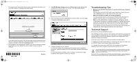
To configure the switch with a static IP address before connecting it to your network:
1.
Configure a static IP address on the administrative PC in the 192.168.0.0/24
subnet, for example 192.168.0.1.
2.
Use a category 5 (Cat5) unshielded twisted-pair (UTP) cable to connect the
Ethernet port on the PC to any front-panel RJ-45 port on the switch.
3.
Launch the Smart Control Center utility on the PC to discover the switch and
configure the appropriate static IP address for your network. For detailed
information about this step, see the online
FS752TP Smart Switch Software
Administration Manual
.
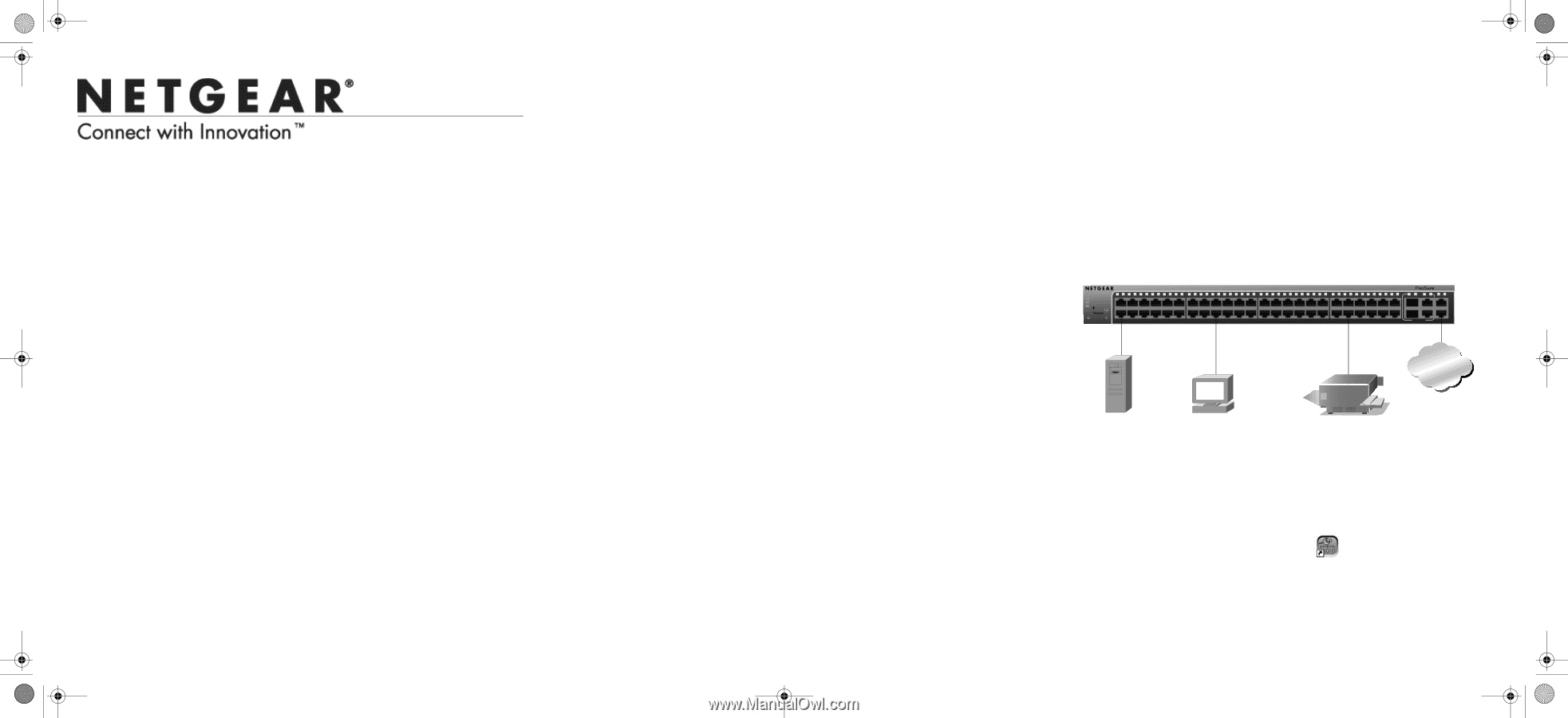
To connect the switch to the network:
1.
Connect each PC or other network device, such as a printer or server, to an
RJ-45 network port on the switch front panel.
Use Cat5 UTP cable terminated with an RJ-45 connector to make these
connections.
2.
Connect the switch to your network through a 1 Gbps uplink port.
3.
Connect one end of the supplied power cord to the switch and the other end to
an AC power source to power on the switch.
Discover the Switch with the Smart Control Center
Utility
To discover the FS752TP switch by using the Smart Control Center utility:
1.
Double-click the
Smart Control Center
icon
on your desktop or select
the application from the Windows Start menu Programs to run the utility.
2.
From the main Smart Control Center screen, click
Discover
to find your switch
in the network.
Make sure the switch has completed its boot cycle and is operational before you
click
Discover.
Ports 1-48, Link/Act Mode
—
Green=Link at 100M, Yellow=Link at 10M
Blink=ACT
Ports 49-52 Link/Act Mode
—
Green=1G, Yellow=10/100M
Blink=ACT
Power
Reset
Select
Fan
PoE Max
LED Mode
Yellow=PoE
Green=Link/ACT
Factory
Defaults
1
2
3
4
5
6
7
8
9
10
11
13
15
17
19
21
12
22
14
16
18
20
23
25
27
29
31
33
24
34
26
28
30
32
35
37
39
41
43
45
47
36
38
40
42
44
46
48
52
FS752TP
50F
50T
49F
49T
51
Servers
Computers
Printers
Ports 1-48, Link/Act Mode
—
Green=Link at 100M, Yellow=Link at 10M
Blink=ACT
Ports 49-52 Link/Act Mode
—
Green=1G, Yellow=10/100M
Blink=ACT
Combo Ports
Network
FS752TP IG 30Mar11.fm
Page 1
Thursday, March 31, 2011
12:17 PM