Netgear GS110TUP Hardware Installation Guide
Netgear GS110TUP Manual
 |
View all Netgear GS110TUP manuals
Add to My Manuals
Save this manual to your list of manuals |
Netgear GS110TUP manual content summary:
- Netgear GS110TUP | Hardware Installation Guide - Page 1
Hardware Installation Guide 10-Port Gigabit Ethernet Ultra60 PoE++ Smart Managed Pro Switch with 1 SFP and 1 Copper Uplink Models GS110TUP GS710TUP March 2020 202-12042-02 NETGEAR, Inc. 350 E. Plumeria Drive San Jose, CA 95134, USA - Netgear GS110TUP | Hardware Installation Guide - Page 2
à https://www.netgear.com/support/download/. (If this product is sold in Canada, you can access this document in Canadian French at https://www.netgear.com/support/download/.) For regulatory revised PoE++ overview on page 21. We added model GS110TUP. Initial publication for model GS710TUP. 2 - Netgear GS110TUP | Hardware Installation Guide - Page 3
Chapter 1 Introduction Overview 6 Features 6 Management options 8 Safety instructions and warnings 9 Chapter 2 Hardware Overview Model GS110TUP hardware 13 Model GS110TUP front panel with ports and LEDs 13 Model GS110TUP LEDs 14 Model GS110TUP back panel 15 Model GS710TUP hardware 15 Model - Netgear GS110TUP | Hardware Installation Guide - Page 4
model GS110TUP to a pole or another surface 36 Optional Step 5: Install an SFP transceiver module 37 Step 6: Connect devices to the switch 37 Step 7: Check the installation 38 Step 8: Apply power and check the LEDs 38 Step 9: Manage the switch 39 Chapter 5 Troubleshooting Troubleshooting chart - Netgear GS110TUP | Hardware Installation Guide - Page 5
installation guide complements the installation guide that came with your switch and applies to the following switches:. • Model GS110TUP. NETGEAR 10 instructions and warnings Note: For more information about the topics that are covered in this manual, visit the support website at netgear.com/support - Netgear GS110TUP | Hardware Installation Guide - Page 6
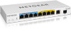
GS110TUP provides eight 10/100/1000BASE-T RJ-45 copper ports. Ports 1-4 support PoE++ and ports 5-8 support copper ports support nonstop 10/ supports the following key hardware features: • Four (model GS110TUP model GS110TUP, four ++ power budget: - For model GS110TUP, 240W across all active PoE++ and - Netgear GS110TUP | Hardware Installation Guide - Page 7
LACP) - IEEE 802.1ab LLDP - IEEE 802.1p Class of Service (QoS) - IEEE 802.1D Spanning Tree Protocol (STP) - IEEE ports. • Auto Uplink technology support for all ports. • Automatic PoE status LEDs and system PoE Max LED. • NETGEAR green power-saving features: - Energy efficiency mode that fully - Netgear GS110TUP | Hardware Installation Guide - Page 8
user manual, which you can download from netgear.com/support/download/. Note: If you plan to use the NETGEAR Insight troubleshoot the switch and the network. For more information about NETGEAR Insight, visit netgear.com/insight and see the NETGEAR knowledge base articles at netgear.com/support Guide - Netgear GS110TUP | Hardware Installation Guide - Page 9
If you use the NETGEAR Insight app or the NETGEAR Insight Mobile App The NETGEAR Insight server. Safety instructions and warnings NETGEAR product, which might not be covered by NETGEAR's warranty, to the extent permissible by applicable law. • Observe and follow service markings: - Do not service - Netgear GS110TUP | Hardware Installation Guide - Page 10
system components, and never operate the product in a wet environment. If the system gets wet, see the appropriate section in your troubleshooting guide, or contact your trained service provider. • Do not push any objects into the openings of your system. Doing so can cause fire or electric shock by - Netgear GS110TUP | Hardware Installation Guide - Page 11
uses a power adapter: - If you were not provided with a power adapter, contact your local NETGEAR reseller. - The power adapter must be rated for the product and for the voltage and current marked Always follow your local and national wiring rules. Introduction 11 Hardware Installation Guide - Netgear GS110TUP | Hardware Installation Guide - Page 12
2 Hardware Overview This chapter describes the switch hardware features. The chapter includes the following sections: • Model GS110TUP hardware • Model GS710TUP hardware • Switch hardware interfaces 12 - Netgear GS110TUP | Hardware Installation Guide - Page 13
GS110TUP hardware Model GS110TUP GS110TUP. Figure 1. Model GS110TUP front panel From left to right, the front panel of model GS110TUP provides the following components: • Power LED (see Model GS110TUP LEDs on page 14). • PoE Max LED (see Model GS110TUP see Model GS110TUP LEDs on Model GS110TUP LEDs on - Netgear GS110TUP | Hardware Installation Guide - Page 14
GS110TUP. Table 1. LEDs on the front panel of model GS110TUP LED Description Power LED Solid green. The switch is powered on and operating normally. If you changed the management mode of the switch to NETGEAR or receiving packets at 1 Gbps. Hardware Overview 14 Hardware Installation Guide - Netgear GS110TUP | Hardware Installation Guide - Page 15
came in the switch package. The following figure shows the back panel of model GS110TUP. Figure 2. Model GS110TUP back panel Model GS710TUP hardware Model GS710TUP provides eight 60W PoE++ (IEEE 802.3bt status (see Model GS710TUP LEDs on page 16). Hardware Overview 15 Hardware Installation Guide - Netgear GS110TUP | Hardware Installation Guide - Page 16
yet connected to the Insight cloud management server. Solid blue. The management mode of the switch is NETGEAR Insight, the switch is added to an Insight managed network, and the switch is connected to the to 8. Solid amber. A PoE fault occurred. Hardware Overview 16 Hardware Installation Guide - Netgear GS110TUP | Hardware Installation Guide - Page 17
BASE-T Ethernet connectivity All RJ-45 copper ports support autosensing. When you insert a cable into an duplex or full-duplex) of the attached device. All ports support a Cat 5e cable (or higher-rated Ethernet cable) devices, all RJ-45 ports support Auto Uplink technology. This technology - Netgear GS110TUP | Hardware Installation Guide - Page 18
GS110TUP, RJ-45 copper ports 1-4 support PoE++ and RJ-45 copper ports 5-8 support PoE+. On model GS710TUP, RJ-45 copper ports 1-8 support supports the NETGEAR SFP transceiver modules that are listed in the following table. Table 3. Supported about NETGEAR SFP transceiver modules, visit netgear.com/ - Netgear GS110TUP | Hardware Installation Guide - Page 19
registration status. All settings are erased and the switch restarts with factory default settings. The NETGEAR registration status is maintained and not reset. • Reset the switch to factory default settings process, the Power LED lights amber. Hardware Overview 19 Hardware Installation Guide - Netgear GS110TUP | Hardware Installation Guide - Page 20
3 Applications The switch is designed to provide flexibility in configuring network connections. The switch can be used as your only network traffic-distribution device for PoE++, PoE+, PoE, and non-PoE devices. You can also use the swich in a network with 1 Gbps, 100 Mbps, and 10 Mbps Ethernet and - Netgear GS110TUP | Hardware Installation Guide - Page 21
Pro Desktop and Rackmount Switches PoE++ overview The PoE++ ports on model GS110TUP (port 1-4) and model GS710TUP (port 1-8) support IEEE 802.3bt Type 3 with 4-pair PoE. These models are also if it is rebooting after a regular firmware update. Applications 21 Hardware Installation Guide - Netgear GS110TUP | Hardware Installation Guide - Page 22
upgrade the switch firmware with a change in the configuration structure, an update to the chip driver, or a change to the default PoE settings. For more information about PoE, see the installation guide and user manual, both of which you can download from netgear.com/support/download/. PoE++ and - Netgear GS110TUP | Hardware Installation Guide - Page 23
++ speaker Number Device 7 PoE++ AV over IP encoder 8 PoE+ IP camera 9 PoE+ WiFi access point 10 Computer 11 ReadyNAS storage system Applications 23 Hardware Installation Guide - Netgear GS110TUP | Hardware Installation Guide - Page 24
Switches Ultra60 PoE++ for high-resolution surveillance and security The switch supports Ultra60 PoE++ with a very high PoE budget of 480W, configuration could apply to model GS110TUP if you attach PoE++ PTZ cameras to ports 1-4 only. (On model GS110TUP, ports 5-8 support PoE+, not PoE++.) 1 - Netgear GS110TUP | Hardware Installation Guide - Page 25
or to another device that supports fiber. The following figure shows model GS710TUP. A similar sample configuration could apply to model GS110TUP if you attach LED lighting to ports 1-4 only. (On model GS110TUP, ports 5-8 support PoE+, not PoE++.) Applications 25 Hardware Installation Guide - Netgear GS110TUP | Hardware Installation Guide - Page 26
PoE++ lighting configuration PoE++ Non-PoE Number Device 1 Switch model GS710TUP 2 Router Number Device 3 Internet 4 LED lighting in an office room Applications 26 Hardware Installation Guide - Netgear GS110TUP | Hardware Installation Guide - Page 27
4 Installation This chapter describes the installation procedures for the switch. Switch installation involves the steps described in the following sections: • Step 1: Prepare the site • Step 2: Protect against electrostatic discharge • Step 3: Unpack the switch • Step 4: Install the switch • - Netgear GS110TUP | Hardware Installation Guide - Page 28
. You also need the rack-mount kit that is supplied with the switch. Wall installations (model GS110TUP only). Use the wall-mount screws that are supplied with the switch to attach the switch to of electromagnetic noise, such as a photocopy machine. Installation 28 Hardware Installation Guide - Netgear GS110TUP | Hardware Installation Guide - Page 29
strap. Step 3: Unpack the switch Check the contents of the box to make sure that all items are present before installing the switch. Unpack model GS110TUP Figure 8. Model GS110TUP package contents Installation 29 Hardware Installation Guide - Netgear GS110TUP | Hardware Installation Guide - Page 30
material. 4. Verify that the package contains the following items: • Model GS110TUP switch. • DC power adapter with a detachable power cable (varies by region installation screws. • Installation guide. 5. If any item is missing or damaged, contact your local NETGEAR reseller for replacement. - Netgear GS110TUP | Hardware Installation Guide - Page 31
size to attach the brackets to the rack, allowing you to select the most suitable set of screws for the rack. Installation 31 Hardware Installation Guide - Netgear GS110TUP | Hardware Installation Guide - Page 32
or table installation. • Installation guide. 5. If any item is missing or damaged, contact your local NETGEAR reseller for replacement. Step 4: optional off-the-shelf 100 mm VESA standard mount, you can attach model GS110TUP to a pole or another surface. Install the switch on a flat surface The - Netgear GS110TUP | Hardware Installation Guide - Page 33
10-Port Gigabit Ethernet Ultra60 PoE++ Smart Managed Pro Desktop and Rackmount Switches The following figure shows model GS110TUP. The following figure shows model GS710TUP. Installation 33 Hardware Installation Guide - Netgear GS110TUP | Hardware Installation Guide - Page 34
(the cables will be at the bottom) or facing up (the cables will be at the top). To mount model GS110TUP horizontally to a wall: 1. Locate the two holes on the bottom panel of the switch. 2. Mark the two mounting wall and mount the switch to the wall. Installation 34 Hardware Installation Guide - Netgear GS110TUP | Hardware Installation Guide - Page 35
the cables will be on the left) or facing right (the cables will be on the right). To mount model GS110TUP vertically to a wall: 1. Locate the two holes on the bottom panel of the switch. 2. Mark the two in which you will insert M4 x L25 mm screws. Installation 35 Hardware Installation Guide - Netgear GS110TUP | Hardware Installation Guide - Page 36
the figure on the right). Both figures show the top panel of the switch, with the VESA holes at the bottom shown transparently. Mount model GS110TUP to a pole or another surface You can use an off-the-shelf 100 mm VESA standard mount to secure the switch to a pole or another - Netgear GS110TUP | Hardware Installation Guide - Page 37
SFP uplink port for fiber connectivity on page 18. Note: Contact your NETGEAR sales office to purchase these modules. If you do not want to install the connector. The following figure shows model GS710TUP. Model GS110TUP provides the same SFP uplink port. Step 6: Connect devices to the Guide - Netgear GS110TUP | Hardware Installation Guide - Page 38
procedure describes how to connect devices to the switch's RJ-45 ports. The switch supports Auto Uplink technology, which allows you to attach devices using either straight-through or crossover the DC power adapter (model GS110TUP) or AC power cable (model Installation 38 Hardware Installation - Netgear GS110TUP | Hardware Installation Guide - Page 39
DC power adapter (model GS110TUP) or AC power cable manual, which you can download from netgear.com/support/download/. For more information about NETGEAR Insight, visit netgear.com/insight and see the NETGEAR knowledge base articles at netgear.com/support utility, see netgear.com/support/product/SCC - Netgear GS110TUP | Hardware Installation Guide - Page 40
5 Troubleshooting This chapter provides information about troubleshooting the switch. The chapter includes the following sections: • Troubleshooting chart • PoE troubleshooting suggestions • Additional troubleshooting suggestions 40 - Netgear GS110TUP | Hardware Installation Guide - Page 41
and Rackmount Switches Troubleshooting chart The following table lists symptoms, possible causes, and possible solutions for problems that might occur. Table 6. Troubleshooting chart Symptom Spanning Tree Protocol (STP) to prevent network loops. Troubleshooting 41 Hardware Installation Guide - Netgear GS110TUP | Hardware Installation Guide - Page 42
Ethernet Ultra60 PoE++ Smart Managed Pro Desktop and Rackmount Switches PoE troubleshooting suggestions Here are some tips for correcting PoE problems that might occur: • Make sure that the PoE Max LED to see if the condition resolves itself. Troubleshooting 42 Hardware Installation Guide - Netgear GS110TUP | Hardware Installation Guide - Page 43
the switch, disconnect the power from the switch and then reconnect the power. If the problem continues, contact NETGEAR technical support. For more information, visit the support website at netgear.com/support/. • Autonegotiation. The RJ-45 ports negotiate the correct duplex mode, speed, and flow
-
 1
1 -
 2
2 -
 3
3 -
 4
4 -
 5
5 -
 6
6 -
 7
7 -
8
-
9
-
10
-
11
-
12
-
13
-
14
-
15
-
16
-
17
-
18
-
19
-
20
-
21
-
22
-
23
-
24
-
25
-
26
-
27
-
28
-
29
-
30
-
31
-
32
-
33
-
34
-
35
-
36
-
37
-
38
-
39
-
40
-
41
-
42
-
43
 |
 |

Hardware Installation Guide
10-Port Gigabit Ethernet Ultra60 PoE++
Smart Managed Pro Switch with 1 SFP and
1 Copper Uplink
Models
GS110TUP
GS710TUP
NETGEAR, Inc.
350 E. Plumeria Drive
March 2020
San Jose, CA 95134, USA
202-12042-02