Netgear GS728TP GS728TP/GS728TPP/GS752TP Hardware Installation Guide
Netgear GS728TP Manual
 |
View all Netgear GS728TP manuals
Add to My Manuals
Save this manual to your list of manuals |
Netgear GS728TP manual content summary:
- Netgear GS728TP | GS728TP/GS728TPP/GS752TP Hardware Installation Guide - Page 1
ProSafe® GS752TP, GS728TP, and GS728TPP Gigabit Smart Switches Hardware Installation Guide 350 East Plumeria Drive San Jose, CA 95134 USA December 2012 202-11136-01 v1.0 - Netgear GS728TP | GS728TP/GS728TPP/GS752TP Hardware Installation Guide - Page 2
GS752TP, GS728TP, and GS728TPP Gigabit Smart Switches No part of this publication may be reproduced, transmitted, transcribed, stored in a retrieval system, or translated into any language in any form or by any means without the written permission of NETGEAR, Inc. NETGEAR, the NETGEAR logo, and - Netgear GS728TP | GS728TP/GS728TPP/GS752TP Hardware Installation Guide - Page 3
Back Panel Configuration 10 GS728TP Front Panel and Back Panel Configuration 11 GS728TPP Front Panel and Back Panel Configuration 12 LED Designations 14 Port LEDs 14 System LEDs 15 Device Hardware Interfaces 16 RJ-45 Ports 16 SFP Ports 16 Reset Button 17 Factory Defaults Button 17 Select - Netgear GS728TP | GS728TP/GS728TPP/GS752TP Hardware Installation Guide - Page 4
GS752TP, GS728TP, and GS728TPP Gigabit Smart Switch Appendix A Troubleshooting Troubleshooting Chart 28 Additional Troubleshooting Suggestions 28 Network Adapter Cards 28 Configuration 28 Switch Integrity 29 Autonegotiation 29 Appendix B Technical Specifications Network Protocol and Standards - Netgear GS728TP | GS728TP/GS728TPP/GS752TP Hardware Installation Guide - Page 5
for use out of the box. The GS752TP, GS728TP, and GS728TPP Gigabit Smart Switches Hardware Installation Guide describes how to install and power on the GS752TP, GS728TP, and GS728TPP Gigabit Smart Switch. The information in this manual is intended for readers with intermediate computer and Internet - Netgear GS728TP | GS728TP/GS728TPP/GS752TP Hardware Installation Guide - Page 6
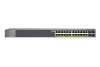
, GS728TP, and GS728TPP Gigabit Smart Switch Overview The NETGEAR GS752TP, GS728TP, and GS728TPP Gigabit Smart Switch provides 48 or 24 twisted-pair ports that support nonstop 10/100/1000M networks. The switch also has four built-in enhanced small form factor pluggable (SFP) GBIC slots that support - Netgear GS728TP | GS728TP/GS728TPP/GS752TP Hardware Installation Guide - Page 7
GS752TP, GS728TP, and GS728TPP Gigabit Smart Switch • IEEE 802.3z packet loss and frame drops. • Half-duplex backpressure control. • LEDs. Power LED, FAN Status LED, LED Mode LED, Max PoE LED, and LEDs for each port. • Internal open frame power supply. • Standard NETGEAR 7xx series chassis. • NETGEAR - Netgear GS728TP | GS728TP/GS728TPP/GS752TP Hardware Installation Guide - Page 8
the package contains the following: • GS752TP, GS728TP, or GS728TPP Gigabit Smart Switch • Rubber footpads for tabletop installation • Rack-mounting kit • Power cord • Installation guide • Smart Switch resource CD with NETGEAR Smart Control Center and user's manual If any item is missing or damaged - Netgear GS728TP | GS728TP/GS728TPP/GS752TP Hardware Installation Guide - Page 9
Physical Description 2 This chapter describes the GS752TP, GS728TP, and GS728TPP Gigabit Smart Switch hardware features. Topics include: • GS752TP Front Panel and Back Panel Configuration • GS728TP Front Panel and Back Panel Configuration • GS728TPP Front Panel and Back Panel Configuration • LED - Netgear GS728TP | GS728TP/GS728TPP/GS752TP Hardware Installation Guide - Page 10
with the link partner automatically. Figure 2 illustrates the front panel of the GS752TP Gigabit Smart Switch. Power, Fan, PoE Max, and LED Mode LEDs Link/ACT LEDs SFP ports Factory Defaults button Reset button Figure 2. Front panel The front panel contains the following: • 48 RJ-45 connectors - Netgear GS728TP | GS728TP/GS728TPP/GS752TP Hardware Installation Guide - Page 11
with the link partner automatically. Figure 4 illustrates the front panel of the GS728TP Gigabit Smart Switch. Power, Fan, PoE Max, and LED Mode LEDs Link/ACT LEDs SFP ports Factory Defaults button Reset button Figure 4. Front panel The front panel contains the following: • 24 RJ-45 connectors - Netgear GS728TP | GS728TP/GS728TPP/GS752TP Hardware Installation Guide - Page 12
back to the factory defaults. • Select button to change the working mode of the port LEDs with either PoE mode or Ethernet mode. • Port Status and Port Speed LEDs. • Power, Fan Status, Max PoE, and LED Mode LEDs. Figure 5 illustrates the NETGEAR GS728TPP Gigabit Smart Switch back panel. Figure - Netgear GS728TP | GS728TP/GS728TPP/GS752TP Hardware Installation Guide - Page 13
device back to the factory defaults. • Select button to change the working mode of the port LEDs with either PoE mode or Ethernet mode. • Port Status and Port Speed LEDs. • Power, Fan Status, Max PoE, and LED Mode LEDs. Figure 7 illustrates the NETGEAR GS728TPP Gigabit Smart Switch back panel. RPS - Netgear GS728TP | GS728TP/GS728TPP/GS752TP Hardware Installation Guide - Page 14
GS728TP, and GS728TPP Gigabit Smart Switch LED Designations Port LEDs The following table describes the RJ-45 and dedicated SFP port LED designations. LED Designation Link/ACT LED mode for copper ports 1-48 or 1-24 Link/ACT Mode port is transmitting or receiving packets at 1000 Mbps. • Solid - Netgear GS728TP | GS728TP/GS728TPP/GS752TP Hardware Installation Guide - Page 15
GS752TP, GS728TP, and GS728TPP Gigabit Smart Switch System LEDs The following table describes the system LED designations. LED Power Fan Max PoE LED LED Status . • Off. At least 7W of PoE power is available. • Solid green. The Port LED is in Ethernet mode. • Solid yellow. The Port LED is in PoE - Netgear GS728TP | GS728TP/GS728TPP/GS752TP Hardware Installation Guide - Page 16
GS728TP, and GS728TPP Gigabit Smart Switch Device Hardware Interfaces RJ-45 Ports RJ-45 ports are AutoSensing ports. When you insert a cable into an RJ-45 port, the switch automatically ascertains the maximum speed (10, 100, or 1000 Mbps) and duplex mode the port to a router, switch, or hub). • - Netgear GS728TP | GS728TP/GS728TPP/GS752TP Hardware Installation Guide - Page 17
-test (POST). Factory Defaults Button The Smart Switch has a Factory Defaults button on the front panel so that you can remove the current configuration and return the device to its factory settings. When you press the Factory Defaults button, all settings including the password, VLAN settings, and - Netgear GS728TP | GS728TP/GS728TPP/GS752TP Hardware Installation Guide - Page 18
. Desktop Switching The GS752TP, GS728TP, and GS728TPP Gigabit Smart Switch can be used as a desktop switch to build a small network that enables users to have 1000 Mbps access to a file server. With full-duplex mode enabled, the switch port connected to the server or computer can provide 2000 - Netgear GS728TP | GS728TP/GS728TPP/GS752TP Hardware Installation Guide - Page 19
GS752TP, GS728TP, and GS728TPP Gigabit Smart Switch Backbone Switching You can use the GS752TP, GS728TP, and GS728TPP Gigabit Smart Switch as a backbone switch in a small network that gives users high-speed access to servers and other network devices. Figure 9. Backbone switching 20 - Netgear GS728TP | GS728TP/GS728TPP/GS752TP Hardware Installation Guide - Page 20
4. Installation 4 This chapter describes the installation procedures for your GS752TP, GS728TP, and GS728TPP Gigabit Smart Switch. Switch installation involves the following steps: Step 1: Prepare the Site Step 2: Install the Switch Step 3: Check the Installation Step 4: Connect Devices to the - Netgear GS728TP | GS728TP/GS728TPP/GS752TP Hardware Installation Guide - Page 21
, such as a photocopy machine. Step 2: Install the Switch The GS752TP, GS728TP, and GS728TPP Gigabit Smart Switch can be used on a flat surface or mounted in a standard network equipment rack. Install the Switch on a Flat Surface The switch ships with four self-adhesive rubber footpads. Stick one - Netgear GS728TP | GS728TP/GS728TPP/GS752TP Hardware Installation Guide - Page 22
GS752TP, GS728TP, and GS728TPP Gigabit Smart Switch 3. Tighten the screws with a No. 1 Phillips screwdriver to secure each bracket. 4. Align the mounting holes in the brackets with the holes in the rack, and insert two pan-head screws with nylon washers through each bracket and into the - Netgear GS728TP | GS728TP/GS728TPP/GS752TP Hardware Installation Guide - Page 23
GS728TP, and GS728TPP Gigabit Smart Switch Step 4: Connect Devices to the Switch The following procedure describes how to connect computers to the switch's RJ-45 ports. The switch specifications limit the cable length between the switch and of the switch. Note: Contact your NETGEAR sales office to buy - Netgear GS728TP | GS728TP/GS728TPP/GS752TP Hardware Installation Guide - Page 24
the switch's front panel lights. If the Power LED does not light, check that the power cable is plugged in correctly and that the power source is good. If this does not resolve the problem, refer to Appendix A, Troubleshooting. Step 7: Apply RPS DC Power This step is applicable to the GS728TPP only - Netgear GS728TP | GS728TP/GS728TPP/GS752TP Hardware Installation Guide - Page 25
using a web browser or a program called Smart Control Center. For more information about managing the switch, see the software administration manual on the Smart Switch resource CD. Note: The switch is configured with a default IP address of 192.168.0.239 and a subnet mask of 255.255.255.0. 26 - Netgear GS728TP | GS728TP/GS728TPP/GS752TP Hardware Installation Guide - Page 26
A. Troubleshooting A This chapter provides information about troubleshooting the NETGEAR Smart Switch. Topics include the following: • Troubleshooting Chart • Additional Troubleshooting Suggestions 27 - Netgear GS728TP | GS728TP/GS728TPP/GS752TP Hardware Installation Guide - Page 27
GS752TP, GS728TP, and GS728TPP Gigabit Smart Switch Troubleshooting Chart The following table lists symptoms and causes of, and solutions to possible problems. Symptom Cause Solution Power LED is off. No power is received. Check the power cord connections and the connected device. Ensure that - Netgear GS728TP | GS728TP/GS728TPP/GS752TP Hardware Installation Guide - Page 28
, verify the integrity of the switch by resetting the switch. To reset the switch, remove the AC power from the switch and then reapply AC power. If the problem continues, contact NETGEAR technical support. Autonegotiation The RJ-45 ports negotiate the correct duplex mode, speed, and flow control if - Netgear GS728TP | GS728TP/GS728TPP/GS752TP Hardware Installation Guide - Page 29
B. Technical Specifications B Network Protocol and Standards Compatibility IEEE 802.3 10BASE-T IEEE , Windows XP, Windows 7, Microsoft Explorer 7.0 or later, Firefox 4 or later IEEE 802.1Q VLAN IEEE 802.3ad link aggregation IEEE 802.1D Spanning Tree Protocol IEEE 802.1w Rapid Spanning Tree Protocol - Netgear GS728TP | GS728TP/GS728TPP/GS752TP Hardware Installation Guide - Page 30
LEDs Per port: Link/Act Mode Per device: Power, Fan, PoE Max, LED Mode Performance Specifications Forwarding modes: Store-and-forward Bandwidth (per unit): 56 Gbps for GS728TP/GS728TPP, 104 Gbps for GS752TP Address database size: 8K Media Access Control (MAC) addresses per system PoE power budget - Netgear GS728TP | GS728TP/GS728TPP/GS752TP Hardware Installation Guide - Page 31
GS752TXS Smart Switch • GS728TPP: • Maximum 384W (AC) • Maximum 720W for DC mode or AC+DC mode when using external power supply RPS4000. Mean Time Between Failure (MTBF): • GS752TP: • 220447.0 hours (~25.2 years) at 25°C • 64873.4 hours (~7.4 years) at 55°C • GS728TP: • 345901.2 hours (~40.0 years) - Netgear GS728TP | GS728TP/GS728TPP/GS752TP Hardware Installation Guide - Page 32
GS752TXS Smart Switch • GS752TP: 5.10 kg • GS728TPP: 4.36 kg • GS728TP: 3.73 kg Environmental Specifications Operating temperature: 0-50°C (32-104°F) Operating humidity: 10% to 95% maximum relative humidity, noncondensing Storage temperature: -20 to 70°C (-4 to 158°F) Storage humidity: 5% to 95% - Netgear GS728TP | GS728TP/GS728TPP/GS752TP Hardware Installation Guide - Page 33
's firmware limits operation to only the channels allowed in a particular Region or Country. Therefore, all options described in this user's guide may Of Conformity We, NETGEAR, Inc., 350 East Plumeria Drive, San Jose, CA 95134, declare under our sole responsibility that the switch complies with Part - Netgear GS728TP | GS728TP/GS728TPP/GS752TP Hardware Installation Guide - Page 34
to the product, unless expressly approved by NETGEAR, Inc., could void the user's right to operate the equipment. Canadian Department of Communications Radio Interference Regulations This digital apparatus, GS752TP, GS728TP, and GS728TPP Gigabit Smart Switch, does not exceed the Class B limits for - Netgear GS728TP | GS728TP/GS728TPP/GS752TP Hardware Installation Guide - Page 35
7 C Category 5 unshielded twisted-pair 6 checking the installation 23 Class of Service 6 compliance 35 connect devices to the switch 24 crossover cables 16 D device hardware interfaces 16 duplex mode 16 F factory defaults 10, 12, 13 Factory Defaults button 10, 12, 13, 17 flat surface 22 full-duplex - Netgear GS728TP | GS728TP/GS728TPP/GS752TP Hardware Installation Guide - Page 36
GS752TP, GS728TP, and GS728TPP Gigabit Smart Switches Hardware Installation Guide temperature 22 trademarks 2 traffic control 6 troubleshooting chart 28 U user intervention 16 user's manual 8 UTP 24 V ventilation 22 VLAN 6 W web-based graphical user interface 6 38 | Index
-
 1
1 -
 2
2 -
 3
3 -
 4
4 -
 5
5 -
 6
6 -
 7
7 -
8
-
9
-
10
-
11
-
12
-
13
-
14
-
15
-
16
-
17
-
18
-
19
-
20
-
21
-
22
-
23
-
24
-
25
-
26
-
27
-
28
-
29
-
30
-
31
-
32
-
33
-
34
-
35
-
36
 |
 |

350 East Plumeria Drive
San Jose, CA 95134
USA
December 2012
202-11136-01
v1.0
ProSafe® GS752TP,
GS728TP, and GS728TPP
Gigabit Smart Switches
Hardware Installation Guide