Netgear GS728TXS GS728TXS/GS752TXS Hardware Installation Guide
Netgear GS728TXS Manual
 |
View all Netgear GS728TXS manuals
Add to My Manuals
Save this manual to your list of manuals |
Netgear GS728TXS manual content summary:
- Netgear GS728TXS | GS728TXS/GS752TXS Hardware Installation Guide - Page 1
GS728TXS/GS752TXS Smart Switch Hardware Installation Guide 350 East Plumeria Drive San Jose, CA 95134 USA March 2013 202-11201-01 v1.1 - Netgear GS728TXS | GS728TXS/GS752TXS Hardware Installation Guide - Page 2
GS728TXS/GS752TXS Smart Switch Support Thank you for selecting NETGEAR products. After installing your device, locate the serial number on the label of your product and use it to register your product at https://my.netgear.com. You must register your product before you can use NETGEAR telephone - Netgear GS728TXS | GS728TXS/GS752TXS Hardware Installation Guide - Page 3
Package Contents 8 Chapter 2 Physical Description GS728TXS Description 11 GS728TXS Front Panel and Back Panel Configuration Manage the Switch Using a Web Browser or the Smart Control Center Utility 26 Appendix A Troubleshooting Troubleshooting Chart 29 Additional Troubleshooting Suggestions 29 - Netgear GS728TXS | GS728TXS/GS752TXS Hardware Installation Guide - Page 4
30 Appendix B Technical Specifications Network Protocol and Standards Compatibility 32 Management 32 Interface 33 GS728TXS Smart Switch 33 GS752TXS Smart Switch 33 LEDs 33 Performance Specifications 33 Power Supply 33 Physical Specifications 34 Environmental Specifications 34 - Netgear GS728TXS | GS728TXS/GS752TXS Hardware Installation Guide - Page 5
4 SFP+ ports that support 1000M and 10G optical modules or up to two stacking modules. To simplify installation, the switch is shipped ready for use out of the box. This installation guide describes how to install and power on the smart switch. The information in this manual is intended for readers - Netgear GS728TXS | GS728TXS/GS752TXS Hardware Installation Guide - Page 6
GS728TXS/GS752TXS Smart Switch Overview The NETGEAR GS728TXS/GS752TXS Smart Switch provides either 24 (GS728TXS) or 48 (GS752TXS) twisted-pair ports that support nonstop 10/100/1000M networks. The switch also has four built-in enhanced small form factor pluggable (SFP+) GBIC slots that support 1000M - Netgear GS728TXS | GS728TXS/GS752TXS Hardware Installation Guide - Page 7
GS728TXS/GS752TXS Smart Switch . • Standard NETGEAR 7xx series chassis (1U high). • NETGEAR Green product series called a stack slave member. In particular, firmware can be downloaded from the stack master to if the stack master fails. In the default configuration, the master and backup master are - Netgear GS728TXS | GS728TXS/GS752TXS Hardware Installation Guide - Page 8
GS728TXS and GS752TXS switches. Package Contents The following figure shows the package contents of the smart switch. (The figure shows the GS752TXS Smart Switch; however, the GS728TXS Smart Switch 52F SFP + Reset Factory Defaults Green=10G Link Yellow=1G Blink=ACT Figure 1. Package contents 8 - Netgear GS728TXS | GS728TXS/GS752TXS Hardware Installation Guide - Page 9
that the package contains the following: • GS728TXS/GS752TXS Smart Switch • Rubber footpads for tabletop installation • Rack-mounting kits • Power cord • Installation guide • Smart switch resource CD with NETGEAR Smart Control Center and user's manual If any item is missing or damaged, contact - Netgear GS728TXS | GS728TXS/GS752TXS Hardware Installation Guide - Page 10
2. Physical Description 2 This chapter describes the GS728TXS/GS752TXS Smart Switch hardware features. Topics include: • GS728TXS Description • GS752TXS Description 10 - Netgear GS728TXS | GS728TXS/GS752TXS Hardware Installation Guide - Page 11
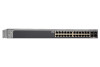
panel of the smart switch. Power, Fan, and Stack Master LEDs Stack ID LED Power Fan Stack Master ID Reset Factory Defaults Link/Speed/ACT 26F GS728TXS 27F 28F SFP + Green=10G Link Yellow=1G Blink=ACT Factory Defaults button 10/100/1000 Ethernet ports Reset button Figure 2. GS728TXS - Netgear GS728TXS | GS728TXS/GS752TXS Hardware Installation Guide - Page 12
GS728TXS/GS752TXS Smart Switch Kensington Lock™ slot Figure 3. GS728TXS back panel The back panel contains a power connector. Power connector LED Designations This section describes the LEDs on the smart switch. Port LEDs The following table describes the RJ-45 and dedicated SFP port LED - Netgear GS728TXS | GS728TXS/GS752TXS Hardware Installation Guide - Page 13
GS728TXS/GS752TXS Smart Switch System LEDs The following table describes the system LED designations. an 8-pin RJ-45 plug. To simplify the procedure for attaching devices, all RJ-45 ports support Auto Uplink. This technology allows attaching devices to the RJ-45 ports with either straight-through - Netgear GS728TXS | GS728TXS/GS752TXS Hardware Installation Guide - Page 14
-test (POST). Factory Defaults Button The smart switch has a Factory Defaults button on the front panel so that you can remove the current configuration and return the device to its factory settings. When you enable the Factory Defaults button, all settings including the password, VLAN settings, and - Netgear GS728TXS | GS728TXS/GS752TXS Hardware Installation Guide - Page 15
GS728TXS/GS752TXS Smart Switch Power, Fan, and Stack Master LEDs Stack ID LED Link/Speed/ACT LEDs 1000M/10G to the factory defaults. • Link, Speed, and ACT LEDs for each port. • Power, Fan, Stack Master, and Stack ID LEDs. The following figure illustrates the smart switch back panel. Kensington - Netgear GS728TXS | GS728TXS/GS752TXS Hardware Installation Guide - Page 16
GS728TXS/GS752TXS Smart Switch Port LEDs The following table describes the RJ-45 and dedicated SFP port LED designations. Each RJ-45 port has one LED. Each SFP port - Netgear GS728TXS | GS728TXS/GS752TXS Hardware Installation Guide - Page 17
-test (POST). Factory Defaults Button The smart switch has a Factory Defaults button on the front panel so that you can remove the current configuration and return the device to its factory settings. When you press the Factory Defaults button, all settings including the password, VLAN settings, and - Netgear GS728TXS | GS728TXS/GS752TXS Hardware Installation Guide - Page 18
GS728TXS/GS752TXS Smart Switch is designed to provide flexibility in configuring your network connections. It can be used as your only network traffic-distribution device or with 10 Mbps, 100 Mbps, 1000 Mbps, and 10-Gbps hubs and switches. Topics include: • Desktop Switching • Backbone Switching - Netgear GS728TXS | GS728TXS/GS752TXS Hardware Installation Guide - Page 19
figure shows the GS752TXS Smart Switch; however, the GS728TXS Smart Switch can also be used for desktop switching.) Power Fan Stack Master Defaults Green=10G Link Yellow=1G Blink=ACT ` ` ` ` Figure 6. Desktop switching Backbone Switching You can use the smart switch as a backbone switch - Netgear GS728TXS | GS728TXS/GS752TXS Hardware Installation Guide - Page 20
GS728TXS/GS752TXS Smart Switch GS728TXS/GS752TXS Power Fan Stack Master ID Link/Act Mode - 1 2 3 4 5 6 7 8 9 10 11 46 47 48 49F 50F GS752TXS 51F 52F SFP + Reset Factory Defaults Green=10G Link Yellow=1G Blink=ACT Model GS108T Model FS728TP ` ` ` ` ` Figure 7. Backbone - Netgear GS728TXS | GS728TXS/GS752TXS Hardware Installation Guide - Page 21
Installation 4 This chapter describes the installation procedures for your GS728TXS/GS752TXS Smart Switch. Switch installation involves the steps described in the following sections: Step 1: Prepare the Site Step 2: Install the Switch Step 3: Check the Installation Step 4: Connect Devices to the - Netgear GS728TXS | GS728TXS/GS752TXS Hardware Installation Guide - Page 22
GS728TXS/GS752TXS Smart Switch Step 1: Prepare the Site Before you install the switch, ensure that the operating environment meets the site requirements in the following table. Table 5. Site requirements Characteristics Requirements Mounting • Desktop installations. Provide a flat table or - Netgear GS728TXS | GS728TXS/GS752TXS Hardware Installation Guide - Page 23
and into the rack. 5. Tighten the screws with a No. 2 Phillips screwdriver to secure mounting brackets to the rack. Note: The figure shows the GS752TXS Smart Switch; however, the GS728TXS Smart Switch is installed in the same manner. Step 3: Check the Installation Before applying power to the - Netgear GS728TXS | GS728TXS/GS752TXS Hardware Installation Guide - Page 24
Defaults Green=10G Link Yellow=1G Blink=ACT ` ` Figure 8. Connecting devices to the switch Note: Ethernet specifications limit the cable length between the switch the switch. Note: Contact your NETGEAR sales Smart Switch; however, the GS728TXS Smart Switch is connected in the same manner.) 24 - Netgear GS728TXS | GS728TXS/GS752TXS Hardware Installation Guide - Page 25
45 46 47 48 49F 50F GS752TXS 51F 52F SFP + Reset Factory Defaults Green=10G Link Yellow=1G Blink=ACT Figure 9. Installing an SFP transceiver supports two stacking topologies: ring topology or chain topology. (The figure shows the GS752TXS Smart Switch; however, the GS728TXS Smart Switch is - Netgear GS728TXS | GS728TXS/GS752TXS Hardware Installation Guide - Page 26
and that the power source is good. If this does not resolve the problem, see Appendix A, Troubleshooting. Step 8: Manage the Switch Using a Web Browser or the Smart Control Center Utility The smart switch contains software for viewing, changing, and monitoring the way it works. This management - Netgear GS728TXS | GS728TXS/GS752TXS Hardware Installation Guide - Page 27
GS728TXS/GS752TXS Smart Switch Note: The switch is configured with a default IP address of 192.168.0.239 and a subnet mask of 255.255.255.0. 27 - Netgear GS728TXS | GS728TXS/GS752TXS Hardware Installation Guide - Page 28
A. Troubleshooting A This appendix provides information about troubleshooting the NETGEAR smart switch. Topics include the following: • Troubleshooting Chart • Additional Troubleshooting Suggestions 28 - Netgear GS728TXS | GS728TXS/GS752TXS Hardware Installation Guide - Page 29
ports. See the GG728TXS/GS752TXS Smart Switch Software Administration Manual for information about using the web interface. Additional Troubleshooting Suggestions If the suggestions in the troubleshooting chart do not resolve the problem, see the troubleshooting suggestions in this section. 29 - Netgear GS728TXS | GS728TXS/GS752TXS Hardware Installation Guide - Page 30
If necessary, verify the integrity of the switch by resetting the switch. To reset the switch, remove the AC power from the switch and then reapply AC power. If the problem continues, contact NETGEAR technical support. In North America, call 1-888-NETGEAR. If you are outside of North America - Netgear GS728TXS | GS728TXS/GS752TXS Hardware Installation Guide - Page 31
B. Technical Specifications B This appendix lists the specifications for the NETGEAR smart switch. Topics include the following: • Network Protocol and Standards Compatibility • Management • Interface • LEDs • Performance Specifications • Power Supply • Physical Specifications • Environmental - Netgear GS728TXS | GS728TXS/GS752TXS Hardware Installation Guide - Page 32
GS728TXS/GS752TXS Smart Switch Network Protocol and Standards Compatibility • IEEE 802.3 10BASE-T • IGMP snooping v1/v2/v3 • IEEE 802.1p Class of Service (CoS) • SNTP (Simple Network Time Protocol) 3 servers; disabled by default. • Jumbo frame support (9K) • IPv6 management, multicast, and QoS • - Netgear GS728TXS | GS728TXS/GS752TXS Hardware Installation Guide - Page 33
section lists the interfaces specifications for the GS728TXS Smart Switch and the GS752TXS Smart Switch. GS728TXS Smart Switch • 24 RJ-45 connectors for 10BASE-T, 100BASE-TX, and 1000BASE-T (Auto Uplink on all ports). • Four 10 Gbps SFP+ slots (ports 25-29) to support 10-Gbps optical module and 1G - Netgear GS728TXS | GS728TXS/GS752TXS Hardware Installation Guide - Page 34
Specifications • Dimensions (H x W x D): 43 mm x 440 mm x 257 mm (1.7 in. x 17.3 in. x10.1 in.) • Weight: - GS728TXS Smart Switch: 3.55 kg (7.83 lbs) - GS752TXS Smart Switch: 4.50 kg (9.92 lbs) Environmental Specifications • Operating temperature: 0°C to 50°C (32°F to 104°F) • Operating humidity: 10 - Netgear GS728TXS | GS728TXS/GS752TXS Hardware Installation Guide - Page 35
of Compliance NETGEAR Wired Products 's firmware limits operation to only the channels allowed in a particular Region or Country. Therefore, all options described in this user's guide may to User This product does not contain any user serviceable components and is to be used with approved antennas - Netgear GS728TXS | GS728TXS/GS752TXS Hardware Installation Guide - Page 36
We, NETGEAR, Inc., 350 East Plumeria Drive, San Jose, CA 95134, declare under our sole responsibility that the GS728TXS/GS752TXS Smart Switch complies may cause undesired operation. FCC Radio Frequency Interference Warnings & Instructions This equipment has been tested and found to comply with the
-
 1
1 -
 2
2 -
 3
3 -
 4
4 -
 5
5 -
 6
6 -
 7
7 -
8
-
9
-
10
-
11
-
12
-
13
-
14
-
15
-
16
-
17
-
18
-
19
-
20
-
21
-
22
-
23
-
24
-
25
-
26
-
27
-
28
-
29
-
30
-
31
-
32
-
33
-
34
-
35
-
36
 |
 |

350 East Plumeria Drive
San Jose, CA 95134
USA
March 2013
202-11201-01
v1.1
GS728TXS/GS752TXS
Smart Switch
Hardware Installation Guide