Netgear M4300-28G Hardware Installation Guide
Netgear M4300-28G Manual
 |
View all Netgear M4300-28G manuals
Add to My Manuals
Save this manual to your list of manuals |
Netgear M4300-28G manual content summary:
- Netgear M4300-28G | Hardware Installation Guide - Page 1
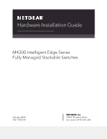
Hardware Installation Guide M4300 Intelligent Edge Series Fully Managed Stackable Switches January 2020 202-12073-01 NETGEAR, Inc. 350 E. Plumeria Drive San Jose, CA 95134, USA - Netgear M4300-28G | Hardware Installation Guide - Page 2
Support Thank you for purchasing this NETGEAR product. You can visit https://www.netgear.com/support/ to register your product, get help, access the latest downloads and user manuals -48XF. Made minor corrections to existing sections. Published the guide in a new format. 202-11606-05 May 2018 Added - Netgear M4300-28G | Hardware Installation Guide - Page 3
M4300 Intelligent Edge Series Fully Managed Stackable Switches (Continued) Publication Part Publish Date Number Comments 202-11606-02 December 2015 Added information to the Safety Instructions and Warnings section. 202-11606-01 December 2015 First publication. 3 - Netgear M4300-28G | Hardware Installation Guide - Page 4
Contents Chapter 1 Introduction Overview 7 Hardware features 8 About stacking 10 Safety instructions and warnings 11 Chapter 2 Hardware Overview Hardware descriptions, M4300 series full 10G models 15 Front panel, M4300 series full 10G models 15 Back panel, M4300 - Netgear M4300-28G | Hardware Installation Guide - Page 5
8: Check the installation 60 Step 9: Apply AC power and check the LEDs 61 Optional Step 10: Connect a console to the switch 62 Chapter 4 Maintenance and Troubleshooting Replace a power supply unit 65 Replace a half-width switch in a rack 66 - Netgear M4300-28G | Hardware Installation Guide - Page 6
the following sections: • Overview • Hardware features • About stacking • Safety instructions and warnings Note: For more information about the topics that are covered in this manual, visit the support website at netgear.com/support/. Note: For technical specifications, see the data sheet at - Netgear M4300-28G | Hardware Installation Guide - Page 7
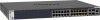
, and 28-port and 52-port 1G/10G models that can also support PoE+. All ports on the 10G models are stackable. On the 1G models with 10G uplinks, the two or four 10G ports are stackable. This installation guide is for the following models: • Full 10G models: - M4300-16X. Full 10G - Netgear M4300-28G | Hardware Installation Guide - Page 8
10GBASE-X SFP+ ports - Twenty-four or forty-eight 1000BASE-T PoE+ autosensing ports, two dedicated 10GBASE-T ports, and two dedicated 10GBASE-X SFP+ ports Introduction 8 Hardware Installation Guide - Netgear M4300-28G | Hardware Installation Guide - Page 9
ports and two 10G RJ45/SFP+ combo ports • Support from 128G to 960G switching fabric (all ports line- dual PSU bay models, the second PSU can support 1+1 redundancy. • Support for stacking on any 10G port. • Half-width ports. • Auto Uplink™ technology is supported on all ports. • Automatic address - Netgear M4300-28G | Hardware Installation Guide - Page 10
Per-port status LEDs and system status LEDs. • Nonstop Forwarding Failover (NSF) support for the master in a stack. • NETGEAR green power-saving features: - Energy efficiency mode that fully conforms to the IEEE802 which to control and manage the stack. Introduction 10 Hardware Installation Guide - Netgear M4300-28G | Hardware Installation Guide - Page 11
For information about how to configure stacking through the software, see the software administration guide and user manual, which you can download by visiting netgear.com/support/download/. Safety instructions and warnings Use the following safety guidelines to ensure your own personal safety and - Netgear M4300-28G | Hardware Installation Guide - Page 12
system components, and never operate the product in a wet environment. If the system gets wet, see the appropriate section in your troubleshooting guide, or contact your trained service provider. • Do not push any objects into the openings of your system. Doing so can cause fire or electric shock by - Netgear M4300-28G | Hardware Installation Guide - Page 13
device uses a power adapter: - If you were not provided with a power adapter, contact your local NETGEAR reseller. - The power adapter must be rated for the product and for the voltage and current marked on follow your local and national wiring rules. Introduction 13 Hardware Installation Guide - Netgear M4300-28G | Hardware Installation Guide - Page 14
2 Hardware Overview This chapter describes the switch hardware features. The chapter includes the following sections: • Hardware descriptions, M4300 series full 10G models • Hardware descriptions, M4300 series 1G models with 10G uplinks • Hardware descriptions, M4300 series full 10G models with RJ45 - Netgear M4300-28G | Hardware Installation Guide - Page 15
1 2 3 4 5 Description Power, PoE Max, and Fan LEDs Stack ID LED USB port RJ-45 RS232 console port Stack Master LED Hardware Overview 15 Hardware Installation Guide - Netgear M4300-28G | Hardware Installation Guide - Page 16
console port OOB port with port LEDs 10GBASE-X SFP+ ports, each with a port LED 10GBASE-T ports, each with a port LED Hardware Overview 16 Hardware Installation Guide - Netgear M4300-28G | Hardware Installation Guide - Page 17
-24X24F The following figure illustrates the front panel of full-width model M4300-24X24F. Figure 4. Front panel model M4300-24X24F Hardware Overview 17 Hardware Installation Guide - Netgear M4300-28G | Hardware Installation Guide - Page 18
and Stack ID system LEDs (see LEDs, M4300 series full 10G models on page 21) . Because model M4300-24X24F can support two PSUs, the front panel provides both a Power 1 LED and Power 2 LED. • Recessed Reset button. • One mini 10G models on page 21). Hardware Overview 18 Hardware Installation Guide - Netgear M4300-28G | Hardware Installation Guide - Page 19
back panel of half-width model M4300-8X8F. Figure 6. Back panel model M4300-8X8F Number 1 Description PSU with AC connector Hardware Overview 19 Hardware Installation Guide - Netgear M4300-28G | Hardware Installation Guide - Page 20
-24X24F The following figure illustrates the back panel of full-width model M4300-24X24F. Figure 8. Back panel model M4300-24X24F Hardware Overview 20 Hardware Installation Guide - Netgear M4300-28G | Hardware Installation Guide - Page 21
failed or another failure occurred. Off. Power is not supplied to the switch. Note: Because model M4300-24X24F can support two PSUs, the front panel provides both a Power 1 LED and Power 2 LED. PoE model (M4300-16X) is not a member of a stack. Hardware Overview 21 Hardware Installation Guide - Netgear M4300-28G | Hardware Installation Guide - Page 22
100 Mbps link. Blinking yellow. The copper port is transmitting or receiving packets at 5 Gbps, 2.5 Gbps, 1 Gbps, or 100 Mbps. Hardware Overview 22 Hardware Installation Guide - Netgear M4300-28G | Hardware Installation Guide - Page 23
1 2 3 4 Hardware Overview Description Power 1, Power 2, and Fan LEDs Stack ID LED 10GBASE-T ports, each with a port LED OOB port with port LEDs 23 Hardware Installation Guide - Netgear M4300-28G | Hardware Installation Guide - Page 24
10GBASE-X SFP+ ports, each with a port LED USB port Model M4300-28G-POE+ Model M4300-28G-POE+ supports PoE+ on ports 1 through 24. The following figure illustrates the front panel of full-width model M4300-28G-POE , each with a port LED USB port Hardware Overview 24 Hardware Installation Guide - Netgear M4300-28G | Hardware Installation Guide - Page 25
port 1000BASE-T ports, each with a port LED 10GBASE-X SFP+ ports, each with a port LED USB port Model M4300-52G-POE+ Model M4300-52G-POE+ supports PoE+ on ports 1 through 48. The following figure illustrates the front panel of full-width model M4300-52G-POE+. Figure 12. Front panel model M4300- - Netgear M4300-28G | Hardware Installation Guide - Page 26
numbers 25 and 26. - On model M4300-52G and model M4300-52G-POE+, these are port numbers 49 and 50. Hardware Overview 26 Hardware Installation Guide - Netgear M4300-28G | Hardware Installation Guide - Page 27
APS550W PSU or APS1000W PSU is installed, depending on the product ordered. • Second modular bay for an optional second PSU. Hardware Overview 27 Hardware Installation Guide - Netgear M4300-28G | Hardware Installation Guide - Page 28
unit (PSU) or APS1000W PSU is installed, depending on the product ordered. • Second modular bay for an optional second PSU. Hardware Overview 28 Hardware Installation Guide - Netgear M4300-28G | Hardware Installation Guide - Page 29
the copper port. Solid green. The copper port established a link. Blinking green. The copper port is transmitting or receiving packets. Hardware Overview 29 Hardware Installation Guide - Netgear M4300-28G | Hardware Installation Guide - Page 30
port established a link. Blinking green. The port is transmitting or receiving packets. Off. No link is established on the port. Hardware Overview 30 Hardware Installation Guide - Netgear M4300-28G | Hardware Installation Guide - Page 31
-width model M4300-24X. Figure 15. Front panel model M4300-24X Number 1 2 Figure Power and Fan LEDs Stack ID LED Hardware Overview 31 Hardware Installation Guide - Netgear M4300-28G | Hardware Installation Guide - Page 32
ports (23 and 24), each with a port LED (the corresponding 10GBASE-T RJ-45 combo ports are on the back panel) Hardware Overview 32 Hardware Installation Guide - Netgear M4300-28G | Hardware Installation Guide - Page 33
The following figure illustrates the front panel of full-width model M4300-48XF. Figure 18. Front panel model M4300-48XF Hardware Overview 33 Hardware Installation Guide - Netgear M4300-28G | Hardware Installation Guide - Page 34
M4300X series full 10G models with RJ45/SFP+ combo ports on page 38). Because models M4300-48X and M4300-48XF can support two PSUs, the front panel provides both a Power 1 LED and Power 2 LED. • Recessed Reset button. • + combo ports on page 38). Hardware Overview 34 Hardware Installation Guide - Netgear M4300-28G | Hardware Installation Guide - Page 35
ports on page 38). • Four combo SFP+ ports. • Modular bay in which an APS250W power supply unit (PSU) is installed. Hardware Overview 35 Hardware Installation Guide - Netgear M4300-28G | Hardware Installation Guide - Page 36
page 38). • Two combo 10GBASE-T RJ-45 ports. • Modular bay in which an APS250W power supply unit (PSU) is installed. Hardware Overview 36 Hardware Installation Guide - Netgear M4300-28G | Hardware Installation Guide - Page 37
series full 10G models with RJ45/SFP+ combo ports on page 38). • Modular bay PSU 2 for an optional second PSU. Hardware Overview 37 Hardware Installation Guide - Netgear M4300-28G | Hardware Installation Guide - Page 38
the back panel. • For model M4300-24XF, the LEDs for the 10GBASE-T RJ45 combo ports are on the back panel. Hardware Overview 38 Hardware Installation Guide - Netgear M4300-28G | Hardware Installation Guide - Page 39
failure occurred. Off. Power is not supplied to the switch. Note: Because models M4300-48X and M4300-48XF can support two PSUs, the front panel provides both a Power 1 LED and Power 2 LED. Fan LED Solid green. + combo ports are on the back panel. Hardware Overview 39 Hardware Installation Guide - Netgear M4300-28G | Hardware Installation Guide - Page 40
and the speeds that these cables can support, up to 100 meters (328 feet RJ-45 ports All copper RJ-45 ports support autosensing. When you insert a cable into duplex) of the attached device. All ports support a Category 5 (Cat 5) unshielded twisted-pair all RJ-45 ports support Auto Uplink technology. - Netgear M4300-28G | Hardware Installation Guide - Page 41
modules and direct attach cables (DACs), all of which are sold separately. The switch supports the following NETGEAR SFP and SFP+ transceiver modules and cables: • Short-reach fiber transceiver modules: - 10GBASE-LR Lite, SFP+ single mode LC GBIC Hardware Overview 41 Hardware Installation Guide - Netgear M4300-28G | Hardware Installation Guide - Page 42
The NTFS file type is not supported. Because of hardware limitations, the write speed to and read speed from a USB device is about 1 Mbps. Note: In a stack, only the switch that functions as the master can detect and manage an attached USB device. Hardware Overview 42 Hardware Installation Guide - Netgear M4300-28G | Hardware Installation Guide - Page 43
computer. To download the VT100 terminal emulation software and Windows USB driver, visit https://www.netgear.com/support/, enter your model number in the search box, and click the Downloads button on the Reset button for about three seconds. Hardware Overview 43 Hardware Installation Guide - Netgear M4300-28G | Hardware Installation Guide - Page 44
the product ordered. For models that can support two PSUs, you can order a second PSU as an option. Table 5. Supported PSUs Switch Model M4300-16X M4300-8X8F M4300 APS550W + 1x APS1000W (see Note) N+1 redundancy is supported for this model 1x APS550W 2x APS550W 1x APS1000W 2x APS1000W 1x APS550W - Netgear M4300-28G | Hardware Installation Guide - Page 45
48X M4300-48XF Possible PSU Configurations 1x APS250W 2x APS250W 1x APS250W 2x APS250W Power Redundancy RPS Support Note: For models M4300-28G-POE+ and M4300-52G-POE+, the switch automatically selects the APS1000W 591W 220 VAC input 720W 860W Hardware Overview 45 Hardware Installation Guide - Netgear M4300-28G | Hardware Installation Guide - Page 46
M4300-28G-POE+ M4300-52G-POE+ PoE Power Budget PoE Power Budget 630W 591W 720W 860W 720W 1,010W 720W 1,440W Hardware Overview 46 Hardware Installation Guide - Netgear M4300-28G | Hardware Installation Guide - Page 47
3 Installation This chapter describes the installation procedures for the switch. Switch installation involves the steps described in the following sections: • Step 1: Prepare the site • Step 2: Protect against electrostatic discharge • Step 3: Unpack the switch • Step 4: Install the switch • - Netgear M4300-28G | Hardware Installation Guide - Page 48
the electronic components, such as the microprocessor. You can do so by periodically touching an unpainted metal surface on the switch. Installation 48 Hardware Installation Guide - Netgear M4300-28G | Hardware Installation Guide - Page 49
full-width models (M4300-24X24F, M4300-28G, M4300-28G-POE+, M4300-52G-POE+, M4300-48X, and M4300-48XF) are the same. Installation 49 Hardware Installation Guide - Netgear M4300-28G | Hardware Installation Guide - Page 50
present before installing the switch. If any item is missing or damaged, contact your local NETGEAR reseller for replacement. To check the package contents: 1. Place the container on a • Rubber footpads for tabletop installation. • Quick installation guide. Installation 50 Hardware Installation - Netgear M4300-28G | Hardware Installation Guide - Page 51
through each bracket and into the rack. 5. Tighten the screws with a No. 2 Phillips screwdriver to secure mounting brackets to the rack. Installation 51 Hardware Installation Guide - Netgear M4300-28G | Hardware Installation Guide - Page 52
figures in the following procedure shows model M4300-24X. However, you install the other half-width models in the same manner. Installation 52 Hardware Installation Guide - Netgear M4300-28G | Hardware Installation Guide - Page 53
through each bracket and into the rack. 5. Tighten the screws with a No. 2 Phillips screwdriver to secure mounting brackets to the rack. Installation 53 Hardware Installation Guide - Netgear M4300-28G | Hardware Installation Guide - Page 54
other side. b. Tighten the screws with a No. 2 Phillips screwdriver to secure each middle mount to the right side of the switch. Installation 54 Hardware Installation Guide - Netgear M4300-28G | Hardware Installation Guide - Page 55
-mount kit through the holes in each middle mount. 5. Tighten the screws with a No. 1 Phillips screwdriver to secure each middle mount. Installation 55 Hardware Installation Guide - Netgear M4300-28G | Hardware Installation Guide - Page 56
+ ports. For information about supported modules, see 10GBASE-X, 1000BASE-X, and 1000BASE-T transceiver modules and cables for SFP+ ports on page 41. Note: Contact your NETGEAR sales office to purchase these modules M4300-12X12F, and model M4300-24X24F. Installation 56 Hardware Installation Guide - Netgear M4300-28G | Hardware Installation Guide - Page 57
the transceiver into the SFP+ port. 2. Press firmly on the flange of the module to seat it securely into the connector. Installation 57 Hardware Installation Guide - Netgear M4300-28G | Hardware Installation Guide - Page 58
models with RJ45/SFP+ combo ports in the same manner. Optional Step 6: Install a power supply unit The supported power supply unit (PSU) or PSUs depend on the switch model. For more information, see Power supply units on bay is the one on the right. Installation 58 Hardware Installation Guide - Netgear M4300-28G | Hardware Installation Guide - Page 59
model M4300-52G-POE+ This procedure is optional for model M4300-52G-POE+ only, which can support an optional RPS5412 external redundant power supply (RPS). That is, model M4300-52G-POE+ can support two internal power supply units (PSUs) and an external RPS. Installation 59 Hardware Installation - Netgear M4300-28G | Hardware Installation Guide - Page 60
make sure that cables are not damaged or creating a safety hazard. 4. Make sure that all equipment is mounted properly and securely. Installation 60 Hardware Installation Guide - Netgear M4300-28G | Hardware Installation Guide - Page 61
does not light, check to see that the power cord is plugged in correctly and that the power source is good. Installation 61 Hardware Installation Guide - Netgear M4300-28G | Hardware Installation Guide - Page 62
attach a computer or workstation, configure the terminal emulation program to use the following settings: • Baud rate. 115,200 bps • Data bits. 8 Installation 62 Hardware Installation Guide - Netgear M4300-28G | Hardware Installation Guide - Page 63
which you can download by visiting netgear.com/support/download/. For information about configuring the switch through its local browser interface, see the software administration guide and the user manual, which you can download by visiting netgear.com/support/download/. Installation 63 Hardware - Netgear M4300-28G | Hardware Installation Guide - Page 64
4 Maintenance and Troubleshooting This chapter provides information about maintaining and troubleshooting the switch. The chapter includes the following sections: • Replace a power supply unit • Replace a half-width switch in a rack • Troubleshooting chart • Additional troubleshooting suggestions 64 - Netgear M4300-28G | Hardware Installation Guide - Page 65
extraction handle. 3. Insert the other PSU into the power module bay, and gently push the PSU into the bay until the latch locks. Maintenance and Troubleshooting 65 Hardware Installation Guide - Netgear M4300-28G | Hardware Installation Guide - Page 66
add a support beneath the half-width switches when removing or installing a half-width switch. The support keeps the switches level while the mounting screws are loosened to avoid damage to both the switch and the middle mount screws. Maintenance and Troubleshooting 66 Hardware Installation Guide - Netgear M4300-28G | Hardware Installation Guide - Page 67
switch you want to replace. 2. Insert an item under the two half-width switches that can support the switches and keep them level during removal and installation. 3. Loosen the screws with a No. power and check the LEDs on page 61). Maintenance and Troubleshooting 67 Hardware Installation Guide - Netgear M4300-28G | Hardware Installation Guide - Page 68
chart The following table lists symptoms, causes, and solutions for possible problems. Table 9. Troubleshooting chart Symptom Cause Solution A Power LED is off. The switch is unit, with combo links used as the stacking ports. Maintenance and Troubleshooting 68 Hardware Installation Guide - Netgear M4300-28G | Hardware Installation Guide - Page 69
the AC power. If the problem continues, contact NETGEAR Technical Support. For more information, visit the support website at support.netgear.com. • Autonegotiation. The RJ control if the attached device supports autonegotiation. Maintenance and Troubleshooting 69 Hardware Installation Guide
-
 1
1 -
 2
2 -
 3
3 -
 4
4 -
 5
5 -
 6
6 -
 7
7 -
8
-
9
-
10
-
11
-
12
-
13
-
14
-
15
-
16
-
17
-
18
-
19
-
20
-
21
-
22
-
23
-
24
-
25
-
26
-
27
-
28
-
29
-
30
-
31
-
32
-
33
-
34
-
35
-
36
-
37
-
38
-
39
-
40
-
41
-
42
-
43
-
44
-
45
-
46
-
47
-
48
-
49
-
50
-
51
-
52
-
53
-
54
-
55
-
56
-
57
-
58
-
59
-
60
-
61
-
62
-
63
-
64
-
65
-
66
-
67
-
68
-
69
 |
 |

Hardware Installation Guide
M4300 Intelligent Edge Series
Fully Managed Stackable Switches
NETGEAR, Inc.
350 E. Plumeria Drive
January 2020
San Jose, CA 95134, USA
202-12073-01