Netgear MS108UP Installation Guide
Netgear MS108UP Manual
 |
View all Netgear MS108UP manuals
Add to My Manuals
Save this manual to your list of manuals |
Netgear MS108UP manual content summary:
- Netgear MS108UP | Installation Guide - Page 1
MS108UP Package contents • NETGEAR 8-port Ultra60 PoE++ Multi-Gigabit (2.5G) Ethernet Unmanaged Switch • Power adapter (power cable varies by region) • Wall-mount installation kit • Rubber feet • Installation Guide certifications Description RJ-45 connectors that support 100BASE-TX, 1000BASE-T, and - Netgear MS108UP | Installation Guide - Page 2
++ Ultra high power 60.0W 40.0W-51.0W PoE troubleshooting Here are some tips for correcting PoE problems that might occur: • If the PoE Max LED is solid switch to see if the condition resolves itself. Support and Community Visit netgear.com/support to get your questions answered and access the
-
 1
1 -
 2
2
 |
 |

Installation Guide
Router
May 2022
© NETGEAR, Inc., NETGEAR and the NETGEAR Logo
are trademarks of NETGEAR, Inc. Any non‑NETGEAR
trademarks are used for reference purposes only.
8-port Ultra60 PoE++ Multi-Gigabit (2.5G)
Ethernet Unmanaged Switch
Model MS108UP
Package contents
•
NETGEAR 8‑port Ultra60 PoE++ Multi‑Gigabit (2.5G) Ethernet Unmanaged Switch
•
Power adapter (power cable varies by region)
•
Wall‑mount installation kit
•
Rubber feet
•
Installation Guide
1. Register the switch
1.
From a computer or mobile device that is connected to the Internet, visit
my.netgear.com.
2.
Log in to your NETGEAR account.
NOTE:
If you don’t have a free NETGEAR account, you can create one.
The Your Registered Products page displays.
3.
Click the
REGISTER NEW PRODUCT
button.
4.
In the
SERIAL NUMBER
field, type the serial number of your switch.
The serial number is 13 digits long. It is printed on the switch label.
5.
From the
PURCHASE DATE
menus, select the date that you purchased the switch.
6.
Click the
REGISTER
button.
Your switch is registered to your NETGEAR account.
A confirmation email is sent to your NETGEAR account email address.
2. Connect the switch
Internet
IP conference
phone
WAX630
PoE++ APs
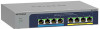
MS108UP switch
Sample connections
PTZ camera
Non PoE
PoE+
3. Check the LEDs
When you connect the power adapter to the switch and plug the cable into an electrical
outlet, the LEDs indicate the status:
LED
Description
Power LED
Solid green
: The switch is powered on and operating normally.
Off
.
Power is not supplied to the switch.
PoE Max LED
(The status of
the switch’s PoE
budget.)
Off
: Sufficient (more than 7W of) PoE power is available.
Solid yellow
: Less than 7W of PoE power is available.
Blinking yellow
: At least once during the previous two minutes, less
than 7W of PoE power was available
.
Left Port LED
Solid green
: 2.5 Gbps link on this port.
Blinking green
: 2.5 Gbps activity on this port.
Solid yellow
: 1000 Mbps or 100 Mbps link on this port.
Blinking yellow
: 1000 Mbps or 100 Mbps activity on this port.
Off
. No link is detected on this port.
Right Port LED
Solid Green
: The port is delivering PoE power.
Off
: The port is not delivering PoE power.
Solid yellow
: A PoE fault occurred.
Technical specifications
Specification
Description
Network interfaces
RJ‑45 connectors that support 100BASE‑TX,
1000BASE‑T, and 2.5GBASE‑T
Ports
8
PoE
Ports 1–4: PoE++ (802.3bt)
Ports 5–8: PoE+ (802.3at)
PoE budget
230W
Power adapter
54V @ 4.7A DC input
Power consumption
270.5W
Dimensions (W x D x H)
8.27 x 5.51 x 1.58 in. (210 x 140 x 40 mm)
Weight
1.98 lb
(900 g)
Operating temperature
32 to 104° F (0 to 40° C)
Operating humidity
10 to 90% relative humidity, noncondensing
Maximum operating altitude
10,000 ft. (3,000 m)
Storage temperature
–4 to 158° F (–20 to 70° C)
Storage humidity
5 to 95% relative humidity, noncondensing
Maximum storage altitude
10,000 ft. (3,000 m)
Electromagnetic certifications
and compliance
EMC class B device, FCC, ISED, CE, RCM, VCCI, BSMI,
CCC, KC
Safety certifications
CB, CE LVD, CSA, BSMI, CCC
WAC540
PoE+ AP
PoE++
ReadyNAS
Computer
NOTE:
We recommend that you use a Category 5e (Cat 5e) cable or higher‑rated
cable for Gigabit Ethernet connections.
WARNING:
Before connecting this switch to outdoor cables or devices, see
for safety and warranty information.
This switch is designed for indoor use only. If you want to connect it to a device located
outdoors, the outdoor device must be properly grounded and surge protected, and you
must install an Ethernet surge protector inline between the switch and the outdoor device.
Failure to do so can damage the switch.