Netgear XCM8806 Chassis Command Line Interface Manual
Netgear XCM8806 Chassis Manual
 |
View all Netgear XCM8806 Chassis manuals
Add to My Manuals
Save this manual to your list of manuals |
Netgear XCM8806 Chassis manual content summary:
- Netgear XCM8806 Chassis | Command Line Interface Manual - Page 1
8800 Series Chassis Switch Hardware Installation Guide 350 East Plumeria Drive San Jose, CA 95134 USA February 2011 202-10803-01 v1.0 - Netgear XCM8806 Chassis | Command Line Interface Manual - Page 2
8800 Series Chassis Switch Hardware Installation Guide © 2011 NETGEAR, Inc. All rights reserved. No part of product updates, or get support online, visit us at http://support.netgear.com. Phone (US & Canada only): 1-888-NETGEAR Phone (Other Countries): See Support information card. Trademarks - Netgear XCM8806 Chassis | Command Line Interface Manual - Page 3
Chapter 1 About the 8800 Series Chassis Switches Overview of the 8800 Series Chassis Switches 8 Full-Duplex Support 8 Management Ports 8 External Compact Flash Memory Card 9 8800 Series 6-slot Chassis Switch XCM8806 9 8800 Series 10-slot Chassis Switch XCM8810 11 Chapter 2 8800 Series Modules - Netgear XCM8806 Chassis | Command Line Interface Manual - Page 4
User Manual Power Requirements 39 PoE Devices 39 Power Supply Requirements 39 AC Power Cord Requirements 40 Uninterruptible Power Supply Requirements 40 Applicable Industry Standards 41 Chapter 5 Install an 8800 Series Chassis Unpack the XCM8806 Chassis 43 Unpack the XCM8810 Chassis 45 - Netgear XCM8806 Chassis | Command Line Interface Manual - Page 5
New Template User Manual Chapter 9 AC Power Cord Retainers AC Power Cord Retainer for the XCM8810 Chassis 10-slot 82 Install the Power Cord Retainer 82 Disconnect an XCM8810 Power Cord 84 Power Cord Retainer for the XCM8806 Chassis 6-Slot 84 Install the Power Cord Retainer 84 Remove the XCM8806 - Netgear XCM8806 Chassis | Command Line Interface Manual - Page 6
New Template User Manual Auswahl der Stromkabel 116 Austauschen und Entsorgen von Batterien 117 Lichtleiteranschlüsse: Optische Sicherheit 117 Appendix B Technical Specifications 8800 Series Chassis Switch XCM8810 120 8800 Series Chassis Switch XCM8806 123 Modules for 8800 Series Switches 125 - Netgear XCM8806 Chassis | Command Line Interface Manual - Page 7
: • Overview of the XCM8800 Series Switches • Full-Duplex Support on page 8 • Management Ports on page 8 • External Compact Flash Memory Card on page 9 • 8800 Series 6-slot Chassis Switch XCM8806 on page 9 • 8800 Series 10-slot Chassis Switch XCM8810 on page 11 For information about installing the - Netgear XCM8806 Chassis | Command Line Interface Manual - Page 8
about configuring a switch, see the NETGEAR 8800 Series Chassis Switch User Manual and the NETGEAR 8800 Series Chassis Switch CLI Manual. Full-Duplex Support The switches provide full-duplex support for all ports. Full-duplex support means that frames can be transmitted and received simultaneously - Netgear XCM8806 Chassis | Command Line Interface Manual - Page 9
8800 Series Chassis Switch Hardware Installation Guide access into the switch. This access allows you NETGEAR 8800 Series Chassis Switch User Manual for more information regarding the use of the external compact flash memory card. The external compact flash slot supports third-party compact flash - Netgear XCM8806 Chassis | Command Line Interface Manual - Page 10
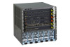
8800 Series Chassis Switch Hardware Installation Guide Figure 1. Front of the XCM8806 Chassis The following figure shows the rear panel of the XCM8806 chassis. Figure 2. Rear panel of the XCM8806 Chassis The rear panel of the XCM8806 chassis provides: • Chassis serial number • Ethernet MAC address - Netgear XCM8806 Chassis | Command Line Interface Manual - Page 11
Chassis Switch Hardware Installation Guide 8800 Series 10-slot Chassis Switch XCM8810 The XCM8810 chassis includes the following physical features: • One 10-slot chassis modules and I/O modules installed, the XCM8810 chassis can support up to 48 gigabits per second of bandwidth per slot. The - Netgear XCM8806 Chassis | Command Line Interface Manual - Page 12
8800 Series Chassis Switch Hardware Installation Guide The following figure shows the rear panel of the XCM8810 chassis. Figure 4. Rear panel of the XCM8810 Chassis The rear panel of the XCM8810 chassis provides: • Chassis serial number • Ethernet MAC address of the switch • Symbols of safety - Netgear XCM8806 Chassis | Command Line Interface Manual - Page 13
2. 8800 Series Modules 2 This chapter describes modules for the 8800 series switches and includes the following sections: • Overview of the 8800 Series Modules on page 14 • Supervisory Module on page 14 • I/O Modules on page 17 Chapter 2. 8800 Series Modules | 13 - Netgear XCM8806 Chassis | Command Line Interface Manual - Page 14
Chassis Switch Hardware Installation Guide the operating status of the modules. The 8800 series switches support these modules: • 8800 Series Supervisory Module XCM88S1 • lower-numbered slot becomes the primary Supervisory module. In the XCM8810 switch this is slot 5; in the XCM8806 switch, this - Netgear XCM8806 Chassis | Command Line Interface Manual - Page 15
without disrupting network services. • If you remove the primary Supervisory module while the switch is operating, the backup Supervisory module performs a soft reset and then becomes the primary Supervisory module. For example, in an 8800 Series Chassis Switch XCM8810 with a primary Supervisory - Netgear XCM8806 Chassis | Command Line Interface Manual - Page 16
8800 Series Chassis Switch Hardware Installation Guide The Supervisory module has a slot for the more information.) Note: See the NETGEAR 8800 Series Chassis Switch User Manual and the NETGEAR 8800 Series Chassis Switch CLI Manual for more information about numbering conventions for the modules - Netgear XCM8806 Chassis | Command Line Interface Manual - Page 17
8800 Series Chassis Switch Hardware Installation Guide Note: The LEDs on the management Ethernet port as mismatch. Note: See the NETGEAR 8800 Series Chassis Switch User Manual and the NETGEAR 8800 Series Chassis Switch CLI Manual for feature-specific information related to XCM8000 series modules. - Netgear XCM8806 Chassis | Command Line Interface Manual - Page 18
8800 Series Chassis Switch Hardware Installation Guide 8800 Series 48-port 10/100/1000 Base device, as well as the usual Ethernet connection, using a single cable. The 48 G Copper module supports the IEEE 802.3af PoE specification. In the default configuration of the XCM8848T module I/O module, all - Netgear XCM8806 Chassis | Command Line Interface Manual - Page 19
8800 Series Chassis Switch Hardware Installation Guide 8800 Series 8-port 10GBase-XFP Module XCM8808X This module has eight unpopulated XFP-based 10-gigabit Ethernet ports. Figure 7. 8800 Series 8-port 10GBase-XFP Module - Netgear XCM8806 Chassis | Command Line Interface Manual - Page 20
8800 Series Chassis Switch Hardware Installation Guide The 8800 Series 24-port 1000Base-X SFP Module module has the following LEDs: • Module status • Module diagnostics • Port status For information about the LEDs and - Netgear XCM8806 Chassis | Command Line Interface Manual - Page 21
8800 Series Chassis Switch Hardware Installation Guide Port LEDs on Non-PoE Modules The following table describes the LED meanings for each port on the non-PoE XCM8000 series I/O modules and the - Netgear XCM8806 Chassis | Command Line Interface Manual - Page 22
3. Power Supply Units 3 The XCM8800 Series Chassis Switch are powered by 100-240VAC Power Supply Units (PSUs). AC power supplies in the 8800 series switches are fully fault tolerant and load-sharing - Netgear XCM8806 Chassis | Command Line Interface Manual - Page 23
8800 Series Chassis Switch Hardware Installation Guide Overview of the 100-240VAC Power Supply Unit XCM88PS1 The attempt to open the PSU enclosure for any reason; the PSU does not contain user-serviceable parts. In the event of failure, return the defective PSU for repair or replacement. Chapter 3. - Netgear XCM8806 Chassis | Command Line Interface Manual - Page 24
8800 Series Chassis Switch Hardware Installation Guide LEDs The front panel of the PSU provides status LEDs. The following table describes the LED activity. Table 5. LEDs on the PSU PSU Condition Power - Netgear XCM8806 Chassis | Command Line Interface Manual - Page 25
8800 Series Chassis Switch Hardware Installation Guide Specifications The XCM88PS1 PSU functions from 90 V to 264 V input is in the 220 V high-line output power range. More installed PSUs are needed to support the load if the low-line power range is used to power the switch. The software determines - Netgear XCM8806 Chassis | Command Line Interface Manual - Page 26
4. Site Preparation 4 This chapter includes the following sections: • Plan Your Site on page 27 • Site Requirements on page 27 • Cable Requirements on page 33 • Power Requirements on page 39 • Applicable Industry Standards on page 41 The information in this chapter is intended for the system - Netgear XCM8806 Chassis | Command Line Interface Manual - Page 27
8800 Series Chassis Switch Hardware Installation Guide Plan Your Site By carefully planning your site, you can maximize the performance of your existing network and ensure that it is ready to migrate - Netgear XCM8806 Chassis | Command Line Interface Manual - Page 28
8800 Series Chassis Switch Hardware Installation Guide Information about major building codes is located at the following closet: • Be sure that your system is easily accessible for installation and service. See Rack Specifications and Recommendations on page 31 for information. • Use appropriate - Netgear XCM8806 Chassis | Command Line Interface Manual - Page 29
8800 Series Chassis Switch Hardware Installation Guide • Be sure that each wiring closet has a suitable ground. All distribution racks and equipment installed in the closet should be grounded. • Be sure that all - Netgear XCM8806 Chassis | Command Line Interface Manual - Page 30
8800 Series Chassis Switch Hardware Installation Guide or • Place patch panels between two sets of three adjacent modules, as shown in the following figure. Figure 10. Airflow through the XCM8810 Chassis Electrostatic Discharge Your system has to be protected from static electricity or electrostatic - Netgear XCM8806 Chassis | Command Line Interface Manual - Page 31
typically on the base). • The rack needs to meet earthquake safety requirements equal to that of the installed chassis. • The mounting holes should be flush with the rails to accommodate the chassis. • The rack should support approximately 600 pounds (272 kilograms). Chapter 4. Site Preparation | 31 - Netgear XCM8806 Chassis | Command Line Interface Manual - Page 32
8800 Series Chassis Switch Hardware Installation Guide Protective Grounding for the Rack Use a rack grounding kit Space Requirements for the Rack Provide enough space in front of and behind the switch so that you can service it easily. Allow a minimum of 48 inches (122 cm) in front of the rack and 24 - Netgear XCM8806 Chassis | Command Line Interface Manual - Page 33
8800 Series Chassis Switch Hardware Installation Guide Securing the Rack The rack should be attached to the on page 38 Cabling Standards NETGEAR recommends using the Building Industry Consulting Service International (BICSI) Registered Communications Distribution Designer (RCDD), which is globally - Netgear XCM8806 Chassis | Command Line Interface Manual - Page 34
8800 Series Chassis Switch Hardware Installation Guide Cable Labeling and Record Keeping A reliable cable labeling system is . • Know the types of network devices that your cabling infrastructure can support. Consider the following recommendations when setting up a cable labeling system suitable - Netgear XCM8806 Chassis | Command Line Interface Manual - Page 35
8800 Series Chassis Switch Hardware Installation Guide Cable Distances The following table shows cable media types and maximum distances that support reliable transmission in accordance with international standards. Table 6. Media Types and Maximum Distances Standard 1000BASE-SX (850 nm optical - Netgear XCM8806 Chassis | Command Line Interface Manual - Page 36
8800 Series Chassis Switch Hardware Installation Guide The following figure shows examples of connector jacket types cable to your network equipment: • Examine cable for cuts, bends, and nicks. • Support cable using a cable manager that is mounted above connectors to avoid unnecessary weight on the - Netgear XCM8806 Chassis | Command Line Interface Manual - Page 37
8800 Series Chassis Switch Hardware Installation Guide CAUTION: Unshielded twisted pair (UTP) cable can build up ESD charges when being pulled into a new installation. Before connecting any category 5 UTP cable to the - Netgear XCM8806 Chassis | Command Line Interface Manual - Page 38
Chassis Switch Hardware Installation Guide Note: Kinks and sharp bends can destroy or impair the cable's ability to convey light pulses accurately from one end of the cable to the other. Use care in dressing the optical fiber cables: provide satisfactory strain relief to support layer problems that - Netgear XCM8806 Chassis | Command Line Interface Manual - Page 39
8800 Series Chassis Switch Hardware Installation Guide Power Requirements This section describes power requirements, For power specifications of the power supplies, see Appendix B, Technical Specifications. WARNING! The chassis does not have a switch for turning power to the unit on and off. For - Netgear XCM8806 Chassis | Command Line Interface Manual - Page 40
8800 Series Chassis Switch Hardware Installation Guide AC Power Cord Requirements Should you use your own, make sure that the power cord you use is certified for the country of end use - Netgear XCM8806 Chassis | Command Line Interface Manual - Page 41
8800 Series Chassis Switch Hardware Installation Guide Note: NETGEAR recommends that you use a UPS that provides online protection. Calculating Volt-Amperage Requirements To determine the minimum volt-amperage requirements for your UPS: 1. - Netgear XCM8806 Chassis | Command Line Interface Manual - Page 42
Requirements on page 48 • Rack Mount the 8800 Series Chassis on page 48 • Ground the 8800 Series Chassis on page 50 This chapter describes how to install the following chassis models: • XCM8806 chassis • XCM8810 chassis The 8800 series chassis fits into a standard 19-inch (48.26 cm) rack - Netgear XCM8806 Chassis | Command Line Interface Manual - Page 43
8800 Series Chassis Switch Hardware Installation Guide Unpack the XCM8806 Chassis CAUTION: The XCM8806 chassis weighs almost 65 pounds. Proper lifting and moving of the chassis requires two people. To unpack the XCM8806 chassis: 1. Open the top flaps and remove the accessories and documentation pack - Netgear XCM8806 Chassis | Command Line Interface Manual - Page 44
8800 Series Chassis Switch Hardware Installation Guide 3. Slide the shipping carton up over the XCM8806 chassis. Figure 18. Removing the carton from the XCM8806 Chassis 4. Unwrap the chassis. 5. At each side of the chassis, place one hand in an empty power supply bay and the other hand in the - Netgear XCM8806 Chassis | Command Line Interface Manual - Page 45
-inch support bracket • Documentation pack with ESD-preventive wrist strap Note: Save all packaging, clip locks, and box pieces for future use in the event that the XCM8806 chassis has to be moved to another location or returned. Unpack the XCM8810 Chassis CAUTION: The XCM8810 chassis weighs almost - Netgear XCM8806 Chassis | Command Line Interface Manual - Page 46
8800 Series Chassis Switch Hardware Installation Guide 2. Open the flaps and remove the contents from the upper shipping carton. Figure 21. Removing contents from the upper shipping carton 3. Lift the XCM8810 shipping carton up and off the chassis. Figure 22. Unpacking the XCM8810 Chassis 46 | - Netgear XCM8806 Chassis | Command Line Interface Manual - Page 47
). CAUTION: Do not use the fan tray handle to lift or maneuver the XCM8810 chassis. This handle is not designed to support the weight of the chassis. 6. Carefully lift the chassis off the shipping pallet and onto the floor as shown in the following figure. Figure 24. Correct method for lifting - Netgear XCM8806 Chassis | Command Line Interface Manual - Page 48
8800 Series Chassis Switch Hardware Installation Guide Verify that the following items are included in the shipping carton: • XCM8810 chassis with eight installed blank front panels • Power cord retainer • 19-inch support bracket • Documentation pack with ESD-preventive wrist strap Note: Save all - Netgear XCM8806 Chassis | Command Line Interface Manual - Page 49
bracket to the rack 4. Lift the back of the empty 8800 series chassis onto the support bracket. 5. Slowly guide the chassis into the rack until the mounting brackets are flush against the rack uprights. 6. Secure the chassis to the rack using eight rack mounting screws. (Screws are not provided - Netgear XCM8806 Chassis | Command Line Interface Manual - Page 50
Installation Guide Figure 27. Securing the XCM8810 Chassis to a rack 7. Remove the support bracket from the rack after the chassis is secured. Save the bracket for future use if you remove the chassis from the rack. Ground the 8800 Series Chassis Although grounding the 8800 series chassis is - Netgear XCM8806 Chassis | Command Line Interface Manual - Page 51
8800 Series Chassis Switch Hardware Installation Guide To ground the chassis: 1. Locate the grounding point on the back of the chassis (Figure 28 and Figure 29). Figure 28. Back of XCM8806 Chassis Figure 29. Back of XCM8810 Chassis 2. Strip 0.5-inch (1.2-cm) of insulation from the stranded copper - Netgear XCM8806 Chassis | Command Line Interface Manual - Page 52
Chassis Switch Hardware Installation Guide CAUTION: Be sure that no copper is visible between the lug and the cable insulation. 4. Crimp the lug onto the cable according to the manufacturer's specifications. 5. Insert the screws through the lug and into the grounding point on the back of the chassis - Netgear XCM8806 Chassis | Command Line Interface Manual - Page 53
6 6. Install Power Supply Units in the Switches This chapter includes the following topics: • Safety on page 54 • Power Supply Cords for AC Power Supplies on page 55 • Install a PSU on page 56 The chapter describes how to install and remove each power supply model used with the 8800 series switches. - Netgear XCM8806 Chassis | Command Line Interface Manual - Page 54
8800 Series Chassis Switch Hardware Installation Guide Safety Only trained service personnel should perform service to NETGEAR switches and their components. Trained service personnel have read all related installation manuals, have the technical training and experience necessary to be aware of the - Netgear XCM8806 Chassis | Command Line Interface Manual - Page 55
8800 Series Chassis Switch Hardware Installation Guide Power Supply Cords for AC Power Supplies The power supply cords provided in the package with the PSU are shown in the following table. Table 7. - Netgear XCM8806 Chassis | Command Line Interface Manual - Page 56
8800 Series Chassis Switch Hardware Installation Guide Each power cord is enclosed in a plastic wrapper must not attempt to open the PSU enclosure for any reason; the PSU does not contain user-serviceable parts. In the event of failure, return the defective PSU for repair or replacement. CAUTION: - Netgear XCM8806 Chassis | Command Line Interface Manual - Page 57
8800 Series Chassis Switch Hardware Installation Guide Install the 100-240VAC PSU XCM88PS1 CAUTION: Make sure that the PSU circuit is not overloaded. Use proper over-current protection, such as a circuit-breaker, - Netgear XCM8806 Chassis | Command Line Interface Manual - Page 58
8800 Series Chassis Switch Hardware Installation Guide Figure 31. Inserting a PSU into the power supply bay 4. Secure the PSU in the power supply bay by pushing down on the locking handle until - Netgear XCM8806 Chassis | Command Line Interface Manual - Page 59
Chassis Switch Hardware Installation Guide a. Remove the power cord retainer as described in Disconnect an XCM8810 Power Cord on page 84 or Remove the XCM8806 Power Cord Wearing thermal protective gloves, place both hands underneath the PSU to support the weight as it is pulled out from the switch. - Netgear XCM8806 Chassis | Command Line Interface Manual - Page 60
7. Install Modules and Establish Initial Management Access 7 The chapter describes how to install the Supervisory modules and I/O modules in the 8800 series switches and how to set up initial management access for the switch. All module types are hot-swappable. The chapter includes the following - Netgear XCM8806 Chassis | Command Line Interface Manual - Page 61
8800 Series Chassis Switch Hardware Installation Guide Module Slot Assignments The specific slot locations for I/O modules and Supervisory modules in the chassis are as follows: • XCM8810 switch - Slots 1, 2, 3, 4, 7, 8, 9, and 10 can accommodate only I/O modules. - Slot 5/A can accommodate only an - Netgear XCM8806 Chassis | Command Line Interface Manual - Page 62
8800 Series Chassis Switch Hardware Installation Guide latches indicate that the module is a Supervisory module, and wrist and connect the metal end to the ground receptacle at the top left corner of the chassis. 2. Select a slot for the module. (See Module Slot Assignments on page 61.) CAUTION: - Netgear XCM8806 Chassis | Command Line Interface Manual - Page 63
8800 Series Chassis Switch Hardware Installation Guide Note: Any unoccupied module slot in the chassis should have a blank faceplate installed to ensure satisfactory protection from EMI and to maintain adequate airflow through the chassis. 4. Remove the module from the antistatic packaging as - Netgear XCM8806 Chassis | Command Line Interface Manual - Page 64
8800 Series Chassis Switch Hardware Installation Guide 7. Use both hands to latch the injector/ejector module packaging for future use. Leave the ESD-preventive wrist strap permanently connected to the chassis so that the strap is always available when you need to handle ESD-sensitive components. - Netgear XCM8806 Chassis | Command Line Interface Manual - Page 65
8800 Series Chassis Switch Hardware Installation Guide Connect Network Interface Cables Use the appropriate type of cable to connect the ports of your switch to another switch or router. Working carefully, one - Netgear XCM8806 Chassis | Command Line Interface Manual - Page 66
Chassis Switch Hardware Installation Guide Use series. Displaying Slot Status Information Assuming the module has no problems, the command show slot (where the NETGEAR 8800 Series Chassis Switch User Manual and the NETGEAR 8800 Series Chassis Switch CLI Manual. Remove an XCM8000 - Netgear XCM8806 Chassis | Command Line Interface Manual - Page 67
8800 Series Chassis Switch Hardware Installation Guide CAUTION: Be sure to turn each captive screw only 90 on the PCB or the pins on any of the connectors. 4. Slide the module out of the chassis slot. 5. Immediately place the module into the anti-static bag to protect it from potential ESD damage. - Netgear XCM8806 Chassis | Command Line Interface Manual - Page 68
8800 Series Chassis Switch Hardware Installation Guide Note: Leave the ESD-preventive wrist strap permanently connected to the chassis so that over one or more chassis slots. You can remove or install a blank front panel at any time without disrupting network services. Complete the action of - Netgear XCM8806 Chassis | Command Line Interface Manual - Page 69
8800 Series Chassis Switch Hardware Installation Guide Verify that the EMI gasket is on the top of the panel and the stenciled part number is right side up. Figure 38. Blank front panels in an 8800 Series Chassis 3. Use a #2 Phillips screwdriver to tighten the captive screws at each end of the blank - Netgear XCM8806 Chassis | Command Line Interface Manual - Page 70
8800 Series Chassis Switch Hardware Installation Guide 2. Loosen the captive screw at each end of the blank front panel, using a #2 Phillips screwdriver. Figure 39. Captive screw on a blank front panel 3. Remove the - Netgear XCM8806 Chassis | Command Line Interface Manual - Page 71
Chassis Switch Hardware Installation Guide Install or Remove an External Compact Flash Memory Card You do not need to power off the system or remove the Supervisory module from the chassis command, see the NETGEAR 8800 Series Chassis Switch User Manual. 2. Attach the ESD-preventive wrist strap - Netgear XCM8806 Chassis | Command Line Interface Manual - Page 72
8800 Series Chassis Switch Hardware Installation Guide 4. Press the release pin until the card releases , see Connector Pinouts on page 126. Logging In for the First Time To log in and manually configure the IP settings: 1. Connect a terminal or PC with terminal-emulation software to the Supervisory - Netgear XCM8806 Chassis | Command Line Interface Manual - Page 73
8800 Series Chassis Switch Hardware Installation Guide login: admin Administrator capabilities allow you to access all name (for example, NETGEAR XCM8810>) in its prompt. For more information about how to assign a specific system name, see the ProSafe 8800 Chassis Switch User Manual. 6. Assign an IP - Netgear XCM8806 Chassis | Command Line Interface Manual - Page 74
8. Install or Remove Cards 8 This chapter includes the following sections: • Install a PoE Daughter Card XCM88P on page 75 • Remove a PoE Card XCM88P on page 77 • Install an Option Card XCM888F in the Supervisory Module on page 77 • Remove a Supervisory Module Option Card on page 79 Chapter 8. - Netgear XCM8806 Chassis | Command Line Interface Manual - Page 75
8800 Series Chassis Switch Hardware Installation Guide Install a PoE Daughter Card XCM88P The PoE to the ground receptacle at the top left corner of the chassis. 2. Remove the I/O module from the 8800 series switch, following the instructions in Remove an XCM8000 Series Module on page 66. Set - Netgear XCM8806 Chassis | Command Line Interface Manual - Page 76
8800 Series Chassis Switch Hardware Installation Guide Following the sequence indicated in the following figure, carefully press the connectors into place. Make sure that all the connectors seat securely. Figure 43. Seating - Netgear XCM8806 Chassis | Command Line Interface Manual - Page 77
8800 Series Chassis Switch Hardware Installation Guide 7. Re-install the I/O module in the 8800 series switch following the instructions in Install an XCM8000 Series Module on page 62. Remove a PoE Card XCM88P To remove a PoE card: 1. Attach the ESD-preventive wrist strap to your - Netgear XCM8806 Chassis | Command Line Interface Manual - Page 78
8800 Series Chassis Switch Hardware Installation Guide To install an option card in a Supervisory module: 1. Attach the ESD-preventive wrist strap to your bare wrist and connect the metal end to the ground receptacle on the top-left corner of the switch chassis. 2. Remove the Supervisory module from - Netgear XCM8806 Chassis | Command Line Interface Manual - Page 79
8800 Series Chassis Switch Hardware Installation Guide 7. At the back of the option card, align and finger-tighten the captive retaining screws to secure the card in place. Figure 47. Securing the Option card XCM88F 8. Re-install the Supervisory module, following the instructions in Install an - Netgear XCM8806 Chassis | Command Line Interface Manual - Page 80
8800 Series Chassis Switch Hardware Installation Guide 5. Using the handle on the option card, pull straight back from the Supervisory module to disconnect the option card from the connectors on the Supervisory - Netgear XCM8806 Chassis | Command Line Interface Manual - Page 81
are provided with the 8800 series switches. This chapter includes the following sections: • AC Power Cord Retainer for the XCM8810 Chassis 10-slot on page 82 • Power Cord Retainer for the XCM8806 Chassis 6-Slot on page 84 WARNING! These switches do not have a switch for turning the power of the unit - Netgear XCM8806 Chassis | Command Line Interface Manual - Page 82
8800 Series Chassis Switch Hardware Installation Guide AC Power Cord Retainer for the XCM8810 Chassis 10-slot Connect all AC power cords before you install the power cord retainer. You need the following tools and equipment to install or remove - Netgear XCM8806 Chassis | Command Line Interface Manual - Page 83
8800 Series Chassis Switch Hardware Installation Guide 4. Make sure that each AC power cord is firmly plugged into the power outlet as shown in the following figure. Figure 51. Power cord plugged into the XCM8810 Switch power outlet 5. Align the AC power cord retainer over the AC power cord ends as - Netgear XCM8806 Chassis | Command Line Interface Manual - Page 84
8800 Series Chassis Switch Hardware Installation Guide Disconnect an XCM8810 Power Cord To disconnect a power cord: 1. Attach the ESD-preventive wrist strap to your bare wrist and connect the metal end to the ground receptacle on the top left corner of the switch chassis. 2. Disconnect the AC power - Netgear XCM8806 Chassis | Command Line Interface Manual - Page 85
8800 Series Chassis Switch Hardware Installation Guide Figure 54. Installing and routing the AC power cords 3. Hold the power cord retainer as shown in the following figure. Figure 55. XCM8806 AC power - Netgear XCM8806 Chassis | Command Line Interface Manual - Page 86
8800 Series Chassis Switch Hardware Installation Guide 1 = Captive screw Figure 56. Securing the XCM8806 AC power cord retainer 5. Starting from the left, lay the first four power cords into the retainer (see - Netgear XCM8806 Chassis | Command Line Interface Manual - Page 87
8800 Series Chassis Switch Hardware Installation Guide Remove the XCM8806 Power Cord Retainer To remove the power cord retainer: 1. Attach the ESD-preventive wrist strap to your wrist and connect the metal - Netgear XCM8806 Chassis | Command Line Interface Manual - Page 88
10. Cable Management 10 This chapter includes the following sections: • Cable Management on page 89 • Cable Holders and Cable Clips on page 89 The cable holders and cable clips provide a way to organize and contain masses of cables connected to a switch. This chapter describes how to install and - Netgear XCM8806 Chassis | Command Line Interface Manual - Page 89
8800 Series Chassis Switch Hardware Installation Guide Cable Management Interlocking cable holders and cable clips for the switches provide free-standing, rigid structural support for individual cables and cable bundles in front of the switch. You can use the cable holders and cable clips - Netgear XCM8806 Chassis | Command Line Interface Manual - Page 90
8800 Series Chassis Switch Hardware Installation Guide The following figure shows the cable holders and clips being used to manage a group of cables. Figure 58. Cable holders and clips Cable Holders Each - Netgear XCM8806 Chassis | Command Line Interface Manual - Page 91
8800 Series Chassis Switch Hardware Installation Guide Figure 59. Connecting cable holders 2. Slide the ends together and push the cable holders together until you feel them snap into place. Figure 60. Connected - Netgear XCM8806 Chassis | Command Line Interface Manual - Page 92
8800 Series Chassis Switch Hardware Installation Guide Cable Clips To connect the cable clips: 1. Hold two clips next to each other with the split sides facing the same way.Slide the connecting - Netgear XCM8806 Chassis | Command Line Interface Manual - Page 93
11. Replace 8800 Series Chassis Components 11 This chapter describes how to replace components in the following switches: • XCM8810 switch • XCM8806 switch The chapter includes the following sections: • Replace the Fan Tray on page 93 • Replace the PSU/Fan Controller on page 97 Replace - Netgear XCM8806 Chassis | Command Line Interface Manual - Page 94
8800 Series Chassis Switch Hardware Installation Guide 2. Locate the captive screws at the top and bottom of the fan tray. 3. Use a #2 Phillips screwdriver to loosen each captive screw (see Figure 63 and Figure 64). Figure 63. Removing the Fan Tray from the XCM8810 Switch Figure 64. Removing the fan - Netgear XCM8806 Chassis | Command Line Interface Manual - Page 95
Series Chassis Switch Hardware Installation Guide WARNING! Be sure that all fan blade motion has ceased before continuing to remove the fan tray. 5. Support the the fan tray slot. CAUTION: Be sure that both hands are used to support the weight of the fan tray during removal. Note: Leave the ESD- - Netgear XCM8806 Chassis | Command Line Interface Manual - Page 96
8800 Series Chassis Switch Hardware Installation Guide Figure 65. Installing the Fan Tray in the XCM8810 Switch Figure 66. Installing the Fan Tray in the XCM8806 Switch 3. Use a #2 Phillips screwdriver you need to touch ESD-sensitive components. 96 | Chapter 11. Replace 8800 Series Chassis Components - Netgear XCM8806 Chassis | Command Line Interface Manual - Page 97
Hardware Installation Guide Replace the PSU/Fan Controller The 8800 series switch has two PSU/fan controllers behind an access panel on the rear of the switch chassis. Note: The PSU/fan controllers are installed in the system before it is shipped to customers. For a new chassis installation, access - Netgear XCM8806 Chassis | Command Line Interface Manual - Page 98
8800 Series Chassis Switch Hardware Installation Guide 2. Locate the eight captive screws on the PSU/fan controller access cover at the back of the 8800 series switch (see Figure 67 and Figure 68). Figure 67. Removing the access cover from the XCM8810 Switch Figure 68. Removing the access cover from - Netgear XCM8806 Chassis | Command Line Interface Manual - Page 99
8800 Series Chassis Switch Hardware Installation Guide 3. Using a #2 Phillips screwdriver, loosen all eight captive to the ground receptacle on the front top-left corner of the switch. 2. Align the guide pins in the empty controller recess with the holes on the replacement PSU/fan controller. 3. - Netgear XCM8806 Chassis | Command Line Interface Manual - Page 100
8800 Series Chassis Switch Hardware Installation Guide 6. Push the access cover over the controller recess until the captive screws on the access cover are in alignment. 7. is always available when you need to handle ESD-sensitive components. 100 | Chapter 11. Replace 8800 Series Chassis Components - Netgear XCM8806 Chassis | Command Line Interface Manual - Page 101
Information on page 102 • Repack the XCM8810 Chassis on page 102 • Repack the XCM8806 Chassis on page 104 The chapter describes how to remove a 8800 series chassis from an equipment rack and repack the chassis for shipping. To repack a 8800 series chassis, use the original shipping crate or box - Netgear XCM8806 Chassis | Command Line Interface Manual - Page 102
Installation Guide Safety Information CAUTION: Correct lifting procedures for a 8800 series chassis require two or more people. Only trained service personnel should perform service to the switches and their components. Trained service personnel have read all related installation manuals, have - Netgear XCM8806 Chassis | Command Line Interface Manual - Page 103
fan tray handle to lift or maneuver the XCM8810 chassis. This handle is not designed to support the weight of the chassis. 6. Slowly guide the chassis out of the equipment rack using the support bracket for support. 7. Carefully lift the chassis off the support bracket and lower it onto wood pallet - Netgear XCM8806 Chassis | Command Line Interface Manual - Page 104
tray handle to lift or maneuver the XCM8806 chassis. This handle is not designed to support the weight of the chassis. 6. Slowly guide the chassis out of the equipment rack using the support bracket for support. 7. Carefully lift the chassis off the support bracket and lower it onto the foam cushion - Netgear XCM8806 Chassis | Command Line Interface Manual - Page 105
8800 Series Chassis Switch Hardware Installation Guide 8. Set the corner braces in place and slide the top of the shipping carton down and over the chassis. Figure 73. Placing the carton over the XCM8806 Chassis 9. Insert the clip locks. a. Squeeze the prongs together in the middle of the clip lock. - Netgear XCM8806 Chassis | Command Line Interface Manual - Page 106
can lead to personal injury or damage to the equipment. Only trained service personnel should perform service to the switches and their components. Trained service personnel have read all related installation manuals, have the technical training and experience necessary to be aware of the - Netgear XCM8806 Chassis | Command Line Interface Manual - Page 107
for use with this system. Failure to follow these instructions may damage the equipment or violate required safety and EMC regulations. • The chassis cover should only be removed by NETGEAR personnel. This system contains no customer serviceable components. Repairs to the system must be performed by - Netgear XCM8806 Chassis | Command Line Interface Manual - Page 108
8800 Series Chassis Switch Hardware Installation Guide • When you install equipment in a rack, load heavier devices in the lower half of the rack first to avoid making the rack top-heavy. • Only - Netgear XCM8806 Chassis | Command Line Interface Manual - Page 109
8800 Series Chassis Switch Hardware Installation Guide Do not connect a power supply to an electrical outlet when the power supply is not installed in the chassis; doing so would expose a hazardous energy and poses a potential shock and fire hazard. Do not put your hand into an open power supply bay - Netgear XCM8806 Chassis | Command Line Interface Manual - Page 110
8800 Series Chassis Switch Hardware Installation Guide distribution where voltages do not exceed 240V AC. All installations should confirm that the product is reliably grounded according to the country's local electrical codes. - Netgear XCM8806 Chassis | Command Line Interface Manual - Page 111
8800 Series Chassis Switch Hardware Installation Guide (Type 2 or Type 4 ports as described in GR-1089-CORE, replaced by qualified service personnel only. Contact your NETGEAR service personnel for product replacement. Do not attempt to replace the battery. If these instructions are disregarded and - Netgear XCM8806 Chassis | Command Line Interface Manual - Page 112
8800 Series Chassis Switch Hardware Installation Guide • Never look at the transmit LED/laser through a installed into NETGEAR products Note: NETGEAR optical modules are tested to work in all supported NETGEAR switches. We recommend that all customers use NETGEAR optical modules in their NETGEAR - Netgear XCM8806 Chassis | Command Line Interface Manual - Page 113
8800 Series Chassis Switch Hardware Installation Guide Installation, Wartung und Ausbau eines Switch, einer Grundplatte oder einer seiner Komponenten dürfen nur von geschultem und qualifiziertem Servicepersonal durchgeführt werden! Geschulte und qualifizierte - Netgear XCM8806 Chassis | Command Line Interface Manual - Page 114
8800 Series Chassis Switch Hardware Installation Guide unterliegt den folgenden Voraussetzungen: (1) Das Gerät kann schädliche Interferenzen verursachen, und (2) das Gerät muss jede empfangene Interferenz zulassen, einschließlich einer Interferenz, die einen - Netgear XCM8806 Chassis | Command Line Interface Manual - Page 115
8800 Series Chassis Switch Hardware Installation Guide Leistungsspezifikationen für Netzteile von NETGEAR finden sich in Anhang B dieses Dokuments oder im Netzteil-Datenblatt unter http://www.netgear.com. WARNING! Die 325 W DC-Netzteile von - Netgear XCM8806 Chassis | Command Line Interface Manual - Page 116
8800 Series Chassis Switch Hardware Installation Guide • Vor dem Entfernen der Rückwand eines NETGEAR-Switch muss die gesamte Stromzufuhr unterbrochen werden. • Vor der Aufnahme von Arbeiten in der Nähe von Stromquellen alle - Netgear XCM8806 Chassis | Command Line Interface Manual - Page 117
8800 Series Chassis Switch Hardware Installation Guide • Die Mindestspezifikation für das flexible Kabel lautet: • Nr. 18 AWG (0,823 mm2) für Einheiten mit einem Bemessungsstrom von weniger als 10 A, oder • Nr. 18 AWG (0,823 mm2) - Netgear XCM8806 Chassis | Command Line Interface Manual - Page 118
8800 Series Chassis Switch Hardware Installation Guide • Niemals durch ein Vergrößerungsgerät auf die übertragende LED/den Laser schauen, wenn diese(r) eingeschaltet ist. • Niemals direkt auf einen Lichtleiteranschluss am Switch oder auf - Netgear XCM8806 Chassis | Command Line Interface Manual - Page 119
B. Technical Specifications This appendix includes the following technical specifications: • 8800 Series Chassis Switch XCM8810 on page 120 • 8800 Series Chassis Switch XCM8806 on page 123 • Modules for 8800 Series Switches on page 125 • 700 W Power Supply on page 126 • Connector Pinouts on page 126 - Netgear XCM8806 Chassis | Command Line Interface Manual - Page 120
8800 Series Chassis Switch Hardware Installation Guide 8800 Series Chassis Switch XCM8810 Table 10. 8800 Series Chassis Switch XCM8810 Technical Specifications Physical characteristics XCM8810 chassis Fan tray XCM8810FT Power supply XCM88PS1 PSU/fan controller XCM88FPB Safety standards North - Netgear XCM8806 Chassis | Command Line Interface Manual - Page 121
8800 Series Chassis Switch Hardware Installation Guide Table 10. 8800 Series Chassis Switch XCM8810 Technical Specifications (Continued) International EMC Certifications CISPR 22:1997 Class A (International Emissions) CISPR 24:1997 Class A (International Immunity) IEC/EN 61000-4-2 Electrostatic - Netgear XCM8806 Chassis | Command Line Interface Manual - Page 122
8800 Series Chassis Switch Hardware Installation Guide Table 10. 8800 Series Chassis Switch XCM8810 Technical Specifications (Continued) Acoustic Sound Sound power in accordance with EN 300 753 (10-1997) Sound power Normal: 70 dBA per ISO 7779 High: 75 - Netgear XCM8806 Chassis | Command Line Interface Manual - Page 123
8800 Series Chassis Switch Hardware Installation Guide 8800 Series Chassis Switch XCM8806 Physical Characteristics XCM8806 chassis Fan tray XCM8806FT Power supply XCM88PS1 PSU/fan controller XCM88FPB Safety Standards North American Safety of ITE European Safety of ITE International Safety of ITE - Netgear XCM8806 Chassis | Command Line Interface Manual - Page 124
8800 Series Chassis Switch Hardware Installation Guide Country-specific VCCI Class A (Japan Emissions) AS/NZS on sides & corners @ 39.4" - Netgear XCM8806 Chassis | Command Line Interface Manual - Page 125
8800 Series Chassis Switch Hardware Installation Guide Modules for 8800 Series Switches Table 11. Specifications for 8000 Series Modules and Option Cards Modules All modules Dimensions: 1.63 in. H x 15.26 in. W x 5.25 - Netgear XCM8806 Chassis | Command Line Interface Manual - Page 126
8800 Series Chassis Switch Hardware Installation Guide 700 W Power Supply Table 12. Specifications for the 100-240VAC Power Supply Unit Typical configuration Full configuration Input Output Power supply cord selection AC power - Netgear XCM8806 Chassis | Command Line Interface Manual - Page 127
8800 Series Chassis Switch Hardware Installation Guide Table 13. Pinouts for the DB-9 Console Connector (Continued) Function Pin Number Direction RTS (request to send) 7 Out CTS (clear to send) 8 In The following - Netgear XCM8806 Chassis | Command Line Interface Manual - Page 128
8800 Series Chassis Switch Hardware Installation Guide The following figure shows the port assignments for the MRJ21 connector. Port 1 Port 3 Port 5 Port 2 Port 4 Port 6 BD_232 Figure 76. Port-to-Pin Assignments in the MRJ21 Connector 128 | Appendix B. Technical Specifications - Netgear XCM8806 Chassis | Command Line Interface Manual - Page 129
8800 Series Chassis Switch Hardware Installation Guide Appendix B. Technical Specifications | 129 - Netgear XCM8806 Chassis | Command Line Interface Manual - Page 130
holder 90 cable labeling 34 cable management 37, 89 cabling standards ANSI 41 BICSI 33 Category 5 cable 37 chassis unpacking XCM8806 43-45 XCM8810 45-47 chassis-to-chassis heating 29 commands eject memorycard 71 show memorycard 71 show slot 66 synchronize 65 commercial building standards 41 compact - Netgear XCM8806 Chassis | Command Line Interface Manual - Page 131
8800 Series Chassis Switch Hardware Installation Guide Supervisory module 66 Supervisory option card 79 connectors DB-9 126 equipment rack grounding 32 mechanical recommendations 31 mounting holes 31 securing 33 service access 32 space requirements 32 ESD discharge from cable 37 system protection - Netgear XCM8806 Chassis | Command Line Interface Manual - Page 132
Chassis Switch Hardware Installation Guide L labeling system for cables 34 LEDs I/O modules 20 PoE ports 21 ports 21 power supply unit 24 logging in to the switch 72 low-line power 25 M MAC address XCM8806 switch 10 XCM8810 97 repacking XCM8810 switch 102 requirements airflow 30 chassis spacing 29 - Netgear XCM8806 Chassis | Command Line Interface Manual - Page 133
Chassis Switch Hardware Installation Guide RJ-45 cable 35 RJ-45 connector jackets 35 running cable. See cable, installing S safety requirements 106 See also environmental requirements safety standards 123 securing rack to floor 33 serial number XCM8806 switch 10 XCM8810 switch 12 service 15 support - Netgear XCM8806 Chassis | Command Line Interface Manual - Page 134
49 replacing fan tray 93 serial number 10 unpacking 43 XCM8808X module features 19 XCM8810 switch AC power cord retainer installing 82 removing 84 bandwidth 11 features 11 grounding option card features 16 installing 77 8800 Series Chassis Switch Hardware Installation Guide 134 | Index
-
 1
1 -
 2
2 -
 3
3 -
 4
4 -
 5
5 -
 6
6 -
 7
7 -
8
-
9
-
10
-
11
-
12
-
13
-
14
-
15
-
16
-
17
-
18
-
19
-
20
-
21
-
22
-
23
-
24
-
25
-
26
-
27
-
28
-
29
-
30
-
31
-
32
-
33
-
34
-
35
-
36
-
37
-
38
-
39
-
40
-
41
-
42
-
43
-
44
-
45
-
46
-
47
-
48
-
49
-
50
-
51
-
52
-
53
-
54
-
55
-
56
-
57
-
58
-
59
-
60
-
61
-
62
-
63
-
64
-
65
-
66
-
67
-
68
-
69
-
70
-
71
-
72
-
73
-
74
-
75
-
76
-
77
-
78
-
79
-
80
-
81
-
82
-
83
-
84
-
85
-
86
-
87
-
88
-
89
-
90
-
91
-
92
-
93
-
94
-
95
-
96
-
97
-
98
-
99
-
100
-
101
-
102
-
103
-
104
-
105
-
106
-
107
-
108
-
109
-
110
-
111
-
112
-
113
-
114
-
115
-
116
-
117
-
118
-
119
-
120
-
121
-
122
-
123
-
124
-
125
-
126
-
127
-
128
-
129
-
130
-
131
-
132
-
133
-
134
 |
 |

350 East Plumeria Drive
San Jose, CA 95134
USA
February 2011
202-10803-01
v1.0
8800 Series Chassis Switch
Hardware Installation Guide