Oki C9600hnColorSignage Hole Punch Kit Technician's Installation Guide
Oki C9600hnColorSignage Manual
 |
View all Oki C9600hnColorSignage manuals
Add to My Manuals
Save this manual to your list of manuals |
Oki C9600hnColorSignage manual content summary:
- Oki C9600hnColorSignage | Hole Punch Kit Technician's Installation Guide - Page 1
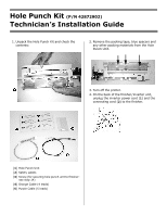
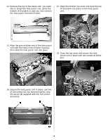
Hole Punch Kit (P/N 42872902) Technician's Installation Guide 1. Unpack the Hole Punch Kit and check the contents: 2. Remove the packing tape, blue spacers and any other packing materials from the Hole Punch Unit. 3. Turn off the printer. 4. On the back of the finisher/inverter unit, unplug the - Oki C9600hnColorSignage | Hole Punch Kit Technician's Installation Guide - Page 2
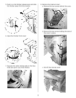
5. Push in on the finisher release lever and slide the finisher away from the inverter. 8. Remove the internal cover: a. Remove the two screws behind the cover. 6. Open the finisher front cover. b. Remove the two screws holding the side of the cover in place. 7. Squeeze the white locking tabs on - Oki C9600hnColorSignage | Hole Punch Kit Technician's Installation Guide - Page 3
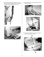
9. Remove the screws securing the rear cover (two on the left side [a] and one on the right side [b]), then remove the rear cover. a 10. Remove the two screws at either end of the hole punch blank. a 11. Swing up the finisher top cover (1) and lift b out the punch blank unit (2). 3 - Oki C9600hnColorSignage | Hole Punch Kit Technician's Installation Guide - Page 4
12. Remove the top of the blank unit: you need this to install the hole punch unit. Store the bottom of the blank in case you ever remove the hole punch from the finisher. 15. Open the finisher top cover and snap the top of the blank into place on the hole punch unit. 13. Align the pins at either - Oki C9600hnColorSignage | Hole Punch Kit Technician's Installation Guide - Page 5
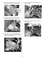
17. Insert the orange cable (4 leads) into the connector on the hole punch unit board. 20. Plug the orange cable into the connector on the main board. 18. Insert the purple cable (5 leads) into the connector on the hole punch unit board. 21. Plug the purple cable into the connector on the main - Oki C9600hnColorSignage | Hole Punch Kit Technician's Installation Guide - Page 6
22. Reinstall the back cover and secure it in place: two screws on the left side (a) and one screw on the right side (b). a 23. Reinstall the internal front cover and secure it with four screws. a b 6 - Oki C9600hnColorSignage | Hole Punch Kit Technician's Installation Guide - Page 7
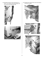
inverter. Make sure it locks in place. 28. Reattach the cable between the finisher and inverter and the finisher power cable. 29. Turn on the printer. 7 - Oki C9600hnColorSignage | Hole Punch Kit Technician's Installation Guide - Page 8
unit: a. With a suitable document open in a software application, select [File] → [Print]. b. Select the appropriate Oki printer, then click [Properties]. c. Click the [Job Options] tab. d. Under [Finisher], into the inverter. Make sure it locks in place. © 2005 Oki Data Americas, Inc. 58372901
-
 1
1 -
 2
2 -
 3
3 -
 4
4 -
 5
5 -
 6
6 -
 7
7 -
8
 |
 |
Hole Punch Kit
(P/N 42872902)
Technician°s Installation Guide
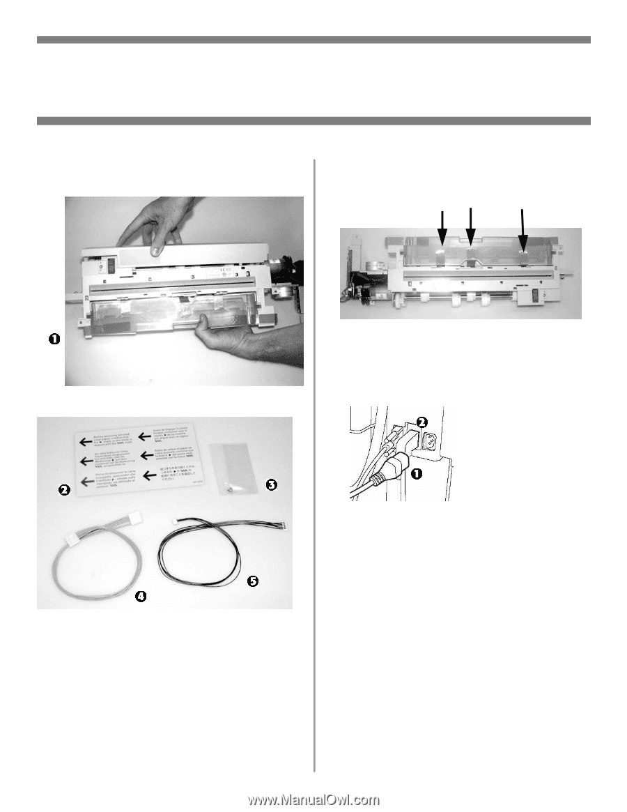
1. Unpack the Hole Punch Kit and check the
contents:
[
1
]
Hole Punch Unit
[
2
]
Safety Labels
[
3
]
Screw (for securing hole punch unit to finisher:
see step 14)
[
4
]
Orange Cable (4 leads)
[
5
]
Purple Cable (5 leads)
2. Remove the packing tape, blue spacers and
any other packing materials from the Hole
Punch Unit.
3. Turn off the printer.
4. On the back of the finisher/inverter unit,
unplug the inverter power cord (
1
) and the
connecting cord (
2
) to the finisher.