Panasonic AW-PH650NK1 AW-PH650 Operating Instructions
Panasonic AW-PH650NK1 Manual
 |
View all Panasonic AW-PH650NK1 manuals
Add to My Manuals
Save this manual to your list of manuals |
Panasonic AW-PH650NK1 manual content summary:
- Panasonic AW-PH650NK1 | AW-PH650 Operating Instructions - Page 1
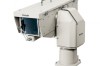
Outdoor Pan/Tilt Head AW-PH650N Printed in Japan F0406Y0 D Before attempting to connect, operate or adjust this product, please read these instructions completely. VQTB0104 - Panasonic AW-PH650NK1 | AW-PH650 Operating Instructions - Page 2
the user to the presence of important operating and maintenance (service) instructions in the literature accompanying the appliance. For CANADA This class and if not installed and used in accordance with the instruction manual, may cause harmful interference to radio communications. Operation of - Panasonic AW-PH650NK1 | AW-PH650 Operating Instructions - Page 3
and the point where they exit from the apparatus. 4) Follow all instructions. 5) Do not use this apparatus near water. 6) Clean only with when unused for long periods of time. 14) Refer all servicing to qualified service personnel. Servicing is required when the apparatus has been damaged in any way - Panasonic AW-PH650NK1 | AW-PH650 Operating Instructions - Page 4
Contents Introduction 4 Accessories 4 Precautions for use 4 Installation precautions 5 Mounting (Pan/tilt head 6 Precautions for installation 6 How to install 6 Mounting (AC adapter 7 Precautions for installation 7 How to install 7 Parts and their functions 9 Main unit (Pan/tilt head 9 - Panasonic AW-PH650NK1 | AW-PH650 Operating Instructions - Page 5
. (Batteries or other power supplies cannot be used.) The cable for connecting the power supply to the AC adapter is locally purchased. Read the operating instructions, and heed all the safety precautions to connect the cable. Do not turn the rotating part of the pan/tilt head by hand. If it - Panasonic AW-PH650NK1 | AW-PH650 Operating Instructions - Page 6
Mounting (Pan/tilt head) Precautions for installation Do not install this unit by suspending it, and do not install it on its side. Using the four pan/tilt head mounting holes, fasten the unit securely with bolts which are long enough. The mounting holes have a diameter of 3/8" (10 mm). Use - Panasonic AW-PH650NK1 | AW-PH650 Operating Instructions - Page 7
Mounting (AC adapter) Precautions for installation Be sure to use water-proof connecting cables. Be sure to keep AC power switched off during installation and connection. Before pressing the power switch on, make sure that all parts, including the housing and pan/tilt head, have been - Panasonic AW-PH650NK1 | AW-PH650 Operating Instructions - Page 8
Mounting (AC adapter) Connect the cables. (Refer to the "Connection".) Make the distance between the AC adapter and pan/tilt head less than the length (30 m) of the power cable supplied. Pan/tilt head Ventilation opening AC power input Pole mounting plate 8 - Panasonic AW-PH650NK1 | AW-PH650 Operating Instructions - Page 9
the cable. Install it at a distance within 30 mm from the connector. Waterproof the filter using tape or tube, for instance. Service connector (View of connector as seen from the cable) Cable Within 30 mm from connector Filter Power connector [POWER] The supplied power - Panasonic AW-PH650NK1 | AW-PH650 Operating Instructions - Page 10
Parts and their functions Housing unit Camera housing control board Connect the supplied camera cable. Air filter Air is taken in through the air filter. Replace it when it is clogged up. (Whenever the air filter needs replacement, - Panasonic AW-PH650NK1 | AW-PH650 Operating Instructions - Page 11
absolutely sure to tighten up the two fastening screws. Since malfunctions or other trouble may result if the screws are not tightened enough, be absolutely sure holes when the AC adapter is to be mounted on a pole or other support. DC output connector [DC15 V OUT] Connect this connector to the - Panasonic AW-PH650NK1 | AW-PH650 Operating Instructions - Page 12
Parts and their functions Supplied cable unit (VEEB0133) 24P round water-proof plug (male) Connect this to the multi connector [MULTI] on the main unit. RJ-45 modular plug Connect this to pan/tilt head controller. It can be extended up to 3281 ft. (1000 m). To extend - Panasonic AW-PH650NK1 | AW-PH650 Operating Instructions - Page 13
Parts and their functions (VEEB0152) 7P round water-proof plug (female) Connect this to the power connector [POWER] on the main unit. 7P round water-proof plug (male) Connect this to the DC output connector [DC 15V OUT] on the AC adapter. ( - Panasonic AW-PH650NK1 | AW-PH650 Operating Instructions - Page 14
Installation Installing the housing mount frame Attach the housing mount frame (supplied) to the rotary arm of the main unit. Attach the housing mount frame to the rotary arm as shown in the figure below. The screws must be installed together with the flat washers and spring washers (supplied). · - Panasonic AW-PH650NK1 | AW-PH650 Operating Instructions - Page 15
Installation Cable compensation circuit settings When the pan/tilt head and controller have been connected, the maximum allowable length of the connecting cables is 3281 ft. (1000 m) for the 10BASE-T straight cable (UTP category 5) and coaxial cable (BELDEN 8281). However, when using the cables - Panasonic AW-PH650NK1 | AW-PH650 Operating Instructions - Page 16
Installation CPU circuit board switch settings Set switches SW1, SW2 and SW3 on the CPU circuit board as follows. SW2 SW1 SW3 SW1 (Selector switch for landing characteristics) For a soft landing: Set SW1 to the left position (RP501). (Factory setting) For an exact landing: Set SW1 to the right - Panasonic AW-PH650NK1 | AW-PH650 Operating Instructions - Page 17
. Open the top cover until the support arm completely enters the groove. Bear in mind that it will not be possible to lock the top cover if the arm is not completely in. For details on how to install the camera and mount, refer to the instructions on the following pages. 17 - Panasonic AW-PH650NK1 | AW-PH650 Operating Instructions - Page 18
Installation Use the 2 screws supplied with the camera to attach the mounting adapter (supplied with the camera) to the top panel of the camera. Attach the positioning screw (supplied) to the camera mounting spacer . Use the 2 screws ( - Panasonic AW-PH650NK1 | AW-PH650 Operating Instructions - Page 19
Installation Attach the positioning screw (supplied) to the camera mounting spacer . Use the 2 screws (supplied) to attach the camera mounting spacer to the fan mounting seat on the top panel of the camera. Attach the camera mount to the camera - Panasonic AW-PH650NK1 | AW-PH650 Operating Instructions - Page 20
Installation Attach the positioning 1 screw (supplied) to the camera mount . Attach the camera mount using the 2 screws , flat washers and spring washers (supplied). (The camera mount points toward the front or back in the opposite way from a - Panasonic AW-PH650NK1 | AW-PH650 Operating Instructions - Page 21
sensor and lens do not touch. Upon completion of all the settings, move the plate nut in the directions of the arrows, sandwich the housing's support rib tightly between the plate nut and camera mount, and securely tighten up the 4 screws for installing the camera mount. Close the top cover, and - Panasonic AW-PH650NK1 | AW-PH650 Operating Instructions - Page 22
easier to connect the cable after stowing the lens unit, the cable must be connected here when a large lens is to be used. Camera mount support ribs Camera mount screws Camera mount I/F connector area of the housing Lens holder (Insert this in front of the I/F connector.) Lens motor drive area 22 - Panasonic AW-PH650NK1 | AW-PH650 Operating Instructions - Page 23
Installation Check whether the " "-shaped part of the lens holder attached to the bottom of the lens is inside the elongated hole of the metal bracket inside the housing. If it is not inside, lift the lens slightly, and put it back again. Lens holder -shaped part of lens holder Metal bracket Also - Panasonic AW-PH650NK1 | AW-PH650 Operating Instructions - Page 24
Installation How to install the housing Align the mounting rails () on the bottom of the housing with the housing mount frame () on the main unit, and fit the housing onto the side of the main unit. Move the housing to the rear, and push the I/F connector () on the housing in the direction of - Panasonic AW-PH650NK1 | AW-PH650 Operating Instructions - Page 25
Concerning the connectors inside the housing The connectors shown in the figure below are provided inside the housing. Check the connection instructions for each of the cameras concerned, and connect them. LENS I/F (1) connector This is provided for controlling the zooming and focusing - Panasonic AW-PH650NK1 | AW-PH650 Operating Instructions - Page 26
Connections Connecting the cameras and housing Use the supplied camera cable for these connections. Provide a coaxial cable [approx. 3.3 ft (1 m) long] (Size: 3C-FB or equivalent) Upon completion of the connections, bundle the routed cables together - Panasonic AW-PH650NK1 | AW-PH650 Operating Instructions - Page 27
Connections In order to facilitate the connection procedure, stow the camera after connecting its I/F REMOTE connector. (Particularly when using a large lens, this connector must be connected before the camera is stowed.) Use the supplied camera cable for - Panasonic AW-PH650NK1 | AW-PH650 Operating Instructions - Page 28
Connections In order to facilitate the connection procedure, stow the camera after connecting its I/F REMOTE connector. (Particularly when using a large lens, this connector must be connected before the camera is stowed.) Use the supplied camera cable for these - Panasonic AW-PH650NK1 | AW-PH650 Operating Instructions - Page 29
Connections Connections with AC adapter Disconnect the AC power cable which was already attached. The cable used is purchased locally. Purchase a water-proof cable designed to be used outdoors. Use a cable which has a high enough capacity (AC 120 V 2 A or more). Pass the cable through the - Panasonic AW-PH650NK1 | AW-PH650 Operating Instructions - Page 30
Connections Example of connections when using a convertible camera Multi function controller AW-RP655 MULTI SDI OUT POWER 10BASE-T (equivalent to UTP category 5) straight cable AC adapter AW-PS505A D-SUB 15pin RJ-45 relay adapter Cable compensation unit AW-RC400 Pr V or Y Outdoor pan/ - Panasonic AW-PH650NK1 | AW-PH650 Operating Instructions - Page 31
Pr Y G/L input Pb To be locally purchased Monitor Iris operation AUTO AK-HRP150 MANUAL AW-RP655 MANUAL AW-RP655 AUTO AUTO MANUAL () AK-HRP150 AUTO MANUAL - Set to MANUAL when using the presets and tracing memory. • Since the iris control of the AK-HRP150 and AW - Panasonic AW-PH650NK1 | AW-PH650 Operating Instructions - Page 32
Limiters Be absolutely sure to set the limiters (travel range) of the pan/tilt head before use. Depending on where the pan/tilt head system has been installed, obstacles may be present within the travel range with which the camera may come into contact. Contact with any such obstacle by the camera - Panasonic AW-PH650NK1 | AW-PH650 Operating Instructions - Page 33
Limiters Releasing the limiters The set limits can be release by taking the following steps. • Releasing the upper limit of operating range 1. While holding down the OK button on the controller, press TRACING/PRESET MEMORY button 47 . 2. The release is completed when TRACING/PRESET MEMORY button 50 - Panasonic AW-PH650NK1 | AW-PH650 Operating Instructions - Page 34
the power has been turned off, it will be lost when the power is turned off once the battery has reached the end of its service life. Replace the battery once it has lost its effectiveness. (The pan/tilt head uses a CR2032 manganese dioxide-lithium battery.) Removing the battery Remove the - Panasonic AW-PH650NK1 | AW-PH650 Operating Instructions - Page 35
Replacement of consumable parts Replacing the motor Replace the motor when it ceases to operate properly. For details on the motor replacement, consult your dealer. Replacing the belt Replace the belt when the preset stop accuracy has deteriorated. For details on the belt replacement, consult your - Panasonic AW-PH650NK1 | AW-PH650 Operating Instructions - Page 36
Appearance Main unit 8-3/8 (213) 9-5/16 (237) Unit: inch (mm) 13-1/8 (333) 20-1/8 (511) 5-7/8 (149) 6-11/16 (170) 7-1/2 (190) 6-5/16 (160) 3/16−ø3/8 (4−ø10) hole 6-11/16 (170) 5-1/2 (140) 36 - Panasonic AW-PH650NK1 | AW-PH650 Operating Instructions - Page 37
Appearance Housing unit Unit: inch (mm) 9-11/16 (246) 27 (685) 1-7/8 (48) 10-1/2 (266) 37 - Panasonic AW-PH650NK1 | AW-PH650 Operating Instructions - Page 38
Appearance AC adapter unit 7-7/8 (200) 5-3/4 (146) 4-M8 nut Unit: inch (mm) 2-7/16 (62) 3-7/8 (98) 7/8 (22) 11 (280) 7-7/8 (200) 4-3/4 (121) 3/8 (10) 38 - Panasonic AW-PH650NK1 | AW-PH650 Operating Instructions - Page 39
Cable specifications 39 When an IAS, WAS or VAS lens (analog drive) made by Canon is used Connector: 10136-3000VE made by Sumitomo 3M Case: 10336-52F0-008 made by Sumitomo 3M Connect to the LENS I/F2 connector in housing. The cable lengths are approximate. Ensure that their lengths are - Panasonic AW-PH650NK1 | AW-PH650 Operating Instructions - Page 40
Cable specifications 40 When an IASD, WASD or VASD lens (digital drive) made by Canon is used Connector: 10136-3000VE made by Sumitomo 3M Case: 10336-52F0-008 made by Sumitomo 3M Connect to the LENS I/F2 connector in housing. The cable lengths are approximate. Ensure that their lengths are - Panasonic AW-PH650NK1 | AW-PH650 Operating Instructions - Page 41
Cable specifications 41 When an RD lens made by Fujinon is used Connector: 10136-3000VE made by Sumitomo 3M Case: 10336-52F0-008 made by Sumitomo 3M Connect to the LENS I/F2 connector in housing. The cable lengths are approximate. Ensure that their lengths are appropriate for the actual - Panasonic AW-PH650NK1 | AW-PH650 Operating Instructions - Page 42
information. General Ambient operating temperature -4°F to 113°F (-20°C to +45°C) Ambient operating humidity 30% to 90% (no condensation) Water-proofing standard supported IPX4 Weight Main unit: 41.9 lbs (19 kg) Housing unit: 39.7 lbs (18 kg) AC adapter unit: 9.3 lbs (4.2 kg) Dimensions - Panasonic AW-PH650NK1 | AW-PH650 Operating Instructions - Page 43
- Panasonic AW-PH650NK1 | AW-PH650 Operating Instructions - Page 44
: 9:00 a.m. - 5:00 p.m. (PST) (800) 334-4881/24 Hr. Fax (800) 334-4880 Emergency after hour parts orders (800) 334-4881 TECHNICAL SUPPORT: Emergency 24 Hour Service (800) 222-0741 Panasonic Canada Inc. 5770 Ambler Drive, Mississauga, Ontario L4W 2T3 (905) 624-5010 Panasonic de Mexico S.A. de C.V. Av
-
 1
1 -
 2
2 -
 3
3 -
 4
4 -
 5
5 -
 6
6 -
 7
7 -
8
-
9
-
10
-
11
-
12
-
13
-
14
-
15
-
16
-
17
-
18
-
19
-
20
-
21
-
22
-
23
-
24
-
25
-
26
-
27
-
28
-
29
-
30
-
31
-
32
-
33
-
34
-
35
-
36
-
37
-
38
-
39
-
40
-
41
-
42
-
43
-
44
 |
 |

Before attempting to connect, operate or adjust this product,
please read these instructions completely.
Outdoor Pan/Tilt Head
AW-PH650N
Printed in Japan
F0406Y0
D
VQTB0104