Panasonic EY7460 Service Manual
Panasonic EY7460 - DRILL DRIVER 21.6V Manual
 |
View all Panasonic EY7460 manuals
Add to My Manuals
Save this manual to your list of manuals |
Panasonic EY7460 manual content summary:
- Panasonic EY7460 | Service Manual - Page 1
Order Number PTD0810X45CE Cordless Drill & Driver Cordless Hammer Drill & Driver Model No. EY7460 EY7960 Europe Oceania TABLE OF CONTENTS PAGE 1 Warning 2 2 Specifications 2 3 Troubleshooting Guide 3 4 Disassembly and Assembly Instructions 6 5 Wiring Connection Diagram 10 6 Schematic Diagram - Panasonic EY7460 | Service Manual - Page 2
1 Warning Caution: • Pb free solder has a higher melting point that standard solder; Typicall the melting point is 50 - 70°F (30 - 40°C) higher. Please use a soldering iron with temperature control and adjust it to 750 ± 20°F (400 ± 10°C). In case of using high temperature soldering iron, please be - Panasonic EY7460 | Service Manual - Page 3
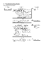
3 Troubleshooting Guide (Refer to Wiring Connection Diagram) 3 - Panasonic EY7460 | Service Manual - Page 4
Q for EY7960 only 4 - Panasonic EY7460 | Service Manual - Page 5
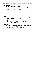
3.1. Trial Operation (after checking Troubleshooting Guide.) 5 - Panasonic EY7460 | Service Manual - Page 6
4 Disassembly and Assembly Instructions 4.1. How to Disassemble Keyless Chuck. Ref. No. 1A Procedure 1A Fig. 1 Removal of the Keyless Drill Chuck. 1. Set the clutch handle to position 1 and select "LOW" position. 2. Turn the lock collar counterclockwise direction to open the chuck jaws. 3. Use a - Panasonic EY7460 | Service Manual - Page 7
4.2. How to Disassemble Main Unit. Ref. No. 2A Procedure 2A Removal of the Housing. 1. Remove the support handle. (See Fig. 4). 2. Remove nine housing screws. (See Fig. 5). NOTE: Grease rubbing part of housing with Shell Alvania for assembly. (See Fig. 6) Fig. 4 Fig. 6 Fig. 5 - Panasonic EY7460 | Service Manual - Page 8
Ref. No. 2C Procedure 2A → 2B → 2C Fig. 8 Fig. 9 Removal or attachment of the Gear Box Block. EY7460 (Removal) 1. Turn the thrust plate to remove. 2. The internal parts of gear box block can be removed one after another. (See Fig. 8) (Attachment) 1. Start from inserting 6 rollers and balls into the - Panasonic EY7460 | Service Manual - Page 9
Ref. No. 2D Procedure 2A → 2B → 2C → 2D Assembly of the Adjusting Screw and the Clutch Handle. 1. Hold the driving block with the click spring on top, and align the smallest projection of adjusting screw with the clutch case. (See Fig. 14) NOTE: Make sure that the adjusting screw has its own - Panasonic EY7460 | Service Manual - Page 10
5 Wiring Connection Diagram 6 Schematic Diagram 10 - Panasonic EY7460 | Service Manual - Page 11
7 Exploded View and Replacement Parts List Model No. : EY7460 Exploded View for EY7460 - Panasonic EY7460 | Service Manual - Page 12
HANDLE SEMS SCREW DC MOTOR SEMS SCREW SWITCH CONTROL PCB OPERATION PANEL TORX TAPPING SCREW GEAR BOX BLOCK SUPPORT HANDLE BATTERY PACK COVER TOOL CASE OPERATING INSTRUCTIONS Q'ty Remarks 1 (for EUROPE), 1 (for OCEANIA), 1 1 1 1 1 2 (K3*6) 1 2 (K5 - Panasonic EY7460 | Service Manual - Page 13
Model No. : EY7960 Exploded View for EY7960 - Panasonic EY7460 | Service Manual - Page 14
HANDLE SEMS SCREW DC MOTOR SEMS SCREW SWITCH CONTROL PCB OPERATION PANEL TORX TAPPING SCREW GEAR BOX BLOCK SUPPORT HANDLE BATTERY PACK COVER TOOL CASE OPERATING INSTRUCTIONS Q'ty Remarks 1 (for EUROPE), 1 (for OCEANIA), 1 1 1 1 2 (K3*6) 1 2 (K5*6)
-
 1
1 -
 2
2 -
 3
3 -
 4
4 -
 5
5 -
 6
6 -
 7
7 -
8
-
9
-
10
-
11
-
12
-
13
-
14
 |
 |

© Panasonic Electric Works Co., Ltd. 2008.
All rights reserved.
Unauthorized copying and distri-
bution is a violation of law.
Order Number PTD0810X45CE
Cordless Drill & Driver
Cordless Hammer Drill & Driver
Model No.
EY7460
EY7960
Europe
Oceania
TABLE OF CONTENTS
PAGE
PAGE
1 Warning
--------------------------------------------------------------
2
2 Specifications
-----------------------------------------------------
2
3 Troubleshooting Guide
-----------------------------------------
3
4 Disassembly and Assembly Instructions
----------------
6
5 Wiring Connection Diagram
---------------------------------
10
6 Schematic Diagram
---------------------------------------------
10
7 Exploded View and Replacement Parts List
-----------
11