Poulan PR240 Owner Manual
Poulan PR240 Manual
 |
View all Poulan PR240 manuals
Add to My Manuals
Save this manual to your list of manuals |
Poulan PR240 manual content summary:
- Poulan PR240 | Owner Manual - Page 1
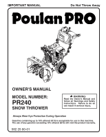
Do Not Throw Away OWNER'S MANUAL MODEL NUMBER: PR240 SNOW THROWER WARNING: Read the Owner's Manual and follow all Warnings and Safety Instructions. Failure to do so can result in serious injury. Always Wear Eye Protection During Operation Gasoline containing up to 10% ethanol (E10) is acceptable - Poulan PR240 | Owner Manual - Page 2
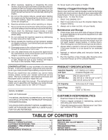
instructions could result in serious injury. Look for this symbol to point out important safety precautions. It means CAUTION!!! BECOME ALERT!!! YOUR SAFETY IS INVOLVED. WARNING: Always disconnect spark plug wire and place it where it cannot contact plug in order to prevent accidental starting parts - Poulan PR240 | Owner Manual - Page 3
Liters) Spark Plug: Gap: F6RTC 0.030" (0,762 mm) CUSTOMER RESPONSIBILITIES • Read and observe the safety rules. • Follow a regular schedule in maintaining, caring for and using your snow thrower. • Follow the instructions under "Maintenance" and "Storage" sections of this owner's manual. TABLE - Poulan PR240 | Owner Manual - Page 4
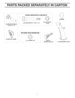
PARTS PACKED SEPARATELY IN CARTON (2) CARRIAGE BOLTS 5/16-18 x 2 1/4" (2) SHEAR BOLTS 1/4-20 x 1-3/4 (2) LOCKNUTS 1/4-20 (2) KNOB (2) HANDLE KNOBS (1) LOCKNUT 3/8 SAFTEY IGNITION KEY (S) 4 - Poulan PR240 | Owner Manual - Page 5
these instructions and this manual in its entirety before you attempt to assemble or operate your new snow thrower. Reading the entire manual will and parts boxes from carton. 2. Cut down all four corners of carton and lay panels flat. 3. Remove the two (2) screws securing the auger housing - Poulan PR240 | Owner Manual - Page 6
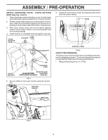
ASSEMBLY / PRE-OPERATION INSTALL DISCHARGE CHUTE / CHUTE ROTATOR HEAD (See Fig. 4 and 5) 1. Place discharge chute assembly on top of chute base with discharge opening toward front of snow thrower. 2. Position chute rotator head over chute bracket. If necessary, rotate chute assembly to align square - Poulan PR240 | Owner Manual - Page 7
. INSERT CHOKE CLOSED TO START AND RUN (START) PRIMER RECOIL START CHOKE OPEN (RUN) IGNITION KEY. PULL OUT TO STOP DANGER DO NOT PLACE HANDS NEAR BLADES DANGER, KEEP FEET AWAY REMOVE SPARK PLUG WIRE BEFORE PERFORMING MAINTENANCE DANGER READ OPERATORS MANUAL WATCH FOR THROWN OBJECTS OPERATE - Poulan PR240 | Owner Manual - Page 8
start button - used for starting the engine. Recoil (auxiliary) starter handle - used for starting engine. Primer - pumps additional fuel from the carburetor to the cylinder for use when starting a cold engine. Choke Control - used for starting . Auger control lever - used to engage auger motion - Poulan PR240 | Owner Manual - Page 9
discharge chute or auger become clogged, shut-off engine and wait for all moving parts to stop. Use position. DISCHARGE CHUTE CONTROL LEVER OFF FUELCONTROL INSTRUCTIONS ON FIG. 8 TO USE CHOKE CONTROL choke control whenever you are starting a cold engine. Do not use to start a warm engine. • - Poulan PR240 | Owner Manual - Page 10
repairing, or inspecting, make certain all controls are disengaged and the auger/impeller and all moving parts have stopped. Disconnect the spark plug wire and keep the wire away from the spark plug to prevent accidental starting. CAUTION: Do not move speed control lever when traction drive control - Poulan PR240 | Owner Manual - Page 11
in storage. To avoid engine problems, the fuel system should be emptied before storage of 30 days or longer. Drain the gas tank, start the engine and let it run until the fuel lines and carburetor are empty. Use fresh fuel next season. See Storage Instructions for additional information. Never use - Poulan PR240 | Owner Manual - Page 12
Engine will not develop full power until it has reached normal operating temperature. WARM START Follow the steps above, keeping the choke in the "OFF" position. DO conditions. See "TO ADJUST SKID PLATES" in this section of this manual. • For extremely heavy snow, reduce the width of snow removal by - Poulan PR240 | Owner Manual - Page 13
as instructed in this manual. Some adjustments will need to be made periodically to properly maintain your snow thrower. All adjustments in the Service and Adjustments section of this manual should be checked at least once each season. • Once a year, you should replace the spark plug and check belts - Poulan PR240 | Owner Manual - Page 14
at the beginning of each season or after every 100 hours of operation, whichever occurs first. Spark plug type and gap setting are shown in the "PRODUCT SPECIFICATIONS" section of this manual. CLEANING IMPORTANT: For best performance, keep snow thrower housing free of any dirt or trash. Clean the - Poulan PR240 | Owner Manual - Page 15
avoid serious injury, before performing any service or adjustments: 1. Be sure the on/off switch is in the OFF position. 2. Remove safety ignition key. 3. Make sure the augers and all moving parts have completely stopped. 4. Disconnect spark plug wire from spark plug and place wire where it cannot - Poulan PR240 | Owner Manual - Page 16
components are moving correctly. Continue with "AFTER REPLACING BELTS" instructions. ENGINE PULLEY AUGER BELT TENSIONER ARM AUGER BELT HANDLE MOUNTING BRACKET FIG. 19 3. REMOVE BELT COVER - See "TO REMOVE BELT COVER" in this section of this manual. 16 FRAME UPPER ASSEMBLY 5/16" BOLT LOWER - Poulan PR240 | Owner Manual - Page 17
FIG. 22 SEE ENGINE MANUAL CARBURETOR Your carburetor is not adjustable. Engine performance should not be affected at altitudes up to 2,134 meters. If your engine does not operate properly due to suspected carburetor problems, take your snow thrower to a service center/department. ENGINE SPEED - Poulan PR240 | Owner Manual - Page 18
the gas tank and carburetor if using fuel stabilizer. ENGINE OIL Drain oil (with engine warm) and replace with clean engine oil. (See "ENGINE" in the Maintenance section of this manual). CYLINDER 1. Remove spark plug. 2. Pour one ounce (29 ml) of oil through spark plug hole into cylinder. 3. Pull - Poulan PR240 | Owner Manual - Page 19
to ON position). 5. Move to FULL position. 6. Prime as instructed in the Operation section of this manual. 7. Wait a few minutes before restarting, DO NOT prime. 8. Connect wire to spark plug. 9. Replace spark plug. 10. Empty fuel tank & carburetor, refill with fresh, clean gasoline. 11. Empty fuel - Poulan PR240 | Owner Manual - Page 20
REPAIR PARTS SNOW THROWER - MODEL PR240 (96192006703) AUGER HOUSING / IMPELLER ASSEMBLY 3 14 14 15 14 10 14 11 13 13 12 13 9 8 6 9 4 8 5 13 2 1 7 7 6 7 05.09.009-J 6 NOTE: All component dimensions given in U.S. inches. 1 - Poulan PR240 | Owner Manual - Page 21
PARTS SNOW THROWER - MODEL PR240 (96192006703) AUGER HOUSING / IMPELLER ASSEMBLY KEY NO. 1 2 3 4 5 6 7 8 9 10 11 12 13 14 15 PART AUGER BELT GUIDE NOTE: All component dimensions given in U.S. inches. 1 inch = 25.4 mm IMPORTANT: Use only Original Equipment Manufacturer (O.E.M.) replacement parts - Poulan PR240 | Owner Manual - Page 22
SNOW THROWER - MODEL PR240 (96192006703) AUGER HOUSING / IMPELLER ASSEMBLY 1 3 5X 2 4 5X 05.09.010-C KEY NO. 1 2 3 4 PART NO. 581 70 83-99 532 40 78-25 872 27 05-05 532 15 53-77 DESCRIPTION AUGER HOUSING SCRAPER BAR CARRIAGE BOLT 5/16-18 X .625 GR5 NUT 5/16-18 1 2 KEY NO. 1 2 PART NO. 532 42 - Poulan PR240 | Owner Manual - Page 23
TOOL SCREW HEX WASHER 13-16 X 5/8 1 2 3 3 05.09.007-A 12 3 KEY PART NO. NO. DESCRIPTION 3 1 532 42 04-78 AUGER BEARING 2 532 41 19-39 BEARING PLUG 3 584 29 94-01 SCREW HI-LO WASHD 5/16-14 X 1.00 2 KEY PART NO. NO. DESCRIPTION 1 532 43 59-51 PLATE SKID PLASTIC HDPE 2 585 80 28 - Poulan PR240 | Owner Manual - Page 24
SNOW THROWER - MODEL PR240 (96192006703) CONTROL PANEL / DISCHARGE CHUTE 2 KEY PART NO. NO. DESCRIPTION 1 588 07 78-03 CHUTE WELDMENT ASSEMBLY ( 25.4 mm IMPORTANT: Use only Original Equipment Manufacturer (O.E.M.) replacement parts. Failure to do so could be hazardous, damage your snow thrower - Poulan PR240 | Owner Manual - Page 25
SNOW THROWER - MODEL PR240 (96192006703) CONTROL PANEL / DISCHARGE CHUTE 1 2 KEY PART NO. NO. DESCRIPTION 1 581 13 12-08 16 X 1.50 2 3 05.07.023-A 2 3 2 3 1 05.07.007-A KEY NO. 1 2 3 PART NO. 581 12 81-04 532 19 41-89 581 92 87-01 DESCRIPTION CONSOLE COVER PPRO NO LIGHT SCREW HI-LO 13 - Poulan PR240 | Owner Manual - Page 26
PARTS SNOW THROWER - MODEL PR240 (96192006703) CONTROL PANEL / DISCHARGE CHUTE 84 9 7 3 3 10 6 10 1 58 9 6 2 7 05.08.012-A KEY NO. 1 2 3 4 5 6 7 8 9 10 PART ROTATOR BOLT SHOULDER 1/4-20 SPRING COMPRESSION NUT FL LOCK 1/4-20 BRACE SUPPORT SPEED WASHER .625 X .375 X .094 NYLON 6/6 NOTE: - Poulan PR240 | Owner Manual - Page 27
PR240 (96192006703) CONTROL PANEL / DISCHARGE CHUTE 6 8 1 37 4 2 4 5 05.08.011-B KEY NO. 1 2 3 4 5 6 7 8 PART NO. 588 11 37-02 588 11 38-01 588 12 23-01 532 19 79-91 532 42 81-24 581 32 94-01 532 42 33-03 585 80 83-01 DESCRIPTION CABLE CONTROL DRIVE CABLE CONTROL AUGER - Poulan PR240 | Owner Manual - Page 28
PARTS SNOW THROWER - MODEL PR240 (96192006703) CONTROL PANEL / DISCHARGE CHUTE 1 5 5 05.08.010-A 2 5 4 KEY NO. 1 2 3 4 5 6 7 PART inch = 25.4 mm IMPORTANT: Use only Original Equipment Manufacturer (O.E.M.) replacement parts. Failure to do so could be hazardous, damage your snow thrower and - Poulan PR240 | Owner Manual - Page 29
HEAD WITH PATCH 3 05.06.001-G 1 2 4 3 2 4 05.05.001-E KEY NO. 1 2 3 4 PART NO. 588 67 21-02 817 00 06-12 581 62 20-02 817 00 05-10 DESCRIPTION LOWER HANDLE SCREW HEX WASH HD 3/8-16 X .75 CHUTE ROTATOR SUPPORT ASM BOLT HEX 5/16-18 NOTE: All component dimensions given in - Poulan PR240 | Owner Manual - Page 30
SNOW THROWER - MODEL PR240 (96192006703) 3 4 12 6 5 2 6 10 11 9 7 8 12 13 14 15 16 18 13 12 19 17 13 20 05.02.001-G NOTE: All component dimensions given in U.S. inches. 1 inch = 25.4 mm IMPORTANT: Use only Original Equipment Manufacturer (O.E.M.) replacement parts. Failure to do - Poulan PR240 | Owner Manual - Page 31
SNOW THROWER - MODEL PR240 (96192006703) KEY NO. 1 2 3 4 5 6 7 8 9 10 11 12 13 14 15 16 17 18 19 20 PART NO. 585 69 15-01 inch = 25.4 mm IMPORTANT: Use only Original Equipment Manufacturer (O.E.M.) replacement parts. Failure to do so could be hazardous, damage your snow thrower and void your - Poulan PR240 | Owner Manual - Page 32
SNOW THROWER - MODEL PR240 (96192006703) 6 1 2 6 4 3 2 1 8 7 3 5 5 3 05.03.001-B KEY NO. 1 2 3 4 5 6 7 8 PART NO. 532 44 1 inch = 25.4 mm IMPORTANT: Use only Original Equipment Manufacturer (O.E.M.) replacement parts. Failure to do so could be hazardous, damage your snow thrower and void - Poulan PR240 | Owner Manual - Page 33
PARTS SNOW THROWER - MODEL PR240 (96192006703) CHASSIS / ENGINE / PULLEYS 5 5 7 8 55 3 54 6 6 6 65 05.01.007-C 2 22 2 6 6 5 6 1 6 5 KEY NO. - - 1 2 3 4 5 6 7 8 PART CLIP WASHER .343 X .750 X 16GA BLACK KEY NO. 1 PART NO. DESCRIPTION 583 94 05-02 SMALL MOUNTING PLATE 1 05.01.002 - Poulan PR240 | Owner Manual - Page 34
SNOW THROWER - MODEL PR240 (96192006703) CHASSIS / ENGINE / PULLEYS 3 2 2 1 4 4 05.04.002-B KEY NO. 1 2 3 4 PART NO. 587 10 54-01 532 14 50-06 DESCRIPTION BELT COVER BLACK ASSEMBLY (INCLUDES 2 & 4) BOLT HEX WSH THDRL 1/4-20 X 1 CABLE GUIDE PALNUT 1/4 IN NOTE: All component dimensions - Poulan PR240 | Owner Manual - Page 35
PARTS SNOW THROWER - MODEL PR240 (96192006703) CHASSIS / ENGINE / PULLEYS 1 2 3 4 2 34 6 7 20 5 11 9 10 6 7 8 15 12 13 10 6 14 16 19 18 17 05.04.001-K KEY NO. 1 2 3 4 5 6 7 8 9 10 PART 5/16-18 X .875 DRIVE BELT 4L X 38.2 IMPELLER BELT IDLER PULLEY 2.0 FLANGELESS W/SPACER NOTE - Poulan PR240 | Owner Manual - Page 36
2 1 SNOW THROWER - MODEL PR240 (96192006703) KEY NO. 1 2 PART NO. 580 62 77-03 580 62 76-03 DESCRIPTION . 1 inch = 25.4 mm IMPORTANT: Use only Original Equipment Manufacturer (O.E.M.) replacement parts. Failure to do so could be hazardous, damage your snow thrower and void your warranty. 36 - Poulan PR240 | Owner Manual - Page 37
PARTS BAG OF PARTS 6 5 4 SNOW THROWER - MODEL PR240 (96192006703) 3 1 2 05.18.007-A KEY NO. 1 2 3 4 5 6 PART 25 CONCAVE KNOB 5/16-18TWO-WING KNOB SOFT TOUCH SLOTTED 1 01.14.009-B KEY NO. 1 PART NO. 532 44 30-59 DESCRIPTION SAFETY IGNITION KEY KIT NOTE: All component dimensions given in U.S. - Poulan PR240 | Owner Manual - Page 38
DECALS SNOW THROWER - MODEL PR240 (96192006703) KEY PART NO. NO. DESCRIPTION 1 1 532 18 40-45 DECAL AUGER 4 2 532 19 96-82 DECAL CHUTE 3 532 19 96-83 DECAL AUGER SAFETY 4 532 18 40-28 DECAL BELT GUIDE 3 2 05.16.001-A NOTE: All component dimensions given in U.S. inches. 1 inch = 25 - Poulan PR240 | Owner Manual - Page 39
- MODEL PR240 (96192006703) 5 5 3 1 KEY PART NO. NO. 1 532 19 96-83 3 532 19 96-82 4 532 18 40-45 5 532 18 40-28 - - 582 25 80-01 - - 582 25 80-03 - - 582 25 80-02 DESCRIPTION DECAL, DANGER DECAL, DANGER, DEFLECTOR DECAL, DANGER DECAL, BELT GUARD OWNER'S MANUAL, ENGLISH OWNER'S MANUAL, FRENCH - Poulan PR240 | Owner Manual - Page 40
- MANUAL START (208CC) 9 532 42 05-86 COOLLNG FAN - FLYWHEEL (PLASTIC - 208CC) 10 587 17 61-01 CRANKSHAFT (#18 KEYED 179CC SNOW) KEY PART NO. CARBURETOR (L10-1) (GEN II SNOW 179CC- W/GSKTS & SPACER) 18 532 42 49-55 IGNITION COIL (CDI) (179CC) (STANDARD) 19 N/A N/A 20 532 42 49-39 SPARK PLUG - Poulan PR240 | Owner Manual - Page 41
PR240 (96192006703) COMPLETE ENGINE-585742603 KEY PART SEAL KIT (2 PCS FOR 3/4- INCH CRANKSHAFT) 34 532 43 69-66 SPARK PLUG BOOT - WITH METAL SHIELD (SNOW) 35 N/A N/A 36 587 17 2) 69 532 42 49-51 CARBURETOR STUDS & COUPLLNG KIT-SNOW 70 580 35 36-01 CARBURETOR REPAIR KIT (136/208/254CC) - Poulan PR240 | Owner Manual - Page 42
SERVICE NOTES 42 - Poulan PR240 | Owner Manual - Page 43
SERVICE NOTES 43 - Poulan PR240 | Owner Manual - Page 44
05.03.16 TH Printed in U.S.A.
-
 1
1 -
 2
2 -
 3
3 -
 4
4 -
 5
5 -
 6
6 -
 7
7 -
8
-
9
-
10
-
11
-
12
-
13
-
14
-
15
-
16
-
17
-
18
-
19
-
20
-
21
-
22
-
23
-
24
-
25
-
26
-
27
-
28
-
29
-
30
-
31
-
32
-
33
-
34
-
35
-
36
-
37
-
38
-
39
-
40
-
41
-
42
-
43
-
44
 |
 |

OWNER'S MANUAL
MODEL NUMBER:
PR240
SNOW THROWER
Always Wear Eye Protection During Operation
IMPORTANT MANUAL
Do Not Throw Away
WARNING:
Read the Owner's Manual and
follow all Warnings and Safety
Instructions.
Failure to do so
can result in serious injury.
582 25 80-01
Gasoline containing up to 10% ethanol (E10) is acceptable for use in this machine.
The use of any gasoline exceeding 10% ethanol (E10) will void the product warranty.