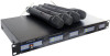
Pyle PDWM5000 PDWM5000 Manual 1
Pyle PDWM5000 Manual
 |
View all Pyle PDWM5000 manuals
Add to My Manuals
Save this manual to your list of manuals |
Pyle PDWM5000 manual content summary:
- Pyle PDWM5000 | PDWM5000 Manual 1 - Page 1
MANUAL PDWM5000 PROFESSIONAL SERIES WIRELESS MICROPHONE SYSTEM ...........PREFACE........... Thank you for buying our excellent wireless microphone signals). 2) Open the battery cover of microphone and install the batteries inside the compartment properly, then replace the cover. 3) Position - Pyle PDWM5000 | PDWM5000 Manual 1 - Page 2
UP DOWN UP CHA CHA DOWN UP POWER 2 3 4 5 6 1 3 4 6 7 PWMA2000 PROFESSIONAL WIRELESS MICROPHONE SYSTEM POWER 2 1 CHA VOLUME 3 POWER 2 CHA VOLUME CHB VOLUME CHC VOLUME 4 4 PWMA2000 PROFESSIONAL WIRELESS MICROPHONE SYSTEM 8 10 CHD VOLUME 9 REAR PANEL OF RECEIVER 17 12
-
 1
1 -
 2
2
 |
 |

R
PDWM5000
OWNER S MANUAL
PROFESSIONAL SERIES WIRELESS MICROPHONE SYSTEM
R
PyleAudio.com
718.535.1800
718.236.2400 (fax)
1600 63rd Street, Brooklyn NY
11204
.........
SPECIFICATION
.........
1) Frequency Range:
....................
VHF 160-280MHz
2) Frequency Stability:
........................
0.005%
3) Modulation mode:
..........................
VHF
4) Modulation Deviation:
.......................
20KHz
5) Audio Frequency Response:
...................
40Hz-20KHz
6) SignaltoNoise Ratio:
........................
>60dB
7) Maximum Sound Pressure Level:
..................
>100dB
8) Distortion:
..............................
0.5%
9) Operating Range:
................
80m (under typical conditions)
10) Operation Temperature Range:
.................
10.~+50.
System Specitications
1) RF Output Power:
........
100mW MAX
2) Harmonic Suppression:
........................
40dB
3) Antenna:
..............................
Builtin
4) Power Requirement:
........................
9V Battery
5) Nominal Current Drain:
..................
Approximately 15mA
6) Battery Life:
............................
12 hours
................
Transmitter
1) Receive Mode:
....................
Crystal Frequency Lock
2) Sensitiity:
.........................
40dBu(S/N=60dB)
3) SignaltoNoise Ratio:
.........................
>60dB
4) Audio Output Level:
....................
0~400mV Max
5) Power Supply:
.....................
AC110V/220V(.10%)
6) Dimension:
.....................
WxDxH=485x240x52mm
Transmitter
-4-
Thank you for buying our excellent wireless microphone series
products.
Before you use our products, please read this Owner's
manual for vour corrective operation, Please keep this manual in a safety place for your future reference.
VHF
series
professional
wireless
microphone systems introducesa number of advanced techniques and components, including
the
efficient
lowconsumption
RF transmission,
impact elimination,
slowcontrolled output,
superiorssensitivity
VHF narrowband
HF
and
MF filters and
15ppm
Crystal
Frequency
Lock
etc. Online simulation
EDA
and strict
quality control
are
applied
to
ensure
each system withexcellent function.
Introducing a special ALC circuit to ensure nondistortion;
lntroducing frequency compressingexpanding technique to lower the
noise and enlarge the dynamic range.
Superior squelch and high signaltonoise ratio.
Aimost zero noise output when standby.
Broad frequency response range, super low distortion.
Perfect operation status indications.
1) Plug
the provided audio cable into
the receiver's
ALL output connector,
and the other end
into a
mixer or power amplifier system.
Extend the two
antennas fully to the vertical
position.Switch on
the receiver, the POWER ON light will glow indicating
the machine
standby. (Better
keep distances between
the receiver and floor to ensure
good receiving
signals).
2) Open the
battery cover of microphone
and install
the
batteries
inside the compartment
properly, then
replace
the cover.
3) Position the
transmitter power
switch to ON, indicator light
will glow (wid
position is MUTE ).
Now the receiver's
corresponding
.
channel
light
will also
glow, indicating that the
receiver has already
received the effective
signals from the transmitter.
Adjust the
volume knobs of the receiver and power amplifier to ensure the suitable volume for the
system. Speak with microphone to check the sound.
4) When
the transmitter power indicator
dardens, it indicates low
battery power. Please
change with new batterles
in time. (Note to not
mix new
and old batteries together)
5) When using multiple
systems at the
same time, it
is necessary to use machines of different frequency.
System Tumon Process: Receiver .Mixer or Pre Amplifier .Power Amplifier (Opposite
when Tumoff)
-1-
...........
PREFACE
...........
FEATURES:
SYSTEM SETUP
Introducing multiple HF and MF narrowband filters to eliminate
interfering signal.
Introducing low power consumption components to ensure the longer
battery life.
Special impact wave eliminating circuit for handheld microphone switches.
Long practical distance. Over 80m in ideal circumstances; practiacal
20m radius incomplex circumstances;
Multiple frequency design. Be able to use two microphones at the
same time withoutmutual interference;
Applicable for medium & small stages, karaoke halls, and home
entertainment etc.