Pyle SLPPTB22 Instruction Manual
Pyle SLPPTB22 Manual
 |
View all Pyle SLPPTB22 manuals
Add to My Manuals
Save this manual to your list of manuals |
Pyle SLPPTB22 manual content summary:
- Pyle SLPPTB22 | Instruction Manual - Page 1
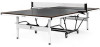
SLPPTB22 Durable Indoor Table Tennis Table Designed with MDF Table Top for Optimal Bounce - Pyle SLPPTB22 | Instruction Manual - Page 2
IMPORTANT SAFETY NOTICE For your safety and bene t, read this manual carefully before starting assembly and using this product. Failure to follow the instructions and safety precautions in this manual can result in serious injury or damage to equipment. SAFETY INFORMATION: • DO NOT allow children - Pyle SLPPTB22 | Instruction Manual - Page 3
PCS P4 P5 P2 Caster Beams 2.PCS P3 Middle Plate 1.PCS P6 Support Tube 4.PCS P7 Strut Tube 4.PCS P8 Accessory Holder 3.PCS Net H17 H18 3.0x12MM Screw 4.PCS H19 Stop Spool 8.PCS Triangle Support Plates 4.PCS Bolt M10x110MM 4.PCS Bolt M10x75MM 8.PCS Bolt M8x90MM 4.PCS M6x15mm - Pyle SLPPTB22 | Instruction Manual - Page 4
line up holes. Thread the bolt in the following order: Bolt (H2) through a Washer (H13), the Caster Beam (P2), a Stop Spool (H17), the Triangle Support Plate (H18), another Washer (H13), and Lock Nut (H6). • Hand tighten only. DO NOT tighten completely, as nuts/bolts will be adjusted in a later step - Pyle SLPPTB22 | Instruction Manual - Page 5
STEP 2 Hardware Needed: H4 Bolt M8x60MM 4.PCS H7 M8 Lock nut 4.PCS H14 M8 Washer 8.PCS P2 Caster Beams 2.PCS P3 M10 Lock nut 8.PCS • Attach Middle Plate (P3) to Caster Beams (P2) as shown in the above image. • Thread the Bolt (H4) through the Washer (H14), both Steel Frames, another Washer (H14) - Pyle SLPPTB22 | Instruction Manual - Page 6
: DO NOT overtighten the nuts, as this will apply too much pressure to the spacers and may cause them to crack. IMPORTANT NOTE: • The Gray Support Tube should have the longer end attached to the Caster Beam, bending up and out. • The Black Strut Tube should have the longer end attached - Pyle SLPPTB22 | Instruction Manual - Page 7
area, posing a potential tripping hazard. Exercise caution when completing the remaining assembly steps. • Place the Strut Tubes (P5) in a upward position and lay the Gray Support Tubes (P4) down in front to avoid interference while attaching the Table Top. www.SereneLifeHome.com 7 - Pyle SLPPTB22 | Instruction Manual - Page 8
TIP: if there are three (3) assemblers, have two lift the table with one guiding the table onto the tubes. WARNING: • At least (2) to three (3) adults holes on the U-Beam line up with the pre-drilled holes on the Black Support Beam. This is important for a later step. • Continue on to next step - Pyle SLPPTB22 | Instruction Manual - Page 9
will apply too much pressure to the spacers and may cause them to crack. WARNING: • DO NOT open the table to playing position until all support beams and hinges are attached to table frame. • DO NOT leave table unattented in the upright position. Table is not secure yet and can be - Pyle SLPPTB22 | Instruction Manual - Page 10
STEP 7 Hardware Needed: H16 3.0x12MM Screw 4.PCS WARNING: • DO NOT open the table to playing position until all support beams and hinges are attached to table frame. • DO NOT leave table unattented in the upright position. Table is not secure yet and can be - Pyle SLPPTB22 | Instruction Manual - Page 11
4.PCS H12 M6 Plastic Spacer 4.PCS H15 M6 Washer 8.PCS P5 Strut Tube 4.PCS WARNING: • DO NOT open the table to playing position until all support beams and hinges are attached to table frame. • DO NOT leave table unattented in the upright position. Table is not secure yet and can be - Pyle SLPPTB22 | Instruction Manual - Page 12
STEP 9 Hardware Needed: P6 Accessory Holder 3.PCS H8 M6 Lock nut 2.PCS H16 M6x15mm Phillips Head Machine Bolt 2.PCS P6 H19 H19 H8 Accessory Holder • Assemble Accessory Holder by positioning one of the plastic pieces over one of the pre-drilled holes on the H frame. • Screw into the frame with a - Pyle SLPPTB22 | Instruction Manual - Page 13
table partially opened or not fully secure. • Before moving on to the next steps, ensure all support tubes and hinges are assembled correctly and appropriately. • DO NOT grasp metal legs, support pieces, linkage, or hinges. These parts can move and entrapment and/or pinching of fingers or hands - Pyle SLPPTB22 | Instruction Manual - Page 14
Putting the Table Play-Back and Play Mode • After correctly assembling both Table Tops, your table can safely be moved from storage mode (Figure 1) to the play-back (Figure 3) or normal (Figure 4) play position. • Grab the center of the top edge with both hands. WITH CAUTION, gently pull the table - Pyle SLPPTB22 | Instruction Manual - Page 15
STEP 11 Hardware Needed: P7 Net Clipper 2.PCS P8 Net 1.PCS • Now that your table is in play position, you are ready to assemble the net. • Secure the Net Clipper (P7) to your Table Top (P1) by clipping it near the center of the two Table Tops. NOTE: If you plan on putting the Table in storage mode, - Pyle SLPPTB22 | Instruction Manual - Page 16
• Leg Levelers and Bumper Corners for Stability and Protection What's in the Box: • Table tennis table • Net and clip set • Instruction book Technical Specs: • Wheel diameter: 3" -inches • Construction Material: MDF+STEEL • Table Top Thickness: 7/10'' -inches • Lockable Casters Length: 3'' -inches - Pyle SLPPTB22 | Instruction Manual - Page 17
www.SereneLifeHome.com 17 - Pyle SLPPTB22 | Instruction Manual - Page 18
Questions? Issues? We are here to help! Phone: (1) 718-535-1800 Email: [email protected]
-
 1
1 -
 2
2 -
 3
3 -
 4
4 -
 5
5 -
 6
6 -
 7
7 -
8
-
9
-
10
-
11
-
12
-
13
-
14
-
15
-
16
-
17
-
18
 |
 |

Durable Indoor Table Tennis Table
SLPPTB22
Designed with MDF Table Top for Optimal Bounce