Rheem P-M336 Operating Instructions
Rheem P-M336 Manual
 |
View all Rheem P-M336 manuals
Add to My Manuals
Save this manual to your list of manuals |
Rheem P-M336 manual content summary:
- Rheem P-M336 | Operating Instructions - Page 1
sup- plier's instructions. • If you cannot reach your gas supplier, call the fire department. Installation and service must be performed by a qualified installer, service agency or the gas supplier. This manual should be maintained in legible condition and kept adjacent to the heater or in a safe - Rheem P-M336 | Operating Instructions - Page 2
guide for high as 6000 ppm. • Occasional chemical shock dosing of the pool or spa water should not damage the heater controlled, they can lead to excessive chlorine level which can damage your heater instructions on page 2, Automatic Chlorinator instructions on page 8, Hurricane Tie-Down instructions - Rheem P-M336 | Operating Instructions - Page 3
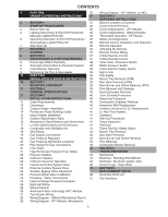
Water Pressure Switch 9 Cold Weather Operation 38 Flame Roll-Out Safety Switch 9 Winterizing the Pool & Spa Heater 38 High Limits 10 PART TWO 39 Pilot Safety INSTALLATION & SERVICE INSTRUCTIONS 39 Burner Tray Removal (ATM) 10 SECTION 1 39 Gas Valve Removal (ATM) RECEIVING EQUIPMENT 39 - Rheem P-M336 | Operating Instructions - Page 4
, are also available. This manual provides installation, operation, maintenance, and service information for these heaters. ON OFF If your heater has been installed correctly, operating the heater is an easy task. The upper front panel of the heater contains the control center that allows you to - Rheem P-M336 | Operating Instructions - Page 5
in a fire or explosion. D. Do not use this appliance if any part has been under water. Immediately call a qualified service technician to inspect the appliance and to replace any part of the control system and any gas control which has been under water. LIGHTING INSTRUCTIONS 1. STOP! Read the - Rheem P-M336 | Operating Instructions - Page 6
heaters. OPERATING INSTRUCTIONS explosion. D. Do not use this appliance if any part has been under water. Immediately call a qualified service technician to inspect the appliance and to replace any part of the control system and any gas control which has been under water. OPERATING INSTRUCTIONS - Rheem P-M336 | Operating Instructions - Page 7
off the manual gas control to the heater. VISUAL INSPECTION - ATMOSPHERIC HEATERS With the heater on, remove service person at the time of installation and periodically checked thereafter. Refer to Pressure Switch Adjustment on pg. 38 of this manual problems, diabetes, or blood pressure problems - Rheem P-M336 | Operating Instructions - Page 8
burner of dust and lint. 3. Inspect and operate all controls, gas valve and pressure relief valve (if equipped). 4. Make high gas pressure. Low flame means low gas pressure. Should the latter occur, shut the heater off and contact your gas supplier or qualified service agency. 5. On indoor heaters - Rheem P-M336 | Operating Instructions - Page 9
in freezing climate areas may be shut down for the winter. Observe the following procedure for winterizing the heater: 1. Turn off gas valve, manual gas valve, and electrical supply to the heater. 2. Open drain plug located on the inlet/outlet header, (under water pipes). Remove the heat exchanger - Rheem P-M336 | Operating Instructions - Page 10
SERVICE INSTRUCTIONS SECTION 1 - RECEIVING EQUIPMENT The manufacturer recommends that this manual be reviewed thoroughly before installing your pool/spa heater. If there are any questions that this manual Lading when signing for the equipment. Remove the heater from the carton. If it is damaged, - Rheem P-M336 | Operating Instructions - Page 11
repairs according to these instructions. WARNING: Improper installation, adjustment, alteration, service or maintenance may damage the equipment, create a hazard resulting in asphyxiation, explosion or fire, and will void the warranty. CODE REQUIREMENTS NOTE: The heater should not be located - Rheem P-M336 | Operating Instructions - Page 12
must be installed in a manner that will enable the heater to be serviced without removing any structure around the heater. FLOORING: This heater can be installed on combustible flooring. OUTDOOR HEATER INSTALLATION These heaters are design-certified for outdoor installation, when equipped with the - Rheem P-M336 | Operating Instructions - Page 13
be at least 3 ft above any forced air inlet, or intake ducts located within 10 ft horizontally. For installations in Canada, pool heaters shall not be installed with the top of the vent assembly within 10 ft below, or to either side, of any opening into the building. - Rheem P-M336 | Operating Instructions - Page 14
FLORIDA AND TEXAS BUILDING CODES WIND SPEED = 150 MPH, 3 SECOND GUST EXPOSURE = C 206/266/336/406 Atmospheric MODEL # B 206 20" B 266 23" 336 26" 406 29" 40" 2" x 6" x 1/8" Pallet Anchor Bracket (4 Total) (Kit# 011636) 28" 3" Min. Conc. Pad by others 1/4" x 1-3/4" S.S. Tapcon Bolt & - Rheem P-M336 | Operating Instructions - Page 15
equipment and do not come standard with the heater. OUTDOOR STACK KIT INCLUDES: (1) Drafthood, painted (1) Adapter plate (3) Mounting brackets (clips) (1) Top panel cover (2) 1-foot sections of metal tape (3) Screws (1) Instructions Clips INDOOR STACK KIT INCLUDES: (1) Drafthood, unpainted - Rheem P-M336 | Operating Instructions - Page 16
" 9" 64-9/16" 14.5" 12-1/8" 3/4" 2" 249 268 21 Designation for an AFT heater using propane gas is "EP"; an AFT heater using natural gas is "EN". Designation for a Millivolt heater using propane gas is "MP"; a Millivolt heater using natural gas is "MN". Prefix "C" is for cast iron (ASME) headers - Rheem P-M336 | Operating Instructions - Page 17
R337A 332.5 26" 8" 57" 13.0" 10-5/8" 3/4" 2" 219 238 19 R407A 399.0 29" 9" 58-1/2" 14.5" 12-1/8" 3/4" 2" 237 256 21 Designation for an AFT heater using natural gas is "EN". Prefix "C" is for cast iron (ASME) headers; "P" is for plastic (polymer) headers. Suffix "X" is for cupro-nickel - Rheem P-M336 | Operating Instructions - Page 18
can damage the heater and void the warranty. VENT PIPING WARNING: Indoor heaters require a in. per ft rise and should be supported at not more than five foot intervals. Plumbers tape, Vent For more information consult the D-2 Power Vent manual, (Catalog No. 6000.57.1). The power vent - Rheem P-M336 | Operating Instructions - Page 19
must not rest on heater drafthood. Support must be provided in compliance with applicable codes. The heater top and drafthood must MIN DRAFT HOOD HEATER Gas piping must have a sediment trap ahead of the heater gas controls, and a manual shut-off valve located outside the heater jacket. All - Rheem P-M336 | Operating Instructions - Page 20
). ELECTRONIC IGNITION GAS VALVES-CONTINUED Gas Pressure Adjustment Robertshaw 7200 (Heater Model 206) Robertshaw 7000 BDER (Heater Models 266-336) MANUAL SHUT-OFF VALVE UNION Gas Pressure Adjustment Robertshaw 7000 DERHC (Heater Model 406) Non-Adjustable Gas Valve MANOMETER GAS PRESSURE TEST - Rheem P-M336 | Operating Instructions - Page 21
FLOW RATES MODEL 206/207 266/267 336/337 406/407 PIPE SIZE 1-1/4"-1-1/2" - 2" 1-1/4"-1-1/2" - 2" 1-1/4"-1-1/2" - 2" 1-1/4"-1-1/2" - 2" MIN. GPM 20 25 35 40 MAX. GPM* 125 125 125 125 *When flow rates exceed maximum GPM an external auxiliary bypass valve is required. See external bypass valve - Rheem P-M336 | Operating Instructions - Page 22
valve (or valves) also be installed in the system. CAST IRON HEADERS (ASME MODELS) Flange Gasket Heater must be located so that any water leaks will not damage the structure of adjacent area. High temperature 2" plastic pipe (CPVC) may be threaded directly into the header flanges. This is not the - Rheem P-M336 | Operating Instructions - Page 23
should be used when flow rates exceed 125 GPM. Usually a high-performance pump size larger than two horsepower will exceed this flow clean filter, adjustment is made by feeling the inlet and outlet pipes at the heater. Outlet pipes should be slightly warmer than inlet and comfortable to the touch. If - Rheem P-M336 | Operating Instructions - Page 24
it to act as the primary heat source. If the primary system provides adequate heat to maintain set-point, the heater will not fire. Be advised that the control panel will then display sensed water temperatures downstream of the primary heating system, rather than the temperature of the water exiting - Rheem P-M336 | Operating Instructions - Page 25
well (Figure 4). Re-route the sensor bulb to the left side of the heater. 5. Remove (12) bolts holding the inlet/outlet and return headers to the Do not over tighten. Torque should not exceed 7 ft/lb. 6. Reconnect high limit, AGS, and pressure switch wires. 7. AFT Models: Insert the temperature - Rheem P-M336 | Operating Instructions - Page 26
. NOTE: See page 38 for further instructions if using a time clock/fireman's switch. OPTION LOCATION LEFT SIDE FIELD WIRING CONTROL BOX (FACTORY MOUNTED LOCATION) The standard field-wiring connection is on the right side of the heater. To wire the heater from the left side, follow these steps - Rheem P-M336 | Operating Instructions - Page 27
transformer and PC board may result. Such damages are not covered under manufacturer's limited warranty. NOTE: Input power to the heater (120 or 240 that full-time power be supplied to the heater from the GFCI power source, and that the heater be controlled by the fireman's switch connection or using - Rheem P-M336 | Operating Instructions - Page 28
WIRING DIAGRAM - MILLIVOLT (MECHANICAL THERMOSTAT) 28 - Rheem P-M336 | Operating Instructions - Page 29
WIRING DIAGRAM - ATMOSPHERIC 29 - Rheem P-M336 | Operating Instructions - Page 30
WIRING DIAGRAM - LO NOx 30 - Rheem P-M336 | Operating Instructions - Page 31
SECTION 4 - SERVICING INSTRUCTIONS GENERAL LOCATION OF CONTROLS ATMOSPHERIC Drain Plug (Located in rear header) AFT Thermostat Circuit Board Roll-Out Switch Gas Valve Pilot LO NOx Drain Plug (Located in rear header) Blower Hose AFT Thermostat Circuit Board Roll-Out Switch (Manual) Blower Gas - Rheem P-M336 | Operating Instructions - Page 32
REMOVAL 1. Remove screw from front door. Set aside door for serviceability. CONTROL ADJUSTMENTS - MILLIVOLT MODELS The water temperature is controlled by the heater thermostat on the upper front panel of the heater. The control center contains an On/Off switch and one thermostat. KNURLED SCREW - Rheem P-M336 | Operating Instructions - Page 33
temperature. A manual power switch provided below the touchpad turns the control power ON or OFF. Program button the pilot flame current using a bar graph and numerical display. A signal of less than 4 indicates a weak flame signal and may require service. Refer to Section 5 - Troubleshooting for - Rheem P-M336 | Operating Instructions - Page 34
in the sequence listed below: Resets board to factory default settings. Resets faults in control can be set for a maximum of 107°F. Control Lockout The heater is equipped with a Control Lockout feature to prevent unauthorized tampering or adjustment of the control settings. To lock out the controls - Rheem P-M336 | Operating Instructions - Page 35
heater (Lo NOx tab is intact). Internal Fault Board fault, replace board. EEPROM Fault Clock/ Fireman Sw Low Temp Lockout Memory fault, reset set points, replace board field switch #1 open. Hi Limit 1 Fault High limit 1 open. Hi Limit 2 Fault High limit 2 open. Rollout Sw Open Rollout switch - Rheem P-M336 | Operating Instructions - Page 36
controlling the heater by displaying Remote in the display. When connecting the heater to a remote system, identify whether it is a two- or three-wire remote system. Select the appropriate instruction with the wiring or circuit board. When one walks to the heater area, an electrostatic charge - Rheem P-M336 | Operating Instructions - Page 37
instructions. NOTE: The remote wires must be connected to the 7-pin connector before the connector is plugged into the board. 2-Wire Remote Control to the heater. To activate the remote control, see page 36. 3-Wire Remote Control Using Three-Position Switch (Pool-Off-Spa, or Low-Off-High) This - Rheem P-M336 | Operating Instructions - Page 38
manual toggle switch and the gas valve. For AFT heaters the fireman's switch connection is located on the 14-pin header connected to the digital control board restriction in the heat exchanger flue passage. HIGH LIMITS The heater is equipped with two automatic high limits. Both are located in the - Rheem P-M336 | Operating Instructions - Page 39
of an internal heat exchanger problem, e.g. scale build-up, defective bypass. Refer to Troubleshooting section (starting on page 43). HIGH LIMIT REMOVAL 1. Shut off main electrical power switch to heater. 2. Remove inlet/outlet inspection panel. 3. Remove defective high limit and replace with a new - Rheem P-M336 | Operating Instructions - Page 40
regular inspection schedule, the frequency depending on the local water conditions and the severity of service. Do not let the tubes clog up solidly. Clean out deposits over 1/16" in thickness. The heater may be cleaned from the return header side, without breaking pipe connections. It is preferable - Rheem P-M336 | Operating Instructions - Page 41
. FLAME ROLL-OUT SAFETY SWITCH Lo NOx heaters are equipped with a thermal cut-off device to prevent flame roll-out in the event the heat exchanger becomes blocked. It is a "manual reset" type roll-out switch that must be reset by a service technician after any over-temperature conditions have been - Rheem P-M336 | Operating Instructions - Page 42
box to the burner tray, and (1) screw that secures the anti-rotation bracket to the heater. 6. Disconnect wires that terminate at gas valve. 7. Unscrew (4) screws that secure the control box. 8. Disconnect pilot wire from the pilot assembly. 9. Disconnect wire connector from the combustion blower - Rheem P-M336 | Operating Instructions - Page 43
SECTION 5 - TROUBLESHOOTING MECHANICAL IMPORTANT NOTICE These instructions are intended for the use of qualified personnel who are specifically trained and experienced in the installation of this type of heating equipment and related system components. Installation and service personnel may be - Rheem P-M336 | Operating Instructions - Page 44
HEATER ELECTRICAL CHECK WITH MILLIVOLT GAS VALVE CAUTION: For qualified service personnel only. 1. Filter must be on with adequate water flow through heater stays on Problem is a high limit and remove jumper Replace high limit that caused heater (200mV± 100) Control/Limit circuit closed (All switches - Rheem P-M336 | Operating Instructions - Page 45
To reset, interrupt power to heater. START TURN GAS SUPPLY OFF. TURN THERMOSTAT (CONTROLLER) TO CALL FOR HEAT POWER TO PC BOARD? NO (24 V NOMINAL) YES SPARK ACROSS IGNITER/SENSOR GAP? NO YES TURN GAS SUPPLY ON PILOT BURNER LIGHTS? NO YES NOTE: Before troubleshooting, familiarize yourself with the - Rheem P-M336 | Operating Instructions - Page 46
wire connections) • Check for 24 volts to Circuit Board (P6 connector) "Remote" and Water Temperature displayed (a remote control is controlling the heater) Note: Disconnect the remote by turning the remote function off. See page 36 for instructions. NO Is a fault code displayed and flashing? YES - Rheem P-M336 | Operating Instructions - Page 47
be issued. Any part returned for replacement under standard company warranties must be properly tagged with a return parts tag, completely filled in with the heater serial number, model number, etc., and shipped to the Company freight prepaid. MANUFACTURER: 2151 EASTMAN AVENUE OXNARD, CA 93030 47 - Rheem P-M336 | Operating Instructions - Page 48
ATMOSPHERIC HEATERS 3-V I-S 14-M I3-S 1-V 4-V 6-HP 2-V 8-C 8-S 11-S 10-M 9-M 5-C 3-M 7-C 4-C I5-HM 3-HP 7-HP 4-HP 3-R 6-S 14-M 4-S 17-HM 2-M 4-M 13-M 3-S 12-M 11-M 2-J 1-G 2-B 5-M 10-S 1-B 3-B 5-B 4-B 2-S 5-HP 7-HP 6-HP I2-S 7-S 2-R 4-S 5-S 16-M 1-R 16-M 1-J 48 - Rheem P-M336 | Operating Instructions - Page 49
LO NOx HEATERS 3-V I-S 9-M I3-S 1-V 4-V 2-S 2-V 6-HP 5-HP 8-C 11-S 8-S 5-C 4-C 6-M 2-J I5-HM 3-HP 3-R 4-HP 9-M 6-S 4-S 17-HM 3-J 8-M 3-S 7-M 3-B 1-G 4-B 2-M 2-B 7-C 5-B 1-B 10-S 6-B 13-M 12-M 5-S 10-M 7-HP 6-HP I2-S 7-S 2-R 4-S 1-R 12-M 1-J 49 - Rheem P-M336 | Operating Instructions - Page 50
1-M 3-C 7-HM 3-HM 17-HM 5-HM 2-S 6-HM 6-C 14-HM 13-HM 2-HM 4-HM 9-S 4-S 16-HM 15-HM 3-M (OPTIONAL) 2-C 12-HM 18-HM 10-HM 8-HM 11-HM 9-HM 2-P 7-P 9-P POLYMER IN/OUT HEADER AND ACCESSORIES HONEYWELL IID ATMOSPHERIC PILOT 1-P 1-P 8-P 5-P 2-P 6-P 6-P 3-P 9-P HONEYWELL MILLIVOLT - Rheem P-M336 | Operating Instructions - Page 51
ATMOSPHERIC HEATERS CALL OUT B 1-B 2-B 3-B 4-B 5-B C 1-C 2-C 3-C 4-C 7-C 8-C 5-C 6-C G 1-G HP 1-HP 2-HP 3-HP 4- Red Epoxy High Limit 140° - Black Epoxy P. C. Board/Control LCD Display Units manufactured prior to 5/2011 Units manufactured From 5/2011 Fuse 5 AMP Thermostat Control MV Units Mechanical - Rheem P-M336 | Operating Instructions - Page 52
ATMOSPHERIC HEATERS CALL OUT HM 1-HM 2-HM 15-HM 16-HM 3-HM 4-HM 5-HM 6-HM 2011 Units manufactured From 5/2011 Switch/Decal-Membrane Units manufactured prior to 5/2011 Units manufactured From 5/2011 Control Bezel Cover Gasket Insulation (Swaybrace & Jacket Top) Touch-up Paint (Green) Touch-up Paint ( - Rheem P-M336 | Operating Instructions - Page 53
) Jacket Side Panel Right Jacket Side Panel Left Jacket Rear Panel (2 Pcs.) Poolstat Cover/Lock High Limit Cover Base Heat Shield Up Front Control Panel Green Cool Dark Gray Warm Dark Gray High Limit Shield Weather Shield VENTING Indoor Stack Kit (Includes inner adapter panel) Outdoor Stack Kit - Rheem P-M336 | Operating Instructions - Page 54
LO NOx HEATERS CALL OUT DESCRIPTION 207A 267A 337A BB BURNER TRAY*** 1-B Burner Tray w/ Off) - Red Epoxy 600892B 600892B 600892B 3-C High Limit 140° - Black Epoxy 600893B 600893B 600893B 4-C P. C. Board/Control 013464F 013464F 013464F 5-C LCD Display Units manufactured prior - Rheem P-M336 | Operating Instructions - Page 55
Collector (Units with Metal Header) Door Assy. Raypak Green Cool Dark Gray Rheem Green Cool Dark & Warm Dark Gray Ruud Green Warm Dark Gray Access Panel Poolstat Cover/Lock High Limit Cover Base Heat Shield Up Front Control Panel Green Cool Dark Gray Warm Dark Gray High Limit Shield Weather Shield - Rheem P-M336 | Operating Instructions - Page 56
www.raypak.com Raypak, Inc., 2151 Eastman Avenue, Oxnard, CA 93030 (805) 278-5300 Fax (805) 278-5468 Litho in U.S.A.
-
 1
1 -
 2
2 -
 3
3 -
 4
4 -
 5
5 -
 6
6 -
 7
7 -
8
-
9
-
10
-
11
-
12
-
13
-
14
-
15
-
16
-
17
-
18
-
19
-
20
-
21
-
22
-
23
-
24
-
25
-
26
-
27
-
28
-
29
-
30
-
31
-
32
-
33
-
34
-
35
-
36
-
37
-
38
-
39
-
40
-
41
-
42
-
43
-
44
-
45
-
46
-
47
-
48
-
49
-
50
-
51
-
52
-
53
-
54
-
55
-
56
 |
 |
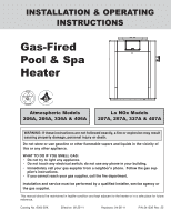
INSTALLATION & OPERATING
INSTRUCTIONS
Gas-Fired
Pool & Spa
Heater
Catalog No. 6000.59X
Effective: 08-25-11
Replaces: 04-26-11
P/N 241236 Rev. 25
WARNING: If these instructions are not followed exactly, a fire or explosion may result
causing property damage, personal injury or death.
WHAT TO DO IF YOU SMELL GAS:
• Do not try to light any appliance.
• Do not touch any electrical switch; do not use any phone in your building.
• Immediately call your gas supplier from a neighbor's phone. Follow the gas sup-
plier's instructions.
• If you cannot reach your gas supplier, call the fire department.
Installation and service must be performed by a qualified installer, service agency or
the gas supplier.
This manual should be maintained in legible condition and kept adjacent to the heater or in a safe place for future
reference.
Atmospheric Models
206A, 266A, 336A & 406A
Lo NOx Models
207A, 267A, 337A & 407A
Do not store or use gasoline or other flammable vapors and liquids in the vicinity of
this or any other appliance.