Ridgid R4510 Operation Manual
Ridgid R4510 Manual
 |
View all Ridgid R4510 manuals
Add to My Manuals
Save this manual to your list of manuals |
Ridgid R4510 manual content summary:
- Ridgid R4510 | Operation Manual - Page 1
OPERATOR'S MANUAL 10 in. TABLE SAW R4510 / R45101 Your table saw has been engineered and manufactured to our high standards for dependability, ease of operation, and operator safety. When properly cared for, it will give you years of rugged, trouble-free performance. WARNING: To reduce the risk of - Ridgid R4510 | Operation Manual - Page 2
of Terms...8 Features...9-11 Tools Needed...13 Loose Parts...14-22 Assembly...15-23 Operation...23-37 Adjustments...38-42 Maintenance...43-44 Accessories...44 Troubleshooting...45-46 Warranty...47 Parts Ordering/Service...Back Page INTRODUCTION This tool has many features for - Ridgid R4510 | Operation Manual - Page 3
in use, before servicing, or when changing attachments, blades, bits, cutters, etc., all tools should be disconnected. AVOID ACCIDENTAL STARTING. Be sure switch is off when plugging in any tool. USE RECOMMENDED ACCESSORIES. Consult the operator's manual for recommended accessories. The use of - Ridgid R4510 | Operation Manual - Page 4
all "through-sawing" operations. Through-sawing operations are those in which the blade cuts completely through the workpiece as in ripping or cross cutting. Keep the blade guard down, the anti-kickback pawls down, and the riving knife in place. ALWAYS SECURE WORK firmly against the rip fence or - Ridgid R4510 | Operation Manual - Page 5
the rear and sides of the saw table for wide or long workpieces. AVOID KICKBACKS (work thrown back toward you) by: a) Keeping blade sharp. b) Keeping rip fence parallel to the saw blade. c) Keeping riving knife, anti-kickback pawls, and blade guard in place and operating. d) Not releasing the work - Ridgid R4510 | Operation Manual - Page 6
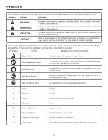
reduce the risk of injury, user must read and understand operator's manual before using this product. Eye Protection No Hands Symbol Always wear eye protection with side shields marked to comply with ANSI Z87.1. Failure to keep your hands away from the blade will result in serious personal injury - Ridgid R4510 | Operation Manual - Page 7
with or without yellow stripes is the grounding wire. Check with a qualified electrician or service personnel if the grounding instructions are not completely understood, or if in doubt as to whether the tool is properly grounded. Repair or replace a damaged or worn cord immediately. This product is - Ridgid R4510 | Operation Manual - Page 8
Per Minute (RPM) The number of turns completed by a spinning object in one minute. Ripping or Rip Cut A cutting operation along the length of the workpiece. Riving Knife (table saws) A metal piece, slightly thinner than the blade, which helps keep the kerf open and also helps to prevent kickback - Ridgid R4510 | Operation Manual - Page 9
r/min. (RPM) RIVING KNIFE ANTI-KICKBACK PAWLS BLADE GUARD ASSEMBLY SAW BLADE MITER GAUGE RIP FENCE MICRO-ADJUST WHEEL LOCKING LEVER FRONT RAIL BLADE WRENCHES BEVEL SCALE GRIPS BLADE AND BLADE WRENCH STORAGE LEG STAND BEVEL LOCKING LEVER SWITCH ASSEMBLY BEVEL ADJUSTING HANDWHEEL BEVEL - Ridgid R4510 | Operation Manual - Page 10
rip fence. RIP FENCE - A sturdy metal fence guides the workpiece and is secured with the locking lever. Grooves run along the top and sides of the rip fence for use with optional clamps and accessories. RIVING KNIFE - A removable metal piece of the blade guard assembly, slightly thinner than the saw - Ridgid R4510 | Operation Manual - Page 11
and is surrounded by an insert called the throat plate. The height of the blade is set with a handwheel on the front of the cabinet. To accommodate wide panels, the saw table has rails on each side. Detailed instructions are provided in the Operation section of this manual for the basic cuts: cross - Ridgid R4510 | Operation Manual - Page 12
for assembly and adjustments: FRAMING SQUARE PHILLIPS SCREWDRIVER FLATHEAD SCREWDRIVER COMBINATION SQUARE C-CLAMPS LOOSE PARTS LIST The following items are included with your table saw: ANTI-KICKBACK PAWLS RIP FENCE Fig. 5 SWITCH KEY BLADE GUARD MITER GAUGE PUSH STICK BLADE WRENCHES (2) 12 - Ridgid R4510 | Operation Manual - Page 13
LOOSE PARTS LIST SCREW UPPER TUBE HANDLE SECTION CENTER BRACE CARRIAGE BOLT OUTER TUBE LOCK NUT LARGE SPACER SMALL SPACER FLAT WASHER, SMALL WHEEL LOCK NUT FLAT WASHER, LARGE INNER LEG ASSEMBLY Fig. 7 13 - Ridgid R4510 | Operation Manual - Page 14
you have carefully inspected and satisfactorily operated the tool. The saw is factory set for accurate cutting. After assembling it, check for accuracy. If shipping has influenced the settings, refer to specific procedures explained in this manual. If any parts are damaged or missing, please - Ridgid R4510 | Operation Manual - Page 15
assembly (curve side up) with the stop pin under the pedal assembly latch. NOTE: The stop pins rest on top of inner leg assembly. Insert a carriage bolt through the top hole of the inner leg assembly lock, do not use; contact an authorized service center for assistance. UPPER TUBE SMALL SPACER - Ridgid R4510 | Operation Manual - Page 16
on the leg stand. Align the holes in the table with the holes in the end braces. Insert a bolt through the hole in the table saw and into the hole in the stand. Add a lock washer, flat washer, ring terminal (from switch box), and a hex nut. Hand tighten. See Figure 9. For the three remaining - Ridgid R4510 | Operation Manual - Page 17
ASSEMBLY TO OPEN THE LEG STAND See Figures 10 - 12 Grasp the grips on the saw table and stand it upright as shown below. With your hands on the grips, push the leg stand towards the ground until the table saw is in an open position. NOTE: The release lever will close over the center brace - Ridgid R4510 | Operation Manual - Page 18
saw's accessories. These accessories must be securely stored prior to closing the leg stand and moving the saw. WING NUT PUSH STICK LEVELING FOOT BLADE BLADE WRENCHES WING NUT MITER GAUGE Fig. 13 ANTI-KICKBACK PAWLS ANTI-KICKBACK PAWLS / BLADE GUARD STORAGE BLADE GUARD Fig. 14 18 RIP FENCE - Ridgid R4510 | Operation Manual - Page 19
ASSEMBLY TO CLOSE THE LEG STAND AND MOVE THE SAW See Figures 16 - 19. Remove any workpieces from the tool. Remove and securely store any tools or accessories such as rip fence, miter gauge, clamps, blade guard, etc. Lower the saw blade. To close the leg stand: At the same time, step on the - Ridgid R4510 | Operation Manual - Page 20
for all other cutting operations. Unplug the saw. To place in the "up" position for all through cutting: Remove the throat plate. Raise the saw blade by turning the height adjusting knob clockwise. Unlock the release lever by pulling it up. Grasp the riving knife and pull it towards - Ridgid R4510 | Operation Manual - Page 21
. Anti-kickback pawls should only be installed for through cuts. Unplug the saw. Fig. 23 Raise the saw blade by turning the height/bevel adjusting handwheel clockwise. Place riving knife in "up" position. Reinstall the throat plate. Align the slot in the pawls over the rear hole in the - Ridgid R4510 | Operation Manual - Page 22
RIVING KNIFE AND SAW BLADE See Figure 25. If the riving knife is out of alignment with the saw blade, adjustment is needed. To check alignment of the riving knife: Unplug the saw. Raise the saw blade by turning the height adjusting knob clockwise. Remove the anti-kickback pawls and blade guard - Ridgid R4510 | Operation Manual - Page 23
the workpiece securely against the saw table or fence. Clean the saw, blade guard, under the throat plate, and any areas where saw dust or scrap workpieces may gather. Use the right type of blade for the cut being made. Always use the riving knife for every operation where it is allowed. The - Ridgid R4510 | Operation Manual - Page 24
and resting firmly on the saw table. From the back side of the rip fence, secure the wood to the fence using 1-3/4 in. wood screws. HOW TO MAKE A JIG (FOR RIP CUTTING NARROW WORKPIECE) See Figure 28. If ripping a narrow workpiece places the hands too close to the blade, it will be necessary to - Ridgid R4510 | Operation Manual - Page 25
a compound miter cut. 6 BEVEL RIP CUT CUTTING TIPS Dado and rabbet cuts are non-through cuts which can be either rip cuts or cross cuts. Carefully read and understand all sections of this operator's manual before attempting any operation. WARNING: Do not use blades rated less than the speed of - Ridgid R4510 | Operation Manual - Page 26
to be performed and lock the rip fence. Place the workpiece against the fence and over the saw blade area. Adjust the featherboard to apply resistance to the workpiece just forward of the blade. Attach C-clamps to secure the featherboard to the edge of the saw table. WARNING: Place the featherboard - Ridgid R4510 | Operation Manual - Page 27
firmly against the miter gauge. Turn off the table saw. Once the blade has stopped, pull the miter gauge back until the freshly cut wood is over the disc. GULLET TO LOCK BEVEL LOCKING LEVER Fig. 32 TO UNLOCK HEIGHT ADJUSTING KNOB BLADE HEIGHT LOCK KNOB TO INCREASE ANGLE BEVEL LOCKING LEVER - Ridgid R4510 | Operation Manual - Page 28
scale on the front rail. NOTE: The anti-kickback pawls and blade guard assembly must be removed to perform this adjustment. Reinstall the blade guard assembly when the adjustment is complete. Unplug the saw. Place the rip fence on the saw table so that it lightly touches the right side of the - Ridgid R4510 | Operation Manual - Page 29
the length of the saw table by using the sliding table extension. Remove the rip fence. Unlock the sliding table extension by lifting the table extension lock lever. Slide the table extension to the desired width. NOTE: Use the scale on the front rail when a specific width is desired. Once - Ridgid R4510 | Operation Manual - Page 30
amount. WARNING: To reduce the risk of injury from kickback, align the rip fence to the blade following any blade adjustments. Always make sure the rip fence is parallel to the blade before beginning any operation. 30 MITER GAUGE GROOVE COMBINATION SQUARE Fig. 41 MITER GAUGE COMBINATION GROOVE - Ridgid R4510 | Operation Manual - Page 31
Fig. 44 WARNING: Make sure the blade guard assembly is installed and working properly to avoid serious personal injury. SWITCH ON SWITCH OFF Remove the rip fence by lifting the locking lever. Set the blade to the correct depth for the workpiece. Set the miter gauge to 0° and tighten - Ridgid R4510 | Operation Manual - Page 32
ANGLED WARNING: Make sure the blade guard assembly is installed and working properly to avoid serious personal injury. BEVEL ADJUSTING HANDWHEEL Fig. 47 Set the blade to the correct depth for the workpiece. Remove the rip fence by lifting the locking lever. Set the miter gauge to desired - Ridgid R4510 | Operation Manual - Page 33
rip fence by lifting the locking lever. Unlock the bevel locking lever. Turn the bevel adjusting handwheel until the bevel indica- tor is at the desired angle. Push the bevel locking lever securely to the left to lock the angle. Push the bevel locking lever toward the table to relock. Set - Ridgid R4510 | Operation Manual - Page 34
BEVEL RIP CUT RIP FENCE WARNING: Make sure the blade guard assembly is installed and working properly to avoid serious personal injury. Remove the miter gauge. Unlock the bevel locking lever. Adjust the bevel angle to the desired setting. Lock the bevel locking lever. Set the blade to - Ridgid R4510 | Operation Manual - Page 35
panel. WARNING: Make sure the blade guard assembly is installed and working properly to avoid serious personal injury. BEVEL ADJUSTING HANDWHEEL Fig. 52 Place a support the same height as the top of the saw table behind the saw for the cut work. Add supports to the sides as needed. Depending - Ridgid R4510 | Operation Manual - Page 36
cut such as rabbets or dadoes. To avoid personal injury, always use push blocks, push sticks, and featherboards. Unplug the saw. Remove the blade guard and anti-kickback pawls. Place riving knife in "down" position. Unlock the bevel locking lever. Adjust the bevel angle to 0°. Turn - Ridgid R4510 | Operation Manual - Page 37
OPERATION MAKING A DADO CUT See Figure 54. An optional dado throat plate is required for this procedure (refer to the Accessories section later in this manual and check with the retailer where the table saw was purchased). All blades and dado sets must not be rated less than the speed of this tool. - Ridgid R4510 | Operation Manual - Page 38
to be sure adjustments are needed. TO REPLACE THE BLADE See Figures 55 - 56. Blade kerf width must be within the limits stamped on the riving knife. Unplug the saw. Lower the saw blade and remove the throat plate. Raise the saw blade to full height then remove the blade guard and anti-kickback - Ridgid R4510 | Operation Manual - Page 39
it is even with the top of the saw table using a hex key. Release the bevel locking lever and position the bevel adjusting handwheel until blade is 0º to the table. Lock the bevel locking lever. Screw the 0º stop screw until the saw blade starts to move. Check again for squareness and readjust - Ridgid R4510 | Operation Manual - Page 40
saw table using a hex key. Release the bevel locking lever and position the bevel adjusting handwheel until blade is 45º to the table. Lock the bevel locking lever. Screw the 45º stop screw until the saw blade starts . If adjustment is required: Loosen the lock knob. Loosen set screw. - Ridgid R4510 | Operation Manual - Page 41
TO CHECK AND ADJUST THE ALIGNMENT OF THE RIP FENCE See Figures 63 - 65. The rip fence must be parallel to the saw blade and the miter gauge grooves. WARNING: A misaligned rip fence can cause kickbacks and jams. To reduce the risk of injury, always maintain proper rip fence alignment Unplug the - Ridgid R4510 | Operation Manual - Page 42
nut against coupling. TO ADJUST THE TABLE EXTENSION See Figure 68. Lock table extension lever. Loosen the four nuts underneath the sliding table extension. Use a combination square to make sure the top of the sliding table extension is the same height as the main table. Tighten the four hex - Ridgid R4510 | Operation Manual - Page 43
(including those on the blade guard assembly and miter gauge). NYLON SET SCREW AND NUT Fig. 69 NYLON SET SCREW ADJUSTMENT See Figure 69. If the saw blade has a slight amount of lateral movement, the nylon set screw needs to be tightened. Unplug the saw. Lower blade completely and bevel to 45 - Ridgid R4510 | Operation Manual - Page 44
Do not overtighten. BRUSH CAP BRUSH ASSEMBLY Fig. 70 ACCESSORIES Look for these accessories where you purchased this product: AC31DP1 AC9933 Dado Throat Plate Flip Top Portable Work Support WARNING: Current attachments and accessories available for use with this tool are listed above. Do not - Ridgid R4510 | Operation Manual - Page 45
Slow the feed rate. Align the rip fence. See To Check and Align the Blade Guard Assembly in the Assembly section. Replace the wood. Always cut with convex side to table surface. Rip fence is misaligned. Blade not properly aligned or set. Check and adjust the rip fence. Resharpen or set blade. 45 - Ridgid R4510 | Operation Manual - Page 46
. Saw does not start. Power cord not plugged in. Plug in power cord. Circuit fuse is blown. Replace circuit fuse. Circuit breaker is tripped. Reset circuit breaker. Cord, switch, or motor is damaged. Have replaced by qualified service center. Blade makes poor cuts. Motor overheats. Motor - Ridgid R4510 | Operation Manual - Page 47
or by logging on to the RIDGID® website at www.ridgid.com. When requesting warranty service, you must present the original dated sales receipt. The authorized service center will repair any faulty workmanship, and either repair or replace any part covered under the warranty, at our option, at no - Ridgid R4510 | Operation Manual - Page 48
OPERATOR'S MANUAL 10 in. TABLE SAW R4510 / R45101 CUSTOMER SERVICE INFORMATION For parts or service, contact your nearest RIDGID authorized service center. Be sure to provide all relevant information when you call or visit. For the location of the authorized service center nearest you, please call
-
 1
1 -
 2
2 -
 3
3 -
 4
4 -
 5
5 -
 6
6 -
 7
7 -
8
-
9
-
10
-
11
-
12
-
13
-
14
-
15
-
16
-
17
-
18
-
19
-
20
-
21
-
22
-
23
-
24
-
25
-
26
-
27
-
28
-
29
-
30
-
31
-
32
-
33
-
34
-
35
-
36
-
37
-
38
-
39
-
40
-
41
-
42
-
43
-
44
-
45
-
46
-
47
-
48
 |
 |

Your table saw has been engineered and manufactured to our high standards for dependability, ease of operation, and
operator safety. When properly cared for, it will give you years of rugged, trouble-free performance.
WARNING:
To reduce the risk of injury, the user must read and understand the operator’s manual before using this
product.
Thank you for buying a RIDGID
®
product.
OPERATOR’S MANUAL
10 in. TABLE SAW
R4510 / R45101
SAVE THIS MANUAL FOR FUTURE REFERENCE