Ryobi 6090080-1 English Manual
Ryobi 6090080-1 Manual
 |
View all Ryobi 6090080-1 manuals
Add to My Manuals
Save this manual to your list of manuals |
Ryobi 6090080-1 manual content summary:
- Ryobi 6090080-1 | English Manual - Page 1
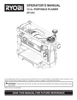
OPERATOR'S MANUAL 13 in. PORTABLE PLANER AP1301 Your portable planer has been engineered and manufactured to our high standard for dependability, ease of operation, and operator safety. When properly cared for, it will give you years of rugged, trouble-free performance. WARNING: To reduce the risk - Ryobi 6090080-1 | English Manual - Page 2
Symbols...6-7 Electrical ...8 � Glossary of Terms...9 � Features...10-11 Loose Parts ...11 � Assembly ...12-13 � Operation...14-16 Adjustments...17 � Maintenance ...18-19 Troubleshooting ...20 � Parts Ordering / Service ...22 INTRODUCTION This tool has many features for making its use - Ryobi 6090080-1 | English Manual - Page 3
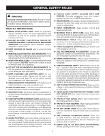
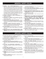
and safer performance. Follow instructions for lubricating and changing accessories. DISCONNECT TOOLS. When not in use, before servicing, or when changing attachments, blades, bits, cutters, etc., all tools should be disconnected. AVOID ACCIDENTAL STARTING. Be sure switch is off when plugging - Ryobi 6090080-1 | English Manual - Page 4
. WHEN SERVICING use only identical replacement parts. Use of any other parts may create a hazard or cause product damage. USE ONLY RECOMMENDED ACCESSORIES listed in this manual or addendums. Use of accessories that are not listed may cause the risk of personal injury. Instructions for safe use - Ryobi 6090080-1 | English Manual - Page 5
THE CUTTER HEAD to reach full speed before using the planer. REPLACEMENT PARTS. All repairs, whether electrical or mechanical, should be made at your nearest authorized service center. DO NOT attempt to turn cutter head with hands. IF ANY PART OF THIS TOOL IS MISSING or should break, bend, or - Ryobi 6090080-1 | English Manual - Page 6
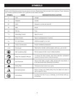
shields, or a full face shield when operating this product. Precautions that involve your safety. No Hands Symbol Failure to keep your hands away from the blade will result in serious personal injury. Hot Surface To reduce the risk of injury or damage, avoid contact with any hot - Ryobi 6090080-1 | English Manual - Page 7
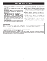
CENTER for repair. When servicing, use only identical replacement parts. WARNING: To avoid serious personal injury, do not attempt to use this product until you read thoroughly and understand completely the operator's manual. If you do not understand the warnings and instructions in the operator - Ryobi 6090080-1 | English Manual - Page 8
distance. A line that can support one power tool may not be able to support two or three tools. GROUNDING INSTRUCTIONS In the event of a service personnel if the grounding instructions are not completely understood, or if in doubt as to whether the tool is properly grounded. Repair or replace - Ryobi 6090080-1 | English Manual - Page 9
set) outward from the face of the blade. Snipe (planers) Depression made at either end of a workpiece by cutter blades when the workpiece is not properly supported. Through Sawing Any cutting operation where the blade extends completely through the thickness of the workpiece. Throw-Back The throwing - Ryobi 6090080-1 | English Manual - Page 10
26 FPM No Load Speed 10,000 r/min. (RPM) Motor 2 HP Peak Input 120 V, AC Only, 60Hz, 15 A Max Planing Height 6 in. Max. Planing Width 13 in. Max. Planing Depth 1/8 in. Net Weight 53.5 lbs. DEPTH ADJUSTMENT HANDLE SWITCH KEY POWER SWITCH DUST PORT WORK TABLE 10 THICKNESS SCALE Fig. 2 - Ryobi 6090080-1 | English Manual - Page 11
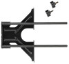
switch with a removable switch key. THICKNESS SCALE The thickness scale accurately displays the height of the cutter blades to a maximum of 6 in. WORK TABLE The work table supports your workpiece. LOOSE PARTS 3 2 6 5 1 4 Key No. 1 2 3 4 5 6 Fig. 3 Description Qty. Depth Adjustment Handle - Ryobi 6090080-1 | English Manual - Page 12
the tool and any accessories from the box. Place it on a level work surface. NOTE: This tool is heavy. To avoid back injury, lift with your 2579 for assistance. WARNING: If any parts are damaged or missing do not operate this tool until the parts are replaced. Failure to heed this warning could - Ryobi 6090080-1 | English Manual - Page 13
walking is noted, secure workbench or support surface before beginning planing operation. INSTALLING DEPTH ADJUSTMENT HANDLE See Figure 5. Locate the hex key, depth adjustment handle, and hex head screw among the loose parts. Place the depth adjustment handle onto the depth gauge shaft. Insert - Ryobi 6090080-1 | English Manual - Page 14
the planer apply the proper feed rate. APPLICATIONS You may use this tool for the purpose listed below: Planing the surface of solid wood and wood products THICKNESS PLANING Thickness planing sizes the workpiece to a desired thickness while creating a smooth, level surface. The thickness of each - Ryobi 6090080-1 | English Manual - Page 15
cutter blades to chip the workpiece. POWER SWITCH See Figure 6. The planer is equipped with a power switch that has a built-in locking feature. This feature is intended to prevent unauthorized and possible hazardous use by children and others. TO TURN THE PLANER ON: With the switch key inserted - Ryobi 6090080-1 | English Manual - Page 16
Adjustments section for further instructions. Before each use of the planer, check for loose fasteners, fittings, or hardware; be sure the dust hood is securely mounted; and ensure the blade cutter rotates freely. Lower the cutter head assembly to approximately 1 in. above the planer table surface - Ryobi 6090080-1 | English Manual - Page 17
or other particles on a workpiece and then running the workpiece through the planer. Slight adjustments can be made to one or both blades to offset such planing imperfections. Unplug the planer and remove the switch key. Lower the cutter head assembly. Remove the two thumb screws holding the - Ryobi 6090080-1 | English Manual - Page 18
planer is equipped with two double-edged blades (replacement part number AC8630) attached to a rotating cutter head. Worn blades will affect cutting accuracy and may produce ridges on the workpiece. TO REPLACE: Unplug the planer and remove the switch key parts (spindle, roller surfaces, handles, - Ryobi 6090080-1 | English Manual - Page 19
10 to 15 operating hours for wear. Replace both brushes when either brush has less than 1/4 in. of carbon remaining. NOTE: The dust hood may be removed for easier access when removing the rear brush cap. Unplug planer and remove the switch key. Using a flat-head screwdriver, unscrew the brush - Ryobi 6090080-1 | English Manual - Page 20
TROUBLESHOOTING Problem Possible Cause Solution Snipe (depressions at ends of Dull cutter blades workpiece) Incorrect butted stock Unit not securely mounted Replace or turn cutter blades. Butt pieces end-to-end as they are fed into planer. Tighten lag bolts. Torn grain Too deep a blade - Ryobi 6090080-1 | English Manual - Page 21
NOTES 21 - Ryobi 6090080-1 | English Manual - Page 22
OPERATOR'S MANUAL 13 in. PORTABLE PLANER AP1301 • SERVICE Now that you have purchased your tool, should a need ever exist for repair parts or service, simply contact your nearest Authorized Service Center. Be sure to provide all pertinent facts when you call or visit. Please call 1-800-525-2579 for
-
 1
1 -
 2
2 -
 3
3 -
 4
4 -
 5
5 -
 6
6 -
 7
7 -
8
-
9
-
10
-
11
-
12
-
13
-
14
-
15
-
16
-
17
-
18
-
19
-
20
-
21
-
22
 |
 |

Your portable planer has been engineered and manufactured to our high standard for dependability, ease of operation, and
operator safety. When properly cared for, it will give you years of rugged, trouble-free performance.
WARNING:
To reduce the risk of injury, the user must read and understand the operator’s manual before using
this product.
Thank you for your purchase.
SAVE THIS MANUAL FOR FUTURE REFERENCE
OPERATOR’S MANUAL
13 in. PORTABLE PLANER
AP1301