Ryobi A99DLK4 Operation Manual
Ryobi A99DLK4 Manual
 |
View all Ryobi A99DLK4 manuals
Add to My Manuals
Save this manual to your list of manuals |
Ryobi A99DLK4 manual content summary:
- Ryobi A99DLK4 | Operation Manual - Page 1
flathead bit. Tighten securely. Follow drill manual instructions to install hole saw assembly into chuck. door so the hole saw enters the hole guide and door evenly. With 2-1/8 inch hole the RYOBI Door Latch Installation Kit (Model# A99LM2) Fig. 1 B C H A D F G E A - Bracket (support, - Ryobi A99DLK4 | Operation Manual - Page 2
support de la porte. Conserver les vis pour pouvoir installer la plaque du loquet. Suivre les instructions RYOBI (Modèle n° A99LM2) ESPAÑOL JUEGO DE INSTALACIÓN PARA TRABAS DE PUERTAS DE METAL Y MADERA A99DLK4 firmemente. Siga las instrucciones del manual del taladro para instalar la sierra
-
 1
1 -
 2
2
 |
 |

2-3/4"
2-3/8"
WOOD AND METAL DOOR
LOCK INSTALLATION KIT
A99DLK4
WARNING:
To reduce the risk of injury, do not attempt to use this
product until you have read thoroughly and understand
completely this operator’s manual and the operator’s
manual for any power tools used.
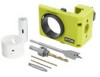
PACKING LIST
See Figure 1.
Bracket
1 in. Spade Bit
1 in. Bi-metal Hole Saw
2-1/8 in. Bi-metal Hole Saw
Arbor with Adjustable Pilot Bit
1/8 in. Drill Bit
3/32 in. Drill Bit
PH2/8-10SL Double Ended Bit
TOOLS NEEDED
AC Power Drill or DC Drill 18 Volts or more
APPLICATIONS
You may use this tool for the following purpose:
Installing lock sets and dead bolts easily and accurately
without measuring.
INSTRUCTIONS
See Figures 2 - 7.
Read hardware instructions to find backset location.
Select desired backset by depressing backset adjustment
tabs and sliding cross bore left for 2-3/4 in. or right for 2-3/8
in. backset. Check that cross bore is securely locked in
place.
Spread bracket to fit
1-3/4 in. door. Do not spread bracket
for 1-3/8 in. doors.
Position bracket on door using the auto-strike locator. Line
up locator with the center of the strike plate in the door jamb
by shutting the door and positioning the bracket until it falls
into the strike plate.
Secure the bracket to the door using the latch plate screws
(included with the door lock hardware) into the bracket.
Using a screwdriver or drill, secure bracket firmly to the
door. Check that bracket does not move.
Adjust length of pilot bit to fit 2-1/8 in. hole saw depth by
loosening the arbor screw using the supplied flathead bit.
Tighten securely.
Follow drill manual instructions to install hole saw assembly
into chuck.
NOTE:
For a straight hole, be sure drill is at a right angle
to the door so the hole saw enters the hole guide and door
evenly.
With 2-1/8 inch hole saw, drill from one side until pilot bit
shows on opposite side of the door. Drill on the opposite
side, lining up pilot bit with pilot bit hole. Meet the two holes
in the center of door and drill through.
Before drilling 1 in. latch bore hole, adjust the pilot bit length
to the 1 in. hole saw depth and tighten securely. Using the
1 in. hole saw, drill latch bore. Keep drill at a right angle to
door flat to ensure straight hole.
NOTE:
Some hardware requires latch bore to extend be-
yond cross bore hole. In this case, use 1 in. spade bit to
drill beyond cross bore hole.
Remove screws and bracket from the door. Save screws to
install latchplate.
Follow directions included with door hardware for further
instructions on installing. Use included tools to install
hardware.
If installing a lock set with a rectangular, flush-mounted
strike plate, use the RYOBI Door Latch Installation Kit
(Model# A99LM2)
Fig. 1
A - Bracket (support, suporte)
B - 2-1/8 in. cross bore (trou transversal de 54 mm (2 1/8 po), orificio
transversal de 54 mm (2-1/8 pulg.)
C - Latch bore (trou de loquet, orificio del pestillo)
D - Auto-strike locator (localisateur à martelage automatique, indicador de
posición con golpe automático)
E - 2-3/4 in. backset
[fente pour martelage automatique de 69,85 mm
(2-3/4 po), ranura de golpe automático de 69,85 mm (2-3/4 in)]
F - 2-3/8 in. backset [fente pour martelage automatique de 60,33 mm
(2-3/8 po), ranura de golpe automático de 60,33 mm (2-3/8 in)]
G - Backset adjustment tabs (languettes d’ajustement de distance de retrait,
pestañas de ajuste del conjunto trasero )
C
A
Fig. 2
Fig. 4
B
A - Bracket (support, suporte)
B - 1 in. bi-metal hole saw [scie cloche bimétal de 25,4 mm (1 po), sierra de
perforación bimetal de 25,4 mm (1 pulg.)]
C - 2-1/8 in. bi-metal hole saw [scie cloche bimétal de 53,98 mm (2-1/8 po),
sierra de perforación bimetal de 53,98 mm (2-1/8 pulg.)]
D - 1 in. spade bit (foret à trois, pointes de 25,4 mm (1 po) broca de pala
de 25,4 mm (1 pulg.)
E - Arbor with adjustable pilot bit (arbre avec mèche pilote ajustable, mandril
con broca pilato ajustable)
F - 1/8 in. drill bit [foret de 3,18 mm (1/8 po), punta de destornillador de
3,18 mm (1/8 pulg.)]
G - 3/32 in. drill bit [foret de 2,4 mm (3/32 po), punta de destornillador de
2,4 mm (3/32 pulg.)]
H - PH2/8-10SL Double ended bit (embout double 8-10SL nº 2, broca de
doble extremo 8-10SL N.º 2)
Fig. 5
Fig. 6
A
H
G
F
C
D
B
E
A - Arbor with adjustable pilot bit (arbre avec mèche pilote ajustable, mandril
con broca pilato ajustable)
B - Arbor screw (vis de l’arbre, tornillo del árbol)
C - Hole saw (a scie-cloche, la sierra de perforación)
D - Hole saw assembly (assemblage de la scie-cloche, conjunto de la sierra
de perforación)
A
C
DRILL CROSS BORE
PERCER LE TROU TRANSVERSAL
PERFORAR ORIFICIO TRANSVERSAL
DRILL LATCH BORE
PERCER LE TROU DU LOQUET
PERFORAR ORIFICIO DEL PESTILLO
A - Door (arrière, puertas)
B - Bracket (support, suporte)
C - Auto-strike locator (localisateur à martelage automatique, indicador de
posición con golpe automático)
D - Latch plate screws (vis de plaque du loquet , lornillos de la placa del
pestillo)
Fig. 7
B
C
D
B
A - Backset (appui, distancia al centro del picaporte)
Fig. 2
A
G
G
F
E
D
D
A