Ryobi ACTIL01 Operation Manual
Ryobi ACTIL01 Manual
 |
View all Ryobi ACTIL01 manuals
Add to My Manuals
Save this manual to your list of manuals |
Ryobi ACTIL01 manual content summary:
- Ryobi ACTIL01 | Operation Manual - Page 1
manual for their cultivator before using this accessory. Save these instructions. Refer to them frequently and use them to instruct described in these instructions, take your unit to a qualified service center. WARNING: problem with the cultivating operation of the unit, check for proper tine - Ryobi ACTIL01 | Operation Manual - Page 2
prêté, il doit être accompagné de ces instructions. AVERTISSEMENT : S'assurer que l'accessoire est compatible veuillez apporter votre unité à un centre de service qualifié. Español ACTIL01 DIENTES BOLO DE RECAMBIO el usuario debe leer y comprender el manual del operador de la cultivadora antes de
-
 1
1 -
 2
2
 |
 |

WARNING:
To reduce the risk of injury, user must read and understand the operator’s
manual for their cultivator before using this accessory. Save these instruc-
tions. Refer to them frequently and use them to instruct other users. If you
loan someone this product, loan them these instructions also.
WARNING:
Ensure compatibility and fit before using this accessory. Do not use this
accessory if a part is damaged or missing. If you are not comfortable per-
forming any of the functions described in these instructions, take your unit
to a qualified service center.
WARNING:
Always protect hands by wearing heavy gloves and/or wrapping the cutting
edges of the tines with rags and other material when installing or removing
tines. Contact with the tines could result in serious personal injury.
REMOVING AND REPLACING THE TINES
See Figure 1.
Remove the battery pack.
Remove the hitch pin and tines from one side of the tine shaft.
Remove vines, grass or other obstructions wrapped around the tine shaft.
Dispose of the old tines.
Install the new tines with the tips angled in the same direction as the tines
you removed and secure with hitch pin.
Repeat these steps to install the other side of the tine shaft.
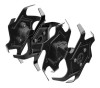
NOTE:
The tool has four tines for cultivating — two inner tines stamped “B”
and “C”, and two outer tines stamped “A” and “D”. When viewed from the
front, as shown, the tines stamped “D”
and “C” are on the left and the tines
stamped “A” and “B” are on the right. For correct operation of the unit, the
tines must be installed in the correct orientation.
NOTE:
The unit will not operate properly if the tines are installed incorrectly.
If you notice a problem with the cultivating operation of the unit, check for
proper tine positioning.
Fig. 1
A - Outer tine “A” (right) [lame extérieure « A » (droite),
aspa exterior “A” (derecha)]
B - Inner tine “B” (right) [lame intérieure « B » (droite),
aspa interior “B” (derecha)]
C - Inner tine “C” (left) [lame intérieure« C » (gauche), aspa interior “C” (izquierdo)]
D - Outer tine “D” (left) [lame extérieure « D »
(gauche), aspa exterior “D” (izquierdo)]
E - Hitch pin (goupille de sûreté, pasador del enganche)
E
E
A
B
C
D
VIEW FROM THE FRONT
(VUE DE FACE, VISTA DESDE EL FRENTE)
FOR USE WITH P2705 RYOBI 18 VOLT CULTIVATOR
ACTIL01
REPLACEMENT BOLO TINES