Ryobi ACTIL03 Operation Manual
Ryobi ACTIL03 Manual
 |
View all Ryobi ACTIL03 manuals
Add to My Manuals
Save this manual to your list of manuals |
Ryobi ACTIL03 manual content summary:
- Ryobi ACTIL03 | Operation Manual - Page 1
operator's manual for their cultivator before using this accessory. Save these instructions. Refer to them frequently and use them to instruct other performing any of the functions described in these instructions, take your unit to a qualified service center. WARNING: Always protect hands by wearing - Ryobi ACTIL03 | Operation Manual - Page 2
êté, il doit être accompagné de ces instructions. Español ACTIL03 DIENTES DE REPUESTO PARA el usuario debe leer y comprender el manual del operador de la cultivadora antes de directives, veuillez apporter votre unité à un centre de service qualifié. ADVERTENCIA: Antes de usar el accesorio, aseg
-
 1
1 -
 2
2
 |
 |

WARNING:
To reduce the risk of injury, user must read and understand the operator’s
manual for their cultivator before using this accessory. Save these instruc-
tions. Refer to them frequently and use them to instruct other users. If you
loan someone this product, loan them these instructions also.
WARNING:
Ensure compatibility and fit before using this accessory. Do not use this
accessory if a part is damaged or missing. If you are not comfortable per-
forming any of the functions described in these instructions, take your unit
to a qualified service center.
WARNING:
Always protect hands by wearing heavy gloves and/or wrapping the cutting
edges of the tines with rags and other material when installing or removing
tines. Contact with the tines could result in serious personal injury.
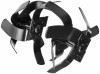
REMOVING AND REPLACING THE TINES
See Figure 1.
With user facing the REAR of the tiller, the left tine assembly is marked “L”. The
right inner tine assembly is marked “R”.
For correct operation of the unit, the
tines must be installed in the correct position.
From the rear of the tool, tilt the unit forward and lift the dirt flap up to access
the tine shaft.
NOTE:
If the side panels are installed, remove them.
Place the tine assemblies on the tine shaft as shown.
Rotate the tine assemblies until the holes in the assemblies are aligned with
the holes in the tine shaft.
NOTE:
If the holes do not align, the tine assemblies may be installed on the
wrong sides. Reverse the position of the tine assemblies and check for hole
alignment.
Insert shear pins through the holes in the tine assemblies and the shaft.
Secure with hitch clips.
Fig. 1
FOR USE WITH RY40702 RYOBI 40 VOLT REAR TINE TILLER
ACTIL03
REPLACEMENT TINES
A
B
C
D
E
A - Left tine assembly (assemblage de dent gauche, conjunto de púas izquierdo)
B - Tine shaft (arbre de dents, eje de las púas)
C - Shear pin (goupille de verrouillage, pasador de fijación)
D- Hitch clip (pince d’attelage, gancho)
E - Right tine assembly (assemblage de dent droite, conjunto de púas derecho)
VIEW FROM THE REAR
(VUE DE L’ARRIÈRE, VISTA DEL LADO TRASERO)